ISSN 1392–124X (print), ISSN 2335–884X (online) INFORMATION TECHNOLOGY AND CONTROL, 2014, T. 43, Nr. 2
Non-Identical Synchronization, Anti-Synchronization and Control of
Single-Machine Infinite-Bus Power System via Active Control
Uğur Erkin Kocamaz
1*, Yılmaz Uyaroğlu
21 Department of Computer Technologies, Vocational School of Karacabey, Uludağ University, 16700 Karacabey, Bursa, Turkey
e-mail: [email protected]
2 Department of Electrical & Electronics Engineering, Faculty of Engineering, Sakarya University, 54187 Serdivan, Sakarya, Turkey
e-mail: [email protected]
http://dx.doi.org/10.5755/j01.itc.43.2.4677
Abstract. Since the idea of synchronizing two identical chaotic systems under different initial conditions was first introduced by Pecora and Carroll, the synchronization of chaotic systems has attracted much attention, and the synchronization of non-identical chaotic systems has also been investigated. Single-Machine Infinite-Bus (SMIB) power system has nonlinear behaviour. On account of avoiding undesirable behaviours in power systems such as voltage collapse, the synchronization and control of SMIB power system have considerable importance. This paper presents chaos synchronization and anti-synchronization of SMIB power system to Duffing oscillator by means of active control method. The sum of synchronization and anti-synchronization signals converge asymptotically to zero and achieve the control of SMIB power system. Numerical simulations are used to demonstrate the validity of proposed active control method on the non-identical synchronization, anti-synchronization and control of SMIB power system.
Keywords: Single-Machine Infinite-Bus; Duffing oscillator; synchronization; anti-synchronization; control; active control.
*
Corresponding Author
1. Introduction
Due to the complex behaviour, the synchronization and control of chaotic systems have been among the major issues in electrical control engineering. Firstly, Pecora and Carroll introduced a method for synchronizing chaotic systems in 1990 [23]. The aim of synchronization is to use a drive system’s output to induce a response system so that the response system’s output could follow the drive system’s output asymptotically. After the pioneering work of Pecora and Carroll [23], various types of chaos synchronization have been investigated such as anti-synchronization [9, 13, 17, 19, 28], phase synchronization [12], lag synchronization [18], projective synchronization [32], and so on. In anti-synchronization, the response output of synchronized system has the same absolute values but opposite signs. The synchronization and control of nonlinear systems have been extensively studied, some useful methods were developed and applied to numerous
hyperchaotic Lü system [36] and many other chaotic systems. The synchronization and control of nonlinear systems will be explored due to its useful applications in a variety of fields including physics, chemistry, ecology, biological systems and secure communication [5, 35].
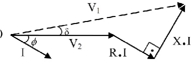
Power systems are basically a collection of nonlinearly coupled systems and generators which supply electric power to loads. A SMIB power system is a simplified dynamic model of complex power systems. As shown in Fig. 1, it composes of a single synchronous generator connected through a transmission line to a very large grid approximated by an infinite bus. The voltage profile of SMIB is pointed out using current and voltage phasors in Fig. 2. The SMIB power system is also a typical nonlinear dynamical system, the control and synchronization of nonlinear behaviours in electrical power systems have great importance from the management point of view to avoid undesirable behaviours such as voltage collapse [15, 24]. Recently, the control, stability and synchronization of nonlinear behaviours in SMIB have been studied. Chen et al. presented the dynamic behaviours of a SMIB power system with bifurcation diagrams, and controlled its chaos with a feedback controller in 2005 [8]. Ford et al. used nonlinear control technique to examine the transient stability problem for SMIB power systems in 2006 [10]. Shahverdiev et al. applied the chaos synchronization in some simple power models including SMIB power system in 2008 [25]. Yang et al. implemented chaos synchronization in SMIB powers system with sliding mode control and applied to secure communication [33]. Chang et al. designed a fuzzy controller to achieve the strict input passivity and Lyapunov stability for the SMIB power system [6]. Wei and Qin controlled the chaos in SMIB power system with adaptive passive control method in 2011 [29]. Ouassaid et al. developed a new nonlinear observer– controller scheme using sliding mode control method and applied to the SMIB power system in 2012 [22].
Figure 1. Single-Machine infinite-bus (SMIB) power system
The aim of this paper is to achieve the non-identical synchronization, anti-synchronization and control of SMIB power system by using active control method. Due to the fact that SMIB power system has second order differential equations, the well-known second order Duffing chaotic system is preferred for synchronization and anti-synchronization. For this purpose, firstly SMIB power system and Duffing oscillator are described and defined as a set of differential equations. Then, the active control, which is a widely-used method for the synchronization of chaotic systems due to its simplicity and success, is applied to these dynamical systems for non-identical synchronization and anti-synchronization. For implementing the control of SMIB power system, synchronization and anti-synchronization signals are summed. Finally, numerical simulations are performed to show the synchronization, anti-synchronization between these two chaotic systems and the control of SMIB power system.
2. System Descriptions
2.1. Single-Machine Infinite-Bus (SMIB) power system
The classical SMIB power system can be defined by the following swing equation as
, ) sin(
max Pm
P D
M
(1)where θ, M, D, Pmax and Pm represent angle of
gene-rator, moment of inertia, damping constant, maximum power of generator and power of the machine, respectively [31]. Also Pm = Asin(ωt) where t is the
time variable, A is the amplitude and ω is the angular frequency of the power of the machine [8].
Taking x = θ and y = , the equation (1) is
equivalent to the following system
), sin( )
sin( ,
t f x cy
y y x
(2)
where c = D / M, β = Pmax / M and f = A / M [8].
(a)
.
(b)
Figure 3. Time series of SMIB power system for (a) x signals, and (b) y signals
Figure 4.x-y phase plane of SMIB power system
2.2. Duffing oscillator
Duffing oscillator is a nonlinear system which describes the hardening spring effect observed in many mechanical problems with a cubic stiffness term. It is one of the extensively studied nonlinear non-autonomous equations, exhibiting various dynamic behaviours, including chaos and bifurcations. The most general forced form of the Duffing equation is
), sin( )
(
3
02
x x x t
x
(3)
where t is the time variable, δ > 0, μ, β, ω and
parameters denote damping coefficient, amplitude of the parametric excitation, stiffness constant, forcing
frequency and the clock, respectively [30]. This equation is used in a number of special forms depending on the parameters chosen. For example, with taking β = 1, ω0 = 1, resetting the clock so that
𝜙 = 0 and using the minus sign, the equation (3) becomes
). sin( )
(x3 x t
x
x
(4)
The equation (4) can be rewritten as a set of two first-order differential equations [20]:
). sin( ,
3
t y
x x y
y x
(5)
a) (b)
Figure 6. x-y phase plane of Duffing oscillator
As shown in Figs. 5 and 6, the Duffing equation (5) represents chaotic behaviour with parameter values
δ = 0.25, μ = 0.4, ω = 1 under initial conditions x(0) = 0.2, y(0) = 0.
3. Non-Identical Synchronization,
Anti-Synchronization and Control of SMIB Power
System
3.1. Synchronization between SMIB power system and Duffing oscillator
In order to observe the synchronization between SMIB power system and Duffing oscillator, we have two above-mentioned systems where the Duffing drive system denoted by the subscript 1 controls the SMIB response system which is denoted by the subscript 2. The drive system is given by
), sin( , 1 1 3 1 1 1 1 t y x x y y x (6)
and the response system is defined as follows:
), ( ) sin( ) sin( ), ( 2 2 2 2 1 2 2 t u t f x y c y t u y x
(7)where u1(t) and u2(t) in system (7) are the control
functions to be determined. In order to estimate the control functions for synchronization, we subtract equation (6) from equation (7). We define the error system as the differences between the Duffing oscillator (6) and the SMIB power system (7) that is to be controlled and the controlling system using
.
,
1 2 2 1 2 1y
y
e
x
x
e
(8)Subtracting equation (6) from equation (7) and using the notation (8) yields
). ( ) sin( ) ( ) sin( ), ( 2 1 1 1 3 1 2 2 2 1 2 1 t u t f y y x x x y c e t u e e (9)
System (9) is called the error system; e1 and e2 are
the error states. The synchronization problem is to ensure the error system (9) asymptotically stable at the origin. Therefore, we define the active control functions u1(t) and u2(t) as follows:
). ( ) sin( ) ( ) sin( ) ( ), ( ) ( 2 1 1 3 1 2 2 2 1 1 t v t f y x x x y c t u t v t u (10)
Then, the error system (9) becomes
). ( ), ( 2 2 1 2 1 t v e t v e e (11)
The error system (11) is linear and the convergent solution can be found under appropriate control input
v1(t) and v2(t) as function of the error states e1 and e2.
As long as the solutions of the system (11) converge to zero as time t goes to infinity, the synchronization between SMIB power system and Duffing oscillator is realized. There are many possible choices for the control v1(t) and v2(t) functions, we take
, ) ( ) ( 2 1 2 1 e e A t v t v (12)
where A is a 2 x 2 constant matrix to be determined. In order to make the closed loop system to be stable, the proper choice of the entries of the matrix A is such that the feedback system must have all of the eigenvalues with negative real parts. Let the matrix A is chosen in the following form
. 1 0 1 1 A (13)
For this particular choice, the closed loop system (11) has the eigenvalues –1 and –1. This choice of control gains will lead to a stable system in which the error states e1 and e2 converge to zero as time t goes to
3.2. Anti-synchronization between SMIB power system and Duffing oscillator
In order to observe the anti-synchronization between SMIB power system and Duffing oscillator, as in the previous section, we have two above-mentioned systems where the Duffing drive system denoted by the subscript 1 controls the SMIB response system which is denoted by the subscript 2. The drive and response systems are the same as in equations (6) and (7) with u3(t) and u4(t) control functions,
respectively.
In this case, we add the drive and response system instead of subtracting:
. , 1 2 2 1 2 1 y y e x x e (14)
This leads to
). ( ) sin( ) ( ) sin( ), ( 4 1 1 3 1 2 2 2 3 2 1 t u t f y x x x y c e t u e e (15)
The anti-synchronization problem is to ensure the error system (15) asymptotically stable at the origin. Therefore, we define the active control functions u3(t)
and u4(t) as follows:
). ( ) sin( ) ( ) sin( ) ( ), ( ) ( 4 1 1 3 1 2 2 4 3 3 t v t f y x x x y c t u t v t u (16)
Then, this implies
). ( ), ( 4 2 3 2 1 t v e t v e e (17)
The error system (17) of anti-synchronization is reached to exactly the same error system of the synchronization in equation (11). We take v3(t) and v4(t) control inputs as before in equation (12). If we
choose the A matrix in the form as (13) for anti-synchronization, we will obtain the same negative eigenvalues –1 and –1 for the closed loop system (17). This choice of control gains will lead to a stable system in which the error states e1 and e2 converge to
zero as time t goes to infinity. Hence, it implies that the anti-synchronization between Duffing oscillator and SMIB power system is achieved.
3.3. Control of SMIB power system
In order to observe the control SMIB power system, we add non-identical synchronization and anti-synchronization signals that are acquired in the previous sections.
The non-identical synchronization of the SMIB power system has the following equation
), ( ) sin( ) sin( ), ( 2 2 2 2 1 2 2 t u t f x y c y t u y x
(18)where u1(t) and u2(t) are the control functions which
provide synchronization to Duffing oscillator. From the equations (10), (12), (13) and (8), they can be calculated as follows:
), ( ) sin( ) ( ) sin( ) ( ), ( ) ( ) ( 1 2 1 1 3 1 2 2 2 1 2 1 2 1 y y t f y x x x y c t u y y x x t u
(19)where the x1 and y1 are the state variables of Duffing
oscillator.
The non-identical anti-synchronization of the SMIB power system has the following equation
), ( ) sin( ) sin( ), ( 4 2 2 2 3 2 2 t u t f x y c y t u y x
(20)where u3(t) and u4(t) are the control functions which
provide anti-synchronization to Duffing oscillator. From the equations (16), (12), (13) and (14), they can be calculated as follows:
), ( ) sin( ) ( ) sin( ) ( ), ( ) ( ) ( 1 2 1 1 3 1 2 2 4 1 2 1 2 3 y y t f y x x x y c t u y y x x t u
(21)where the x1 and y1 are the state variables of Duffing
oscillator.
So that the error dynamics of non-identical synchronization and anti-synchronization of SMIB power system converge asymptotically to zero, the sum of these functions in equations (18) and (20) will lead to a stable system in which the error states converge to zero as time t goes to infinity. The control signals of SMIB power system becomes
), ( ) ( ) sin( ) sin( ) ( ), ( ) ( ) ( 4 2 2 2 6 3 1 2 5 t u t u t f x y c t u t u t u y t u
(22)where u5(t) and u6(t) denote the control functions for
the x and y state variables of SMIB power system, respectively.
Hence, it implies that the control of SMIB power system is achieved.
4. Numerical Results
In this section, numerical simulations are perfor-med to show the non-identical synchronization, anti-synchronization and control of SMIB power system. The fourth-order Runge–Kutta method is used in all numerical simulations with variable time step. The parameters of SMIB power system are taken as c = 1,
(a) (b) (c) Figure 7. Matlab–Simulink modelling of SMIB power system for (a) non-identical synchronization,
(b) non-identical anti-synchronization, and (c) control
(a)
(c)
(b)
(d)
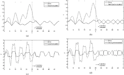
Figure 8. The time response of states for SMIB response system and Duffing drive system with active controllers are activated at t = 25 (a) x signals for synchronization, (b) x signals for
(a) (b)
Figure 9. The time response of the error signals for SMIB response system and Duffing drive system with active controllers are activated at t = 25 (a) synchronization, and (b) anti-synchronization
(a) (b)
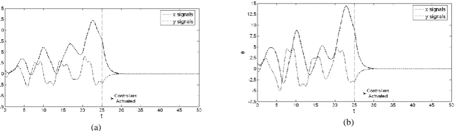
Figure10. The time response of the controlled SMIB power system to E(0, 0) equilibrium point with active controllers are activated at t = 25 (a) x signals, and (b) y signals
The simulation results of the synchronization and anti-synchronization between SMIB power system and Duffing oscillator are shown in Fig. 8: (a) x
signals for synchronization, (b) x signals for anti-synchronization, (c) y signals for synchronization, and (d) y signals for anti-synchronization. The error signals between these systems are illustrated in Fig. 9: (a) displays for synchronization, and (b) displays for anti-synchronization.
As expected, the error signals that are shown in Fig. 9 converge asymptotically to zero. Synchroni-zation and anti-synchroniSynchroni-zation between SMIB power system and Duffing oscillator is observed when t ≥ 29, which verifies the feasibility of the proposed active control method.
The simulation results for the control of SMIB power system to zero equilibrium point are shown in Fig. 10: (a) displays x signals, and (b) displays y
signals.
As expected, the outputs of the SMIB power system converge to the E(0, 0) equilibrium point, after the controllers are activated. As seen in Fig. 10, control is firstly observed when t ≥ 28 with the active controllers, which confirms the effectiveness of the proposed control method.
Although simplified power system model cannot be analysed basically regarding synchronization and anti-synchronization, with a well-known Duffing chaotic oscillator, the SMIB have been easily synchronized and anti-synchronized non-identically to
this system. The related Figs. 8–10 show that the error dynamics converge to zero asymptotically in the non-identical synchronization, anti-synchronization and control of SMIB power system which can be hardly obtained stability condition.
5. Conclusion
[1] H. N. Agiza, M. T. Yassen. Synchronization of Ross-ler and Chen chaotic dynamical systems using active control. Physics Letters A, 2001, Vol. 278, No. 4, 191-197.
[2] C. K. Ahn, S.-T. Jung, S.-C. Joo. A passivity based synchronization between two different chaotic systems. International Journal of Physical Sciences, 2010, Vol. 5, No. 4, 287–292.
[3] E. W. Bai, K. E. Lonngren. Synchronization of two Lorenz systems using active control. Chaos, Solitons & Fractals, 1997, Vol. 8, No. 1, 51–58.
[4] S. Benitez, L. Acho. Impulsive synchronization for a new chaotic oscillator. International Journal of Bifurcation and Chaos, 2007, Vol. 17, No. 2, 617–623. [5] B. Blasius, L. Stone. Chaos and phase synchronization in ecological systems. International Journal of Bifur-cation and Chaos, 2000, Vol. 10, No. 10, 2361–2380. [6] W. J. Chang, C. C. Ku, P. H. Huang. Fuzzy contro-ller design with passivity performance for single machine infinite bus power systems. In: Proc. of Third International Conference on Electric Utility Deregula-tion and Restructuring and Power Technologies, DRPT 2008, Nanjing China, 2008, pp. 2217–2222. [7] D. Chen, R. Zhang, X. Ma, S. Liu. Chaotic
synchro-nization and anti-synchrosynchro-nization for a novel class of multiple chaotic systems via a sliding mode control scheme. Nonlinear Dynamics, 2012, Vol. 69, No. 1-2, 35–55.
[8] H. K. Chen, T. N. Lin, J. H. Chen. Dynamic analysis, controlling chaos and chaotification of a SMIB power system. Chaos, Solitons & Fractals, 2005, Vol. 24, No. 5, 1307–1315.
[9] A. A. Emadzadeh, M. Haeri. Anti-synchronization of two different chaotic systems via active control. Proceedings of World Academy of Science, Engineering and Technology, 2005, Vol. 6, 62–65. [10] J. J. Ford, G. Ledwich, Z. Y. Dong. Nonlinear
con-trol of single-machine-infinite-bus transient stability. Power Engineering Society General Meeting, IEEE, 2006, Vol. 1-9, 525–532.
[11] S.-H. Fu, Q.-S. Lu, Y. Du. Adaptive H-infinity syn-chronization of chaotic systems via linear and nonlinear feedback control. Chinese Physics B, 2012, Vol. 21, No. 6, 060507.
[12] S. Guan, C. H. Lai, G. W. Wei. Phase synchroniza-tion between two essentially different chaotic systems. Physical Review E, 2005, Vol. 72, No. 1, 016205. [13] R.-W. Guo. Simultaneous synchronization and
anti-synchronization of two identical new 4D chaotic systems. Chinese Physics Letters, 2011, Vol. 28, No. 4, 040205.
[14] M. Haeri, A. A. Emadzadeh. Synchronizing different chaotic systems using active sliding mode control. Chaos, Solitons & Fractals, 2007, Vol. 31, No. 1, 119–129.
Y. J. Park. Anti-synchronization of chaotic oscillators. Physics Letters A, 2003, Vol. 320, No. 1, 39–46. [18] C. Li, X. Liao. Lag synchronization of Rossler system
and Chua circuit via a scalar signal. Physics Letters A, 2004, Vol. 329, No. 4-5, 301–308.
[19] G. H. Li. Synchronization and anti-synchronization of Colpitts oscillators using active control. Chaos, Solitons & Fractals, 2005, Vol. 26, No. 1, 87–93. [20] F. C. Moon, P. J. Holmes. A magnetoelastic strange
attractor. Journal of Sound and Vibration, 1979, Vol. 65, 275–296.
[21] A. N. Njah, U. E. Vincent. Synchronization and anti-synchronization of chaos in an extended Bonhöffer– Van der Pol oscillator using active control. Journal of Sound and Vibration, 2009, Vol. 319, No. 1-2, 41–49. [22] M. Ouassaid, M. Maaroufi, M. Cherkaoui. Obser-ver-based nonlinear control of power system using sliding mode control strategy. Electric Power Systems Research, 2012, Vol. 84, No. 1, 135–143.
[23] L. M. Pecora, T. L. Carroll. Synchronization in chaotic systems. Physical Review Letters, 1990, Vol. 64, No. 8, 821–824.
[24] H. Saadat. Power System Analysis. USA: McGraw Hill, 1999.
[25] E. M. Shahverdiev, L. H. Hashimova, N. T. Hashi-mova. Chaos synchronization in some power systems. Chaos, Solitons & Fractals, 2008, Vol. 37, No. 3, 827–834.
[26] V. Sundarapandian, S. Sivaperumal. Anti-synchro-nization of Arneodo chaotic systems by sliding mode control. International Journal of Engineering Science and Technology, 2011, Vol. 3, No. 7, 5740–5746. [27] A. Ucar, K. E. Lonngren, E. W. Bai. Synchronization
of the unified chaotic systems via active control. Chaos, Solitons & Fractals, 2006, Vol. 27, No. 5, 1292–1297.
[28] Z.-L. Wang, X.-R. Shi. Anti-synchronization of Liu system and Lorenz system with known or unknown parameters. Nonlinear Dynamics, 2009, Vol. 57, No. 3, 425–430.
[29] D. Q. Wei, Y. H. Qin. Controlling chaos in single-machine-infinite bus power system by adaptive passive method. In: Proc. of Fourth International Workshop on Chaos-Fractals Theories and Applications, IWCFTA, 2011, pp. 295–297.
[30] E. W. Weisstein. Duffing Differential Equation. MathWorld,
http://mathworld.wolfram.com/DuffingDifferentialEqu ation.html, June 2013.
[31] Z. A. Yamayee, J. L. Bala. Electromechanical Energy Devices Power Systems. New York: John Wiley & Sons, 1990.
[33] Y.-S. Yang, M.-L. Hung, T.-L. Liao, J.-J. Yan. Chaos synchronization in SMIB power system and its application to secure communication. Journal of Physics: Conference Series, Vol. 96, 2008, 012102. [34] M. T. Yassen. Chaos synchronization between two
different chaotic systems using active control. Chaos, Solitons & Fractals, 2005, Vol. 23, No. 1, 131–140.
[35] H.-T. Yau, Y.-C. Pu, S. C. Li. Application of a cha-otic synchronization system to secure communication. Information Technology and Control, 2012, Vol. 41, No. 3, 274–282.