Design and Simulation of a New Universal Reader
Antenna For UHF-RFID Applications
Younes El Hachimi
*, Yassine Gmih, El Mostafa Makroum and Abdelmajid Farchi
University Hassan 1st, Faculty of Science and Technology, Settat-Morocco Laboratory of Engineering, Industrial Management and Innovation.
Date of publication (dd/mm/yyyy): 07/05/2017
Abstract — In this article, a new antenna design for Radio-Frequency Identification (RFID) reader applications in the Ultra High Frequency (UHF) band has been proposed. The antenna is a perfect electrical conductor, excited by a 50 ohms microstrip line, set on an Epoxy FR-4 substrate. His overall size is (98*98*1.6) mm3. We achieve a UHF band antenna by cutting a circular slot on the ground plane and then adjusting the dimensions and position of a rectangle centered in the middle of ground plane. A good impedance bandwidth of 99 MHz has been achieved for UHF band. The antenna show high return loss of -66.12 dB in the center frequency of 0.893 GHz and the gain obtained into simulation of this antenna is 3.16 dB. The Voltage Standing Wave Ratio (VSWR) is less than 2 over the frequency range of 860-960 MHz. The structure design, optimization and simulation results analysis were performed under electromagnetic simulators CST and HFSS, and focused on the return loss, bandwidth, gain and VSWR.
Keywords — Antenna Design, RFID Reader, UHF Band, Return Loss, Gain.
I.
I
NTRODUCTIONThe Radio Frequency Identification (RFID) is a relatively old technology, but it has known a potential growth with a large economic impact on many industrial sectors [1]-[2]-[3]-[4]-[5]-[6]. Compared to other means of identification, RFID has many advantages, such as high recognition accuracy, high speed and the ability to adapt to the environment [7]. With the advancement of the Internet application of Things, as an essential part of sensor network, the application of RFID technology will be more extensive [8].
Generally, an RFID system consists of a reader and a tag, and the reader antenna is an essential part of the reader, which is used to send radio frequency signal from the reader to a tag and receive a backscattered signal from the tag to reader. Therefore, reader antenna plays an important role in RFID systems. Figure 1 illustrates the operation of the RFID system including an RFID tag (also referred to a transponder) and a base station called "RFID reader" [2]-[3]-[5].
RFID systems can involve, according to the frequency band used, four types of applications: LF Applications (125 KHz), HF applications (13.56 MHz), UHF applications ([860-960] MHz) and microwave applications (2.45/5.8 GHz) [1]-[3]-[5]-[6]-[9]-[10].
Fig.1. Principle of an RFID system operation
The frequency ranges for UHF RFID, however, there are several operating bands for different regions, such as North America (902 -928 MHz), Europe (865 - 867 MH), China (840.5 - 844.5MHz, 920.5 - 924.5 MHz), Japan (952 - 955 MHz), India (865 - 867 MHz), Hong Kong (865-868MHz, 920 - 925 MHz), Tai-Wan (920 - 928 MHz), Korea (908.5 - 914 MHz), Singapore (866 869 MHz, 923 - 925 MHz), Australia (920 - 926 MHz), etc. [11].
The microstrip patch antennas have attracted much interest due to their low profile, low fabrication cost, light weight, ease of fabrication and compatibility with printed circuits, but also a number of drawbacks, ranging from narrow bandwidth to low efficiency [12].
In this work, we propose a new design of patch antenna for RFID-UHF reader applications. In the first part, the topology of the antenna is presented. The second part deals the simulation results.
II.
A
NTENNAD
ESIGNThe configuration of the proposed antenna for UHF-RFID applications is presented in figure 2. The antenna consists of a microstrip line, a substrate and a ground plane. The radiating element and the ground plane are PECs (Perfect Electric Conductor) 0.035 mm thick. They are printed on an Epoxy FR-4 substrate, with a relative permittivity = 4.3, loss tangent
𝛿
= 0.025, and thickness h = 1.6mm and the whole antenna size is 98x98x1.6 mm3. The radiator is equivalent to 50 Ohm characteristic impedance and placed at the upper side of the substrate with length of Lf = 69 mm and width of Wf = 6.9 mm, and the ground plane is etched at the opposite side with length of L = 98 mm and width of W = 98 mm.Copyright © 2017 IJECCE, All right reserved
The dimensions of the antenna are listed in table I.
Table I: Parameter details of the antenna (Unit: mm)
Parameter Dimension (mm)
L 98
W 98
Lf 69
Wf 6.8
R1 40.5
n 2.5
P1 41.4
P2 2.8
III.
D
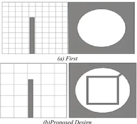
ESIGN STEPSThe design evolutions of the proposed antenna are presented in figure.3. The initial design (a) have a simple microstrip line and circular slot engraved in the center of the ground plane as shown in figure below. In the second one (b), a rectangle is added in the back side and connected to the edge of the circular slot with an angle α=45°. The introduction of circular slot in the ground plane ensures the adaptation of the antenna at the resonance frequency 0.9 GHz and by adjusting the dimensions and position of the rectangle in the ground plane we improve the reflection coefficient. The simulated return loss corresponding to each antenna is depicted in figure 4.
(a) First
(b)Proposed Design
Fig.3. Design evolutions of the proposed antenna
Fig.4. Reflection coefficients for both structures
It is clearly observed from figure 4 that the reflection coefficient of the proposed antenna is better than the first antenna design
IV.
R
ESULT AND DISCUSSIONA.
Return Loss
The design and optimization of the proposed antenna were carried out using the commercial electromagnetic solver CST Microwave Studio. The goal of this study is to design a new antenna structure for UHF-RFID applications with a good return loss by using the slot technique.
To improve the reflection coefficient of the proposed antenna, there are two keys parameters as follow: Modification of the width of the rectangle (n) etched in the ground plane, and Modification of the radius (R1) of the circular slot.
Antenna return loss is the difference between forwarded and reflected power, where antenna efficiency is the measure of electrical losses occurs. In order to design a better performance of an antenna, the value of return loss should be less than -10 dB. The simulated S11 results for different values of n and R1 are shown in figure 5. The parametric studies show that by changing the width of the rectangle etched in the ground plane, the reflection coefficient will be improved (figure 5a), and with increasing the radius R1, the resonance frequencies will be shifted down to lower frequencies as shown in figure 5b.
(a)
(b)
Fig.5. Impact of n (a) and R1 (b) on the return loss of the antenna.
According to the parametric studies, we can conclude that the best results are: n = 2.5mm and R1 = 40.5mm.
the bandwidth extends from 0.867 GHz to 1 GHz thus an extension of about 133MHz.
It can be observed from the figure, an agreement between the results obtained by CST and by HFSS in terms of resonance frequencies and reflection coefficient. The difference obtained is made due to the technique of calculation used in each simulation software. The first one employs the Finite Integration Method (FIM). The second one is based on the Finite Element Method (FEM).
Fig.6. Comparison between parameters S11 found by simulators CST and HFSS
B.
Radiation Pattern
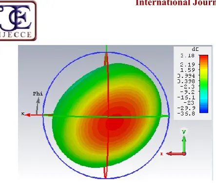
The radiation pattern of the antenna characterizes the variation of radiated power over long distances in different directions in space. Figures 7 and 8 respectively represent the radiation pattern in 2D and 3D. Radiation patterns (2D) in the two plans E (φ=0) and H (φ=90) of the proposed antenna at the several typical frequencies (880GHz- 900GHz- 940GHz) are bidirectional in the E-plane and H-E-plane. The maximum gain (3D) at 0.9 GHz is 3.18 dB.
Fig.7. Measured (2D) radiation patterns of the propose antenna in E-plane (a) and H-plane (b) at 880GHz-
900GHz- 940GHz 940 MHz
880 MHz
900 MHz
940 MHz
(b)
900 MHz
(a)
Copyright © 2017 IJECCE, All right reserved
Fig.8. Measured (3D) radiation patterns of the propose antenna at 900GHz
In order to complete the study of the proposed antenna a calculation of the gain variation over the operating frequency band is performed through the Far Field by using CST-MW. The graph result in figure 9 shows that the proposed antenna provides a peak gain between 860 and 960MHz around 3.06 dB and 3.23 dB.
Fig.9. Plot of gain in dB
C.
Voltage Standing Wave Ratio (VSWR)
To study the adaptation of the antenna which generally reflects the transfer of electric power between the source and the load, an important parameter has been simulated: the Voltage Standing Wave Ratio (VSWR).Figure 10 shows the simulated VSWR of our antenna. The VSWR value is less than 2 over the frequency range of 860-960 MHz, which can easily cover the entire UHF-RFID band.
Fig.10. Simulated voltage standing wave ratio
D.
Comparative Study
In this part, a comparison study of performances, such as reflection coefficient, gain, and dimensions, is made
between our antenna and [13-14]. Table II regroups simulation results of the three antennas. Comparison results show that the proposed antenna exhibits a return loss better than the other ones. Moreover, our antenna has not only a superior gain than the other antennas but also lower dimensions relative to [14].
Table II: Comparative table of the proposed antenna and other antennas [13-14]
Radiation
parameter Proposed antenna The antenna in reference [13] The antenna in reference [14]
Dimensions
(W*L*h) mm3 98x98x1.6 90.5x99.5x1,58 125x96x1.6
S11 (dB) -66.12 -33 -28.57
Gain (dB) 3.18 2.49 2.45
V.
C
ONCLUSIONIn this paper, a novel antenna is designed and simulated over CST Studio Suite based on Finite Integral Techniques. The substrate used for the UHF RFID Reader purpose has a dielectric constant 4.3, loss tangent 0.025 and the substrate thickness of 1.6 mm. The dimensions final of the proposed antenna is 98.5x98x1.6 mm3. Thus, after reviewing all the simulation results, we can conclude that the designed antenna structure can work in UHF RFID system with the frequency bands from 860 MHz to 959 MHz. This design gives as a return loss (<-10) reached at -66.12 dB in the center frequency of 0.893 GHz, a high gain of the order of 3.16 dB and a voltage standing wave ratio less than 2 over the frequency range of 860-960 MHz.
R
EFERENCES[1] M.T. Zhang, Y.C Jiao, M. Koyuturk, F.S. Zhang and W.T. Wang, “Design of Antennas for RFID Application” Book edited by: Cristina TURCU, pp. 554, February 2009, ITech, Vienna, Austria.
[2] Indra Surjati, Yuli KN and Arky Astasari, "Microstrip Patch Antenna Fed by Inset Microstrip Line For Radio Frequency Identifcation (RFID)", 2010 Asia-Pacific International Symposium on Electromagnetic Compatibility, Beijing, China, pp.1351-1353, April 12 - 16, 2010.
[3] E. K. I. Hamad, “Design and implementation of dual band micro strip antennas for RFID Reader applications” Ciência e TécnicaVitivinícola (CIENC TEC VITIVINIC) journal, Vol. 29, 09-2014.
[4] V. kiruthiga, K. Thamarairubini, Sowbakkiyam, K Ramaya, K Ashwin and S. Suresh kumar, “Design and comparative study of meander antenna and micro strip patch antenna,”Vol.3 November 2014.
[5] P. Vikram, H.V Kumaraswamy, R.K Manjunath, "Design and Simulation of Meander Line Antenna for RFID Passive Tag", International Journal of Advanced Research in Computer and Communication Engineering, Vol. 4, Issue 8, August 2015. [6] S. PrakashSinha, M. Kumar, J. Gupta, “Design Of 2x2 Shaped
Rectangular Micro strip Array Antenna For GSM Application” International Journal of Scientific & Engineering Research, Vol. 6, Issue 5, May-2015.
[7] Wu, T.Q., Su, H., Gan, L.Y., Chen, H.Z., Huang, J.Y. and Zhang, H.W. (2013) A Compact and Broadband Microstrip Stacked Patch Antenna with Circular Polarization for 2.45GHz Mobile RFID Reader. IEEE Antennas and Wireless Propagation Letters, 12, 623626.
International Conference on Machine Learning and Cybernetics, Guilin, July 20 II, 330-332.
[9] M. Iftissane, S. Bri, L. Zenkouar, A. Mamouni, “Conception of Patch Antenna at Wide Band” Int. J. Emerg. Sci., 1(3), 400-417, September 2011.
[10] Mahesh M. Gadag, Dundesh S. Kamshetty and Suresh L. Yogi, "Design of Different Feeding Techniques of Rectangular Microstrip Antenna for 2.4GHz RFID Applications Using IE3D", Proc. of the Intl. Conf. on Advances in Computer, Electronics and Electrical Engineering, pp.522-525, 2012. [11] Lin, S.-Y. and Lin, Y.-c. (2012) Printed RFID Reader Antenna
with Circular Polarization for Handheld Operation. Microwave and Optical Technology Letters, 2728-2730.
[12] IBM, "IBM Web Sphere RFID Handbook: A Solution Guide". [13] M. Taouzari, A. Mouhsen, J. El Aoufi, J. Zbitou, O. El Marabat,
“Design of A New Universal Reader RFID Antenna Eye-Shaped in UHF Band”, International Journal of Engineering Research & Technology (IJERT), Vol. 3 Issue 1, January-2014.
[14] M. H. Ariff, I. Ismarani, N. Shamsuddin, “Microstrip Antenna based on Rectangular Patch with Arms and Partial Ground Plane for UHF RFID Readers”, IEEE 6th Control and System Graduate Research Colloquium, Aug. 10-11, 2015, UiTM, Shah Alam, Malaysia.
A
UTHOR'
SP
ROFILEYounes EL HACHIMI was born in 1990. He
received the master degree in Automatic, Signal processing, Industrial Computing from University Hassan first, Settat, Morocco, in 2014.He is currently a PhD student in Engineering, Industrial Management and Innovation research Laboratory, Faculty of Sciences & Technology, Hassan first University, with a thesis on Contribution to the design of RFID antennas. His research interests include antennas, UHF and microwave radiofrequency identification (RFID).
Yassine GMIH was born in 1991. He received the
master degree in Automatic, Signal processing, Industrial Computing from University Hasn first, Settat, Morocco, in 2014. He is currently a PhD student in Engineering, Industrial Management and Innovation research Laboratory, Faculty of Sciences & Technology, Hassan first University, with a thesis on Contribution to the design of RFID antennas. His research interests include antennas, UHF and microwave radiofrequency identification (RFID)
El Mostafa MAKROUM is Professor in the
faculty of the sciences and technology of Settat, Morocco. He received his M.S. degree in 2007 from the Mohammadia School of Engineering, University Mohammed V, Rabat, Morocco. He received his Ph.D. degree in Computers and Telecommunications from the Higher National School of Electricity and Mechanics, University Hassan II, Casablanca, Morocco. His current research concerns RFID antennas, propagation and EMC problems
Abdelmajid FARCHI Ing PhD in Electronis and
Telecommunications Chiefs of research team Signals and Systems in Laboratory of Engineering, Industrial Management and Innovation. Educational person responsible of the cycle engineer Telecommunications and Embedded Systems to the faculty of the sciences and technology of Settat, Morocco.