Final Report
Utilizing Directional Antennas for Ad Hoc Networking (UDAAN)
Defense Advanced Research Projects Agency
Advanced Technology Office
Contract Number:
DAAD19-01-C-0027
Period of Performance:
1 Feb 2001 – 21 Jan 2004
Contract Value:
$ 1,881,637
Prepared for:
DARPA/ATO
Attn: James Freebersyser
Prepared by:
BBN Technologies
10 Moulton Street, Cambridge, MA 02138
Principal Investigator Contacts:
Ram Ramanathan
(
),
Phone: (617) 873-2736
Jason Redi
(
),
Phone: (617) 873-4236
The views and conclusions contained in this document are those of the authors, and should not be interpreted as representing the official policies, either expressed or implied, of the Defense Advanced Research Projects Agency or the U.S.
Table of Contents
1
SCOPE... 3
2
BACKGROUND ... 3
3
UDAAN SYSTEM OVERVIEW ... 5
3.1 Neighbor Discovery ... 5
3.2 Link Characterization ... 6
3.3 Routing... 7
3.4 Forwarding... 8
3.5 Directional Medium Access Control ... 8
3.6 Position Information ... 10
3.7 Security ... 10
4
SIMULATION STUDIES... 10
4.1 JTRS Simulation Study ... 11
5
DIRECTIONAL MEDIUM ACCESS STUDY (UNIVERSITY OF ILLINOIS)... 12
1
Scope
This is a report on the Utilizing Directional Antennas for Ad Hoc Networking (UDAAN) project. The X-MAC project was funded under the DARPA neXt Generation (XG) Communications program (Phase I), beginning in August 2002, and ending in November 2003. The UDAAN project performers were BBN Technologies (Lead Contractor), University of Illinois, Urbana-Champaign (subcontractor to BBN) and Stow Research LLC (subconractor to BBN).
This report contains an overview of the project accomplishments. We emphasize that this report is only an overview, and details can be found in a number of related documents in the distribution including:
1. The UDAAN System Design Document (SDD) [SDD]. This contains the detailed design of the UDAAN system.
2. JTRS Study Report [JTRS-Study]. This contains the results of a simulation study of the performance of UDAAN on a JTRS-2C router system.
3. UDAAN System User Manual [UserManual]. This provides information on how to unpack the software distribution, what the distribution contains, how to run UDAAN simulations, and how to configure the simulations for different conditions.
4. Directional Medium Access Control Study [UIUCReport]. Prepared by University of Illinois, this report addresses a number of problems at the MAC layer that were not considered in [SDD]. Comparative simulation results using the Qualnet simulation tool are also presented.
5. UDAAN Vulnerabilities Assessment [StowReport]. Prepared by Stow Research LLC, this report summarizes the security vulnerabilities of UDAAN protocols.
We note that two other related studies were performed under the UDAAN contract.
1. Hybrid RF/Optical Ad Hoc Network. This study analyzed the network implications of having a hybrid Radio Frequency and Optical Frequency link between nodes in an ad hoc network. The details of this study can be found in [HybridReport].
2. Celestial Internet. This study analyzed the problems in and solutions for providing communication services to satellites. Subtasks were as follows: notional system architecture; detailed technology maturity investigations for necessary components such as cross links, constellation positioning, etc; analytic estimates of throughput; cost estimates for individual satellites and the system as a whole; and detailed simulations of availability and throughput of several constellations. In addition, programmatic constructs such as performer roles, government referees and testbeds, schedules, and cost were suggested.
The remainder of the document is organized as follows. We begin by presenting the background and motivation for UDAAN, and give a statement of the problem. Following that, in section 3 we summarize the main components of the UDAAN system, and then in section 4, give a summary of the experimental results. In section 5 we shall summarize the Directional Medium Acccess Study by University of Illinois, and in section 6 the UDAAN vulernabilites assessment by Stow Research LLC.
2
Background
Over the past few years, research into ad hoc networks has yielded considerable advances, notably in the areas of new routing and medium access techniques.
exploitation by the various components of an ad hoc networking system to address the above problems and provide a significant improvement in network capacity.
Directional antennas have a number of advantages over omni-directional antennas in ad hoc networking. By focusing energy only in the intended direction, directional antennas can increase the potential for spatial reuse and can provide longer transmission and reception ranges for the same amount of power. Increased spatial reuse and longer range translates into higher ad hoc network capacity (more simultaneous transmissions and fewer hops), and longer range also provides connectivity. Further, since the spatial signature of the energy is reduced to a smaller area, chances of eavesdropping are reduced, and with “smart” antennas, the steering of nulls can allow the suppression of unnecessary interference (such as jammers) at the receiver.
Replacing an omni-directional antenna by a directional one in an ad hoc network is not by itself sufficient to exploit the offered potential. The antenna system needs to be appropriately controlled by the each layer of the ad hoc networking protocol stack. Such control includes pointing in the right direction at the right time for transmitting and receiving, controlling the transmit power in accordance with the antenna gains, etc. Further, mechanisms that were designed with omni-directional communications in mind—for example, medium access, neighbor discovery and routing— have to be redesigned for directional antennas. Finally, modifications to such network mechanisms can interact with each other—for instance, medium access control may require knowledge of the antenna beam to use for a particular neighbor discovered by the neighbor discovery mechanism. Thus, in order to realize the full potential of directional antennas, new protocols at various layers of the stack have to be developed and have to work in concert to create a complete system solution.
We present a complete system solution for ad hoc networking using directional antennas, called UDAAN (“Utilizing Directional Antennas for Ad Hoc Networking”). While previous works have targeted specific solutions for directional antennas, such as medium access, there has been no published work on designing, implementing and field testing a complete system that uses directional antennas.
Much of the work on utilizing directional antennas for ad hoc networking has been done in the conext of medium access, in particular in extending CSMA/CA (in particular IEEE 802.11) to work with directional antennas. This includes [Takai-Mobihoc02] and [Choudhary-Mobicom02]. Medium access approaches are also discussed in [Ramanathan-Mobihoc01].
A small amount of work exists in the area of TDMA using directional antennas [Dyberg-Milcom02][Bao-Mobicom02]. In [Dyberg-Milcom02], the authors study the performance of ad hoc networks with a TDMA MAC and two kinds of beamforming antennas—beam steering and adaptive beamforming. In [Bao-Mobicom02], a distributed algorithm is given that only uses 2-hop information for scheduling, thereby making it scalable, yet implementable for mobile ad hoc networks.
The study of directional antennas for aspects of ad hoc networking other than medium access is limited. The use of directional floods to limit the scope of route requests in an “on-demand” ad hoc routing protocol is suggested in [Ko-Winet], and explored in [Nasipuri-ICCCN]. A broad-based study of the performance potential of directional antennas in ad hoc networks appears in [Ramanathan-Mobihoc01].
Thus, the state of the art before UDAAN was restricted to “point solutions” for specific problems. In particular, a number of problems that arise in the development of a complete system solution were not addressed. Our work extends the state of the art significantly by developing a complete ad hoc networking system for directional antennas and studying it using simulations. In particular, we have developed several novel mechanisms for directional antenna support including
• A novel CSMA/CA based medium access control for directional antennas based on directional carrier sensing, integrated power and direction control, event specific backoffs, etc.
• Neighbor discovery using transmit-only or transmit-receive beamforming, including novel ``blind'' searching techniques.
• Link characterizatio and metric estimation for QoS-sensitive routing in the presence of directional antennas.
These and other mechanisms need to interact in a number of ways for the system to function as a whole. Significant research issues arise in doing so. A noteworthy contribution of this work is a design approach where the interactions have been successfully worked out in a system context.
The UDAAN system outlined in this report has been implemented on real hardware, and supports both switched and steered antennas. The UDAAN hardware prototype that we have developed and demonstrated consists of fixed antennas, a switch fabric for switching between antennas, a radio transceiver, and processors that run the UDAAN software. We have conducted experiments with this prototype system.
Using a novel portable software framework, we have run simulations using the same code as in the prototype. Using this, we have simulated several scenarios including a replica of our real-life tests. Both simulation results as well as our field demonstrations show that UDAAN signficantly outperforms omni-directional communications.
3
UDAAN System Overview
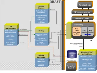
The UDAAN system is composed of a set of interacting mechanisms at the networking and MAC layers, as illustrated in the figure below. The system consists of a set of network layer modules - link characterization, neighbor discovery, routing, and position information - which are implemented in an operating system independent manner. The MAC and some parts of the Forwarding module are system specific. Application packets (transit or originated) are forwarded using an appropriately chosen next-hop forwarding table. We present a brief overview of each module.
Figure 1 - UDAAN Architecture
We now describe each component very briefly. A detailed description can be found in [SDD].
3.1
Neighbor Discovery
transmit/receive properties that have been found to be sufficient for closing the link. Currently, a link profile has two fields – band, and mode. For convenience we speak of two bands - high and low – (though the implementation actually supports up to 32 bands) and there are three modes – No Beamforming (N-BF), Transmit-only Beamforming (T-BF) and Transmit-and-Receive Beamforming (TR-BF). Thus, we allow up to 6 link profiles per neighbor. (The implementation will actually support 3 modes x 32 bands = 96 link profiles per neighbor.) The neighbor discovery module establishes and maintains the “status” of each link profile and each neighbor. It does so by periodically sending heartbeats (Hello/Beacon packets) and “scoring” received heartbeats. A link profile is declared up if and only if it is bidirectional. Notification of a link profile up/down status change is communicated to the link characterization and routing modules.
Neighbor discovery utilizes two classes of techniques to discover potential neighbors:- Non-Beamformed (N-BF) and Beamformed (BF). N-BF techniques ideally use the antenna pattern covering the largest possible volume and is similar to traditional neighbor discovery techniques, such as the one in the DARPA GloMo DAWN [DAWNReport] project. Beamformed techniques can be further subdivided into Transmit only Beamforming (T-BF), where only the transmitter beamforms, and Transmit-Receive beamforming (TR-BF) where both transmitter and receiver beamform.
The techniques may be additionally classified as Informed or Blind. Informed beamforming is employed when a node knows about the existence of potential neighbors through some means (such as a different band or from the link-state database). Blind beamforming is employed when there is no information available about a potential neighbor. We simply search for any node that is “out there.”
Each technique may operate in any band. Each technique is largely independent of the others, but may use information obtained using other techniques in establishing its own link profile. For instance, T-BF neighbor discovery may target a neighbor heard through N-BF and attempt to establish a (presumably higher capacity and better quality) link profile through transmit beamforming.
The neighbor discovery module maintains a neighbor table, which contains the list of nodes considered as neighbors (currently or in the recent past). For each neighbor, a number of items of information are maintained for use by the neighbor discovery module and by other modules. In particular, the status of the neighbor (e.g. active/inactive) and all associated link profiles are stored.
In sum, neighbor discovery implements mechanisms for determining when a neighbor becomes active or inactive, and for maintaining the set of link profiles associated with a neighbor. The neighbor discovery module sends an IPC message to the link characterization and the routing modules whenever a link profile is added or deleted.
3.2
Link Characterization
The function of the link characterization (Linkchar) module at each node is to evaluate the characteristics of each link profile in terms of various metrics (e.g. delay, signal quality, interference caused, etc). It does so by gathering and analyzing tracerecords of transmitted and received packets. Such tracerecords are available from the link layer, which creates these based on interactions with the physical layer. The link characterization module will also generate its own probe packets under certain circumstances, to augment data from other packet sources. The analysis uses predictive filtering techniques to estimate the metrics, whose values are changed periodically to reflect the changes in the link profile characteristics, and conveyed to the routing module upon significant change. The neighbor discovery module may also query link characterization concerning the state of a link from which it has not heard sufficiently many heartbeats.
The Linkchar module is designed to take information from the link layer interface and from peer Linkchar modules in neighboring nodes in order to provide a summarized set of link and node characteristics or metrics. These metrics will then be used by routing to create paths and determine the correct power to use for transmissions to next-hops. Linkchar’s actions are also used by the neighbor discovery module in the case of when the neighhbor discovery module has not heard heartbeats for a while and requests Linkchar’s “opinion” of the link (usually via a “probe”).
(N-BF, T-(N-BF, TR-BF). Since different beam steering methods and transmission bands will show different link characteristics, there will be a set of link metrics for each link profile. Note that there are both node metrics, such as congestion, and link metrics, such as energy. All the link metrics are defined as representing the outgoing cost from this node.
All metrics are calculated based on tracerecords. Changes in the metrics are only reported to the routing module and only if dneighbor has indicated that this particular link profile is “tracked”. The link characterization module does not send periodic heartbeat messages to test the link. The only packets that Linkchar will send out the radio are “probes” to determine whether a neighbor is still there when passive methods (e.g. observing transmits and receives via tracerecords) have failed.
The following are the link metrics that are reported for each link profile:
• Required Energy (dBm) – This is an estimate of the minimum amount of transmit power required to close the link to the neighbor. This value is used by droute to fill in radio profiles to indicate to the link layer what power level should be used to send packets. This value is determined by considering packets which have been received from that neighbor, along with the transmit antenna pattern, receive antenna pattern, and the transmit power. Note that we need to back out the antenna gains based on the direction that each of the fixed antennas was pointing at the time the packet was sent. A change in this value doesn’t necessarily cause droute to generate a new LSU, because the energy is only used for the radio profiles, and not used for building routes.
• Link Profile Status – This is a metric that is based on the required energy metric as well as second order statistics of that metric. The result is a small integer number that indicates whether this link profile is “excellent”, “good”, “marginal”, or “bad”. Besides a subjective description of the link, this status provides a value for droute to use for routing. We don’t use the energy directly because that can change quite widely and would therefore cause a huge amount of LSU overhead. Instead we use this “coarsened” version of the energy which provides us rough guidance as to the quality of the link. (Recall that energy dictates bit error rate and therefore also the reliability and potential throughput on a link).
• Delay – The delay metric is not implemented within UDAAN, but a “delay” metric is still reported to droute. The delay metric is settable via configuration so this is currently used for hardwired setting of the metrics for particular links.
The following attribute is a node metric, which is reported for each band available in a node, and can be reported regardless of whether a node has any operational links:
• Congestion – Using the amount of transceiver utilization due to network overhead as well as data traffic, this metric estimates the percentage of available transmission or reception time at a node’s radio. The measurements are based on long-term observations to reduce fluctuations. This value is not used directly but is added to another metric (depending on configuration) to bias against similar paths that have high traffic utilization.
3.3
Routing
The function of the routing module at each node is to generate routes to each destination and, to create and update next-hop forwarding tables for use by the forwarding module. Route generation utilizes the metrics assigned by the link characterization module to support QoS-based routing. The routing scheme used is “proactive” and based on a scalable variant of link-state routing called Hazy Sighted Link-State Routing (HSLS), which was developed as part of the DARPA GloMo Density- and Asymmetry-adaptive Wireless Network (DAWN) project. HSLS limits the propagation of link-state updates so that the timeliness of the information is a linear function of the number of hops. HSLS is a simple, non-hierarchical, scalable routing protocol that is well studied and understood. The routing module generates a next-hop forwarding table for each type-of-service (TOS). For each entry in each table, it also determines the values (i.e. the “radio profile”) the radio and antenna controllers must use to send to that neighbor to meet the ToS requirements.
Sighted Link State (HSLS) algorithm (see pseudo-code in figure R1), in which the Time To Live field of a LSU packet may be set to 1, 2, 4, 8, ..., or to the special value (255) that is interpreted as meaning `infinity’. A LSU with a TTL set to `infinity’ will not have its TTL value decreased by nodes retransmitting it, so the LSU could continue to be transmitted forever. However, a node only processes and retransmits a LSU once. Duplicated LSUs are detected thanks to their sequence number field. Thus, LSUs with TTL set to infinity will be processed and retransmitted exactly once per every node in the network. For this reason, we refer to LSUs with TTL set to infinity as global LSUs. In the other extreme, an LSU with TTL set to 1 is said to be a local LSU. All the other types of LSUs are referred to as simply LSUs.
HSLS is a variant of link state that allows for scalability with size/mobility/traffic. In HSLS each node’s topology table, although global, may be unique to that node, since different nodes may have different views of the network at any given time. A more detailed description of HSLS can be found in [SDD].
The main sub-modules of Routing are:
• Update generation - Triggers (according to HSLS rules) a new LSU update upon a significant change of link state.
• Update dissemination - Retransmits LSUs generated by other nodes.
• Topology database maintenance - Validates/updates/adds/removes entries in the Topology table.
• Route computation - Builds a route toward each destination, based on QoS metrics.
• Next_hop table construction - Creates tables with an entry per each possible destination. The fields of each entry specify the neighboring node to which packets for a given destination should be forwarded, and the link profile to be used for reaching that node.
3.4
Forwarding
The function of the forwarding module at each node is to, upon receiving an originated or in-transit packet, look up (based on the destination) the next-hop entry in the relevant table (based on the ToS), and send the packet to the link layer along with the radio and antenna parameters that must be used, including the band and the beamforming mode (e.g. T-BF).
3.5
Directional Medium Access Control
The Directional MAC module receives the packet from the forwarding module and sends it out for transmission to the physical layer through the Transceiver API after performing the media access control functions. The MAC protocol is based on “unscheduled access”. Unlike TDMA schemes, no slot synchronization is required at the physical layer. Also, unlike TDMA schemes that may require a re-alignment of slot allocations as the nodes move, this approach adapts well to mobility. The MAC is similar to the IEEE 802.11 DCF in terms of the control primitives used, namely the RTS/CTS/Data/Ack handshake for sending a packet. However, there are significant differences, especially with respect to the backoff mechanism, the dynamic selection of antenna patterns controlled by the D-MAC, and the Node Allocation Vector (NAV). We give a brief description of the baseline protocol below. This baseline has been extended in a number of ways, some of which have been implemented and some of which have not – for details please refer [SDD].
The D-MAC has two transmit modes, each with two transmit sub-modes, as described below.
•
Unreliable. The unreliable mode does not provide any indication of success or failure. No acknowledgement is expected from the receiver. There are two unreliable sub-modes•
Without RTS. In this case, the sender sends the DATA without any accompanying primitives.•
Reliable. The reliable mode guarantees to the router an indication of delivery or failure. To allow this to happen, an acknowledgement is sent by the receiver in response to every DATA packet. There are two reliable sub-modes.•
Without RTS. In this case, the sender sends the DATA and the receiver sends an ACK upon receipt of the DATA. We expect this to be used for small packets (below a pre-configured threshold, as determined by the router and indicated by the radio profile).•
With RTS. In this case, the sender sends an RTS, the receiver sends a CTS, then the sender sends the DATA and the receiver sends an ACK. We expect this to be used for all but small packets.Thus, there are four types of packet transfer modes possible. The desired mode is selected by the router using a bit field in the radio profile which indicates which of use(RTS/CTS/ACK) are to be used. If the useACK bit is set, then the mode is reliable, else it is unreliable. The RTS bit then specifies the sub-mode (within the mode) is as given above. In the current specification, the useCTS bit is ignored.
The D-MAC is by default in idle state. In this state, the D-MAC is in receive mode, switched to the omni antenna. When a packet is to be sent, either initiated locally (including forwarded packets), or as a response to an RTS, the D-MAC exits the idle state.
Point-to-point DATA packets are transmitted and received directionally, using the antenna presumed to have the maximum gain toward the sender/receiver. Before initiating transmission of a new packet or an RTS thereof, directional carrier sensing is used to determine whether the corresponding antenna senses the channel is busy or not. If the channel is busy, then the node returns to idle mode (switches to the omni antenna) for a short random period of time before sensing the channel again. The random period of time between consecutive sensing periods is kept flexible – it may be adjusted using different algorithms to yield different variants of the same general strategy.
If the antenna is found to be free, the packet is transferred. The exact nature of primitives exchanged to transfer the packet depends upon the mode/sub-mode requested for the packet. For instance, to transfer a packet reliably using RTS, an RTS-CTS-DATA-ACK handshake is used. In this case, all primitives (RTS, CTS, DATA, ACK) are transmitted directionally. The CTS, DATA and ACK are received directionally. The antenna used is obtained using a lookup method that maps the RF MAC address to the antenna number. All primitives not intended for the node are ignored for MAC protocol purposes, but may be sent to the router for link characterization.
In case of non-receipt of CTS or ACK, a node backs off randomly, switching to the omni antenna while backing off, and tries again. If the ACK is received, indicating successful packet transfer, the node is still obligated to wait for a certain time before initiating another packet transmission. Finally, and as mentioned earlier, if a node finds the channel busy during the directional carrier sense, it backs off randomly.
Thus, there are four situations – channel is busy on directional carrier sensing, no CTS is received, no ACK is received, successful completion of the transfer – when the node may have a packet to transmit, but is prevented from doing so by the protocol for a specified period. This period is referred to as a forced idle period. Depending upon which of the four situations caused the transition into the forced idle state, the forced idle period is different. When in forced idle mode, the node should respond to RTSs, and complete reception of packets intended for itself, but should not initiate its own RTS/DATA.
The performance of the protocol depends significantly on the scheme used to compute the forced idle (essentially backoff) intervals. Initial schemes for each situation are specified in this document, but it is possible that they may need to be modified for different environments.
3.6
Position Information
The function of the position information module at each node is to obtain the geographical position of that node using an interface to a “Navigation Control” as shown in Figure 1, above. The navigation control, which is outside the scope of UDAAN might obtain the position using GPS or other means. Additionally, the peer position information modules exchange information so that the positions of all nodes in the network are available locally. The position information module may also receive position information from the Routing module or by other means. It updates the direction table in the MAC module upon changes of more than a given threshold in the relative direction. The direction is computed in relation to a fixed direction, e.g., due east. We assume that the antenna controller tracks the rotational frame of reference, so that the beam can be pointed in the right direction, regardless of the orientation of the platform.
3.7
Security
Authentication and timestamps are used to prevent spoofing, spread of stale information, and replay attacks. All UDAAN control messages, with the exception of MAC messages, contain a digital signature (based on public-key cryptography) over a one-way hash of message contents. The signature is verified at each destination for the message. Each message also contains a timestamp (time obtained using GPS, for instance). Timestamps are verified to be within an acceptable window at each destination. Messages with unacceptable timestamps are dropped. MAC messages do not contain such features, since their small size - required for low collision probability - precludes the use of timestamps and signatures.
4
Simulation Studies
We performed a simulation study of the UDAAN system using the OPNET simulation tool. We present the highlights of our results here. Details, including plots, can be found in [WCNCPaper].
The UDAAN model is based on the Portable System Framework (PSF) and OPNET. OPNET has a detailed propagation model where the bit error rate on a packet is computed based on the signal to interference and signal to noise ratios. The propagation model is implemented by means of several pipeline stages that were augmented, for instance, to support packet processing when antenna switching occured in the middle of its reception.The use of the PSF allowed us to use the same networking code (except for MAC) in our simulations, as in the testbed. Thus, the simulations are very high fidelity. The downside is that simulations take very long to run, thereby reducing the number of data points that can be generated in a given time.
We have run our simulations both on two specific scenarios, and on many randomly generated scenarios. We describe each below.
• Specific Scenarios. The goal here was to replicate the real-life demonstrations conducted as part of the FCS Communications Phase II program. A tool called OPAR from MITRE Corp. was used to model the path loss between the nodes. OPAR uses a 2-ray ground reflection propagation model augmented by specific pathloss models for foliage, buildings, etc. Such obstacles are modeled by using polygons with specific propagation characteristics. Thus, two nodes that have foliage between them will typically have severe attenuation, and nodes with buildings between them will typically have no connectivity at all.
• Randomly generated scenarios. The goal here was to excercise UDAAN over a wide range of network densities and mobilities and understand the trends in performance, in particular the difference between omni-directional and directional antennas. All simulations are with a 20 node ad hoc network. The nodes are placed randomly in a 2-dimensional square area of varying size depending upon the density parameter. Mobility is similar to the random waypoint model, but nodes do not stop at waypoints. For further details on these scenarios, please refer [WCNCPaper].
1. The difference between omni-directional and directional communications was wider with the Demonstration 2 scenario than with the Demonstration 1 scenario. Specifically, in the Demonstation 1 scenario, there was only a marginal difference in the throughput and delivery ratios of omni and directional antennas, and the use of T-BF did not appear to help much. In contrast, using Demonstration 2 scenario, the directional antennas perform considerably better than omni-directional antennas - about 14% better in delivery ratio, which is good for realistic traffic. The use of T-BF in this case does help, by about 11%. It thus appears that the effect of longer-range links is significant.
2. With a steered antenna of gain 26 dBi, the throughput is increased by a factor of about 8 (at higher densities) to a factor of about 10 (at lower densities). The main reason for the large throughput difference at lower densities is due to the network being disconnected when omni-directional antennas are used, but well connected with omni-directional antennas.
3. The throughput for both directional and omni-directional antennas was largely unaffected by speed, probably because for the range of speeds tested, the hazy sighted link state routing was able to adapt quickly enough.
4. We compared the throughput using switched and steered antenna models as a function of antenna gain. An important fact to note here for the switched antenna curve is that the number of antennas is kept constant. Thus, when gain is increased (and beamwidth is decreased), the azimuthal ``coverage'' (the fraction of the 360 degree plane with at least 0 dBi gain) goes down. Interestingly, as gain increases, the performance of switched antenna still increases upto a certain gain value (10 dBi) indicating that the increased gain makes up for the lost coverage. But after that the decreased azimuthal coverage starts to hurt us. For steered antennas, this issue does not arise as the beam can be pointed wherever desired. Thus, the performance continues to increase with gain. Predictably, steered antenna provides better throughput than switched antennas, but the difference is not high at low gains (and probably won't be at higher gains too, if the number of switched antennas is increased commensurately).
4.1
JTRS Simulation Study
We performed a simulation study whose aim was to investigate the likely effects of using directional antennas with a JTRS-2C router system. Since JTRS-2C does not currently support directional antennas, we chose to use the UDAAN router system as a surrogate.
We began with a direct comparison of JTRS-2C and UDAAN in the case when both use omni antennas. We then additionally simulated the same scenarios for UDAAN with directional antennas. This set of simulations allowed us to see the effect of directional antennas in scenarios where JTRS-2C performance can be measured.
Next we observed the performance of UDAAN as we varied the number of nodes that use directional antennas. Finally, we performed full-length simulations of the FCS Comms Lakehurst Dmo1 scenario for JTRS-2C, UDAAN with omni-only antennas, and UDAAN using directional antennas.
The study used existing models of both JTRS-2C and UDAAN protocols. The parameters of these OPNET models were set so as to provide the best comparison possible, without significantly modifying the models. Both models are high fidelity and do not use any “abstractions” of protocol behavior.
We conducted three sets of experiments
antenna model was used for all runs. The runs using 12 antennas additionally used idealized directional antennas, with nominal 30 degree beam width.
2. In the second experiment only UDAAN nodes were simulated, but some of the nodes used omni-directional antennas only, while others additionally used omni-directional antennas. This experiment used idealized directional, idealized omni antenna models. The directionally-enabled nodes made use of 12 directional antennas (each with a 30 degree beam width).
3. In addition to the above experiments we performed three complete simulations using the FCC Comms Lakehurst Scenario #1. This is the scenario used for the FCS Comms Demonstration 1, done at Lakehurst, NJ in February 2002. The 3 systems simulated in these runs were: JTRS, UDAAN with omni antennas only, and UDAAN with directional antennas. Each Lakehurst run simulated approximately 1 hour and 20 minutes.
Details of the simulation set up and results, including charts, can be found in [JTRS-Study]. It was concluded that directional antennas improve performance for UDAAN and would do so as well for JTRS-2C
5
Directional Medium Access Study (University of Illinois)
A directional MAC study was performed by subcontractor University of Illinois, at Urbana-Champaign (UIUC). The objective of the study was to perform simulation analysis of the BBN Medium Access Control mechanism (see section 3.5), and to study a number of variants of the mechanism and a number of novel features.
All simulation work was performed using the QualNet simulation tool. In particular, the following studies were done.
1. An evaluation of the BBN medium access control mechanism.
2. A novel method using multi-hop RTS for establishing TR-BF links in a connected network was developed. The protocol was specfied and performance evaluation done. In addition, some issues affecting directional communication were discussed.
3. A MAC protocol that uses two channels was developed (called DualMAC). The performance of this protocol was analyzed.
4. A mechanism for location (position) information managment in directional antenna based ad hoc networks was presented and evaluated using simulation.
5. Priority scheduling methods previously developed by UIUC was adapted for use with directional antennas, and its performace was evaluated.
We refer the reader to [UIUCReport] and [Roychoudhary02] for a more detailed exposition of this work.
6
UDAAN Vulnerability Analysis
A UDAAN vulnerability analysis report was performed by Stow Research LLC [StowReport]. This report describes, for each of the UDAAN protocols, the perceived vulnerabilities to a wide range of denial-of-service attacks and, in the cases where vulnerabilities exist, the recommended countermeasures to reduce the probability of and the damage caused by a successful attack. For the purposes of this discussion, the UDAAN protocols are those UDAAN control functions that send and receive packets as part of their basic operation. Directional medium access control (MAC), neighbor discovery, hazy-sighted link-state routing, and data-packet forwarding constitute the UDAAN protocols. Link characterization and route selection are UDAAN control functions but do not send or receive packets and hence are not considered to be UDAAN protocols.
• Response to detected anomalies
• Packet Semantics
• Detection of temporal errors
Protocol specific countermeasures were designed for the following UDAAN modules
• Directional medium access control: Specific countermeasures were designed for lost packets, masquerades, falsified parameters, replays, repeaters, and clock errors.
• Neighbor discovery: Specific countermeasures were designed for lost packets, falsified parameters, replays, repeaters, and ideas for reducing heartbeat frequency to be less detectable.
• Routing: Specific countermeasures were designed for lost packets, falsified parameters, delays, repeaters.
• Forwarding: Specific countermeasures were designed for lost packets, falsified parameters, replays, congestion, misdirection of packets.
For a detailed exposition of the vulnerabilities and solutions, please refer to [StowReport].
7
Publications
Two conference papers have been published from this project [WCNCPaper] and [MilcomPaper]. In addition, one journal paper [JSACPaper] has been submitted for publication.
References
Note: The documents [SDD], [JTRS-Study], [UserManual], [UIUCReport], [StowReport], [HybridReport], are present in the final UDAAN distribution. Any of these documents may be obtained by sending email to
[email protected] or [email protected], or [email protected].
[SDD] BBN Technologies, “Utilizing Directional Antennas for Ad Hoc Networking (UDAAN),” System Design Document, Version 5.0, January 2004.
[Study] BBN Technologies, “Estimating the Effect of Directional Antennas on the Performance of JTRS-2C Router Systems, November 2002.
[UserManual] D. Wiggins, “UDAAN User Manual”
[UIUCReport] Nitin Vaidya (PI, UIUC), “Utilizing Directional Antennas in Ad Hoc Networks, Final Report” [QUALNET] http://www.qualnet.com
[StowReport] Martha Steenstrup, “UDAAN Vulnerabilities and Solutions”
[HybridReport] G.Troxel, J. Zinky, “Networks of Hybrid Optical/RF Links”, April 16, 2003
[DAWNReport] BBN Technologies, “Density and Asymmetry Adaptive Wireless Networking (DAWN) Final Report”
[GuptaKumar] P. Gupta and P.R. Kumar, ``The Capacity of Wireless Networks'', IEEE Transactions on Information Theory, vol. IT-46, no. 2, pp. 388-404, March 2000.
[Choudhary-Mobicom02] R.R. Choudhury, X. Yang, R. Ramanathan, N. Vaidya, ``Using Directional Antennas for Medium Access Control in Ad Hoc Networks,'' Proc. ACM MOBICOM, Atlanta, Georgia, September 2002. [Ramanathan-Mobihoc01] R. Ramanathan, ``On the Performance of Ad Hoc Networks with Beamforming Antennas,'' Proc. ACM MobiHoc, Long Beach, CA, October 2001.
[Dyberg-Milcom02] K. Dyberg, L. Farman, F. Eklof, J. Gronkvist, U. Sterner, J. Rantakokko, ``On the Performance of Antenna Arrays in Spatial Reuse TDMA Ad Hoc Networks,'' Proc. IEEE MILCOM, Anaheim, California, October 2002.
[Bao-Mobicom02] L. Bao, J.J. Garcia-Luna-Aceves, ``Transmission Scheduling in Ad Hoc Networks with Directional Antennas,'' Proc. ACM MOBICOM, Atlanta, Georgia, September 2002.
[Ko-Winet] Y-B. Ko and N.H. Vaidya, ``Location-Aided Routing (LAR) in Mobile Ad Hoc Networks'', ACM/Baltzer Wireless Networks (WINET), Vol. 6, No. 4, pp. 307-322.
[Nasipuri-ICCCN] A. Nasipuri, J. Mandava, H. Manchala, and R.E. Hiromoto, ``On-Demand Routing Using Directional Antennas in Mobile Ad Hoc Networks,'' in Proceedings of the IEEE International Conference on Computer Communication and Networks (ICCCN2000), October, 2000, Las Vegas.
[WCNCPaper] R. Ramanathan, J. Redi, C. Santivanez, D. Wiggins, S. Polit, “Ad Hoc Networking with Directional Antennas,” Proc. WCNC, Atlanta, 2004.
[MilcomPaper] J. Redi, R. Ramanathan, “Utilizing Directional Antennas for Ad Hoc Networks,” Proc. IEEE Military Communications Conference (MILCOM), 2002.