Paper received: 12.1.2007 Paper accepted: 19.12.2007
Artificial Neural Networks Application in Duplex/Triplex
Elevator Group Control System
C. Erdem Imrak
Istanbul Technical University, Turkey
Artificial neural networks can offer the better solution to the passenger call distribution problem when compared to the conventional elevator control systems. Therefore, the application o f neural networks in elevator group control system is discussed. The significance o f introducing artificial neural networks is presented. Elevator group control systems with neural networks can predict the next stopping floors to stop by considering what has been learnt by processing the changes in passenger service demand pattern. This paper deals with the use o f artificial neural networks fo r the distribution o f the most suitable cars to the floors by considering the passenger service demand. Artificial neural networks are applied in Duplex/ Triplex group control systems fo r improving passenger waiting time. The backpropagation algorithm is used fo r training neural networks. The elevator traffic analysis and simulation results are presented and compared to conventional elevator control systems.
© 2008 Journal o f Mechanical Engineering. All rights reserved.
Keywords: elevators group control systems, neural networks, backpropagation
0 INTRODUCTION
The service provided by the elevator system o f any modem building is necessary for the efficient functioning o f the building. This service has to be not only reliab le, but also satisfacto ry to the passengers. Elevator group control systems can be utilized to control the cars as a group and convey the passengers to their destinations comfortably and promptly. It is viewed as a combination o f on-line scheduling, resource allocation and stochastic optimal control problem s sim ilar to robotics or auto m ated m a n u factu rin g system s. H ow ever, elevator control systems are harder to deal with than other systems because the states o f the system are dynamically changed in large state space and coming events are unpredictable in many cases [1]. In offering a solution to elevator control problem, the tra d itio n a l c o n tro l sy ste m s o fte n y ie ld u n s a tis fa c to ry re s u lts b e c a u se th e y la c k in considering number o f technical characteristics and possibilities to be taken in to account. They also possess lim itations and their flexibility is still re stric te d ev en i f th ey are adapted to u tilize computers. The selection and distribution o f the most suitable cars in the building is a function of the call assignment. Landing and car calls are often allocated to suitable cars by taking into account of
the m in im u m co st co n cep t th a t o p erates by performing a trial allocation to all available cars and allocating the call to the car giving the lowest cost. The criteria for determining a suitable cost function depends on either quantity o f service and/ or quality o f service. The quality o f service is a measure o f the elevator capacity consumed to serve a specific set o f calls, indicated by total journey times o f all the cars [2].
Elevator control problem has been studied for a long time: in the last two decades artificial intelligence techniques such as fuzzy logic, neural netw orks, genetic algorithm s and evolutionary algorithms were introduced. Although considerable research studied has been carried out to explore artificial intelligence applications in elevator control area [3] to [9], a little work has been done in neural network application in elevator group control.
Neural networks have been applied to tackle the selection and distribution o f the most suitable cars which is a function o f assignment o f calls. Artificial neural networks which simulate the way that human neural networks operate and learn, and m imic the hardware structure o f the brain in a simplified way consist o f artificial neurons that perform a simple task and are fully interconnected [ 1 ]. A neural network is used to predict the number
o f landing calls likely to be made and the cars’ likely destination for the time o f service in order to o p tim ize the car allocation efficiency. The prediction is made by combining predictions from historic data leamt during corresponding periods o f previous days and real time data leamt during a short interval. They can be envisaged as a black box acting in response to a set o f inputs o f position, direction and calls produces an output representing the next stopping floor. Artificial neural networks can be placed in the conventional control system to improve the elevator performance [11].
In this study, the artificial neural networks has been inserted into an elevator group control system s for m inim izing the average passenger w aiting time and developed to model the behavior o f the building population and also to adapt the algorithm to changes in passenger demand. For training the neural networks, the backpropagation m ethod was used in the present work. The aim of th is a p p lic a tio n is to o p tim iz e so m e o f the p a ra m e te rs that a c o n tro lle r u ses in o rd er to m inim ize the average passenger waiting time. The d a ta used here are from a sim u lato r program developed by the author [9], The elevator traffic analysis has been carried out using the software w ritten in Turbo Pascal version 7.0 by examining the simulation results obtained. Simulations are run for several levels o f interfloor traffic demand for the improved Duplex/Triplex control system (ICS). In the sim ulation an existing building having 3 elevators with 10 floors was selected as a model case. The normalized perform ance figures, w ith respect to the interfloor demand, are compared to other traffic control algorithms which are priority tim ed fixed sectoring algorithm (FSPTS), the fixed sectoring common sector system (FSCSS).
1 STRUCTURE OF THE ELEVATOR GROUP CONTROL
Building traffic becom es m ore and m ore diversified and complicated as building has more various functions and intelligence. Elevator group c o n tro l a lg o rith m , th e re fo re , b e c o m e m o re complicated as they become more intelligent. The goal o f elevator control is to provide operational management o f a group o f elevators, by selecting cars to meet landing calls and achieve passengers’ destinations pleasantly and promptly. An efficient elevator control system has four properties [2]: to
provide even service to every floor in a building, to minimize the passenger journey time in the car, to m inim ize the passenger w aiting time, and to serve as many passengers as possible given time. The basic function o f elevator control system is to assign an appropriate car to occurred landing calls to quickly respond them. The car to be assigned will be selected with consideration o f many factors such as passenger waiting time, passenger journey tim e and en erg y co n su m p tio n . A m ong th em passenger waiting time is the dominant factor in elevator group control [8].
In this study, the D uplex/T riplex group control system is selected as an example o f the conventional elevator group control system. The chosen system is suitable for groups o f two or three cars in low-rise buildings and serves car calls and la n d in g c a lls a c c o rd in g to th e d ire c tio n a l distributive control principles by considering the current position, distance between landing call floor and car position, and the direction o f car travel [2] and [9]. In order to perform directional distributive control, the n e arest car co n tin u o u sly is to be searched w ith the call is allocated. Therefore it provides a single control algorithm designed to serve interfloor traffic in low-rise buildings.
Initial design o f the elevator control system in b u ild in g the m ain co n cern is to fu lfill its requirements in conditions o f predominantly up- peak traffic. Under up-peak traffic conditions, the Duplex/Triplex group control algorithm presents poor performance. To investigate improvement o f this control algorithm, artificial neural networks w e re in tro d u c e d in to th e a lg o rith m and optimization was carried out to many parameters such as passenger waiting time and performance figure [10] and [11].
and applied to the Duplex/Triplex elevator group control algorithm.
2 NEURAL NETW ORK APPLICATIONS ON THE NEXT STOPPING FLOOR PROBLEM
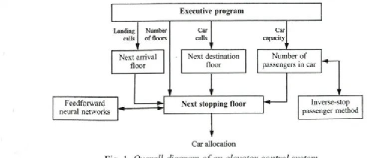
The q u a lity o f se rv ice in m u lti-sto res building is indicated by the average passenger waiting time. Thus, the aim o f this study is reduce the average waiting time for the different traffic pattern. For this reason, it is proposed that neural netw orks learn the likely destinations from one floor to another and then use this information to allocate cares to calls and have been employed to predict elevator demand on a day-to-day basis. This study is an exploration in possibilities o f the various fields in which neural networks can be applied in elevator control. Feedforw ard neural netw orks em bedded in the car control and call distribution module is shown in Figure 1.
Neural network embedded elevator control module is situated in the simulation program and allocates the both landing and car calls to suitable car according to the control algorithm. Inverse-Stop Passenger method was proposed by A l-Sharif [12]. This m odule can continuously learn passenger arrival rate patterns throughout the day o f the elevator system, and predict the passenger arrival rates for each floor and destination in the building. In an elevator system , w hen a landing call is registered at a given floor, the information the group control system receives is the floor identification and desired direction o f travel. The next stopping flo o r as the d e s tin a tio n is n o t know n. The information could be used by the elevator control algorithm to send the best car to answer the landing
call. Conservative approaches can not provide such flexibility and autonomous behavior. As a preferred embodiment o f this technique, population behavior is m odeled using neural netw ork approach as described by R um elhart and M cClelland [13]. A rtific ia l n e u ra l n e tw o rk a p p lic a tio n in identification o f vertical traffic pattern uses a feedforward neural network to perform this task [14]. Another neural network application in elevator control intends to be a new method using artificial neural networks to predict the response time o f an elevator to a landing call.
2.1 The Structure of Artificial Neural Networks
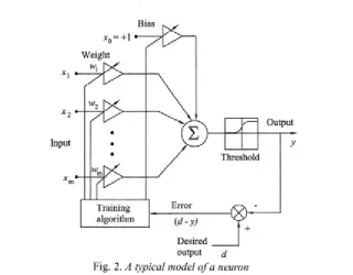
Artificial neural networks consists several units that carry out a simple task and are fully interconnected. This layout allows reproducing some features of the brain that are not usual on computers [15], A typical simulation o f the action o f a single neuron is shown in Figure 2. The strength o f each synaptic junction is represented by a weight, with a positive sign for excitatory connections, and negative o th erw ise. T he o u tp u t o f a n euron is easily computed by using vector multiplication o f the input and weights, and adding the trainable bias to each neuron for speeding up convergence. A bias is included in the neurons to allow the activation functions to be offset from zero. This feature can be easily incorporated by adding an additional w eig h t connected to +1, to each neuron. The a d d itio n a l b ia s term also d e term in es the spontaneous activity o f the neuron. This can also be achieved as setting the threshold values for the sudden onset o f a high firing rate, hence the term non-linear threshold element.
Car allocation
Input
output cl
Fig. 2. A typical model o f a neuron
A fte r an in p u t has b e e n a p p lie d as a stim ulus, it is propagated through each unit on output is generated. This output is then compared the desired output, and an error signal is computed for each output. The net input vector a to neuron j
is a n o n -lin ear function o f the inputs x o f the neurons that are connected to j and the weights w..
on these conditions is: m
aj = i * j (i).
1=1
Using sigmoid non-linearity at each node, the neuron has a real-valued output y that is a nonlinear function o f the net input is:
1
y j ~ j + e-a(°j-ej) (2)’
w here 0 it the threshold value for the artificial
J
n eu ro n s. Im p ro v in g the p e rfo rm an ce sigm oid tem perature a is used and slightly higher than one w h ich m akes the m iddle p o rtio n o f the curve com paratively flatter. The node characteristics o f an artificial neuron are thus determined by Equation (
2
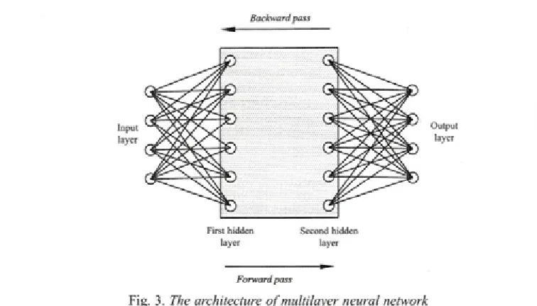
).The presented system can be adapted to do this purpose because o f all the input values such as num ber o f floors are defined as parametrically. A typical m ultilayer neural network used consists o f input and output layers are configured by number o f floors and two hidden layers as depicted in Figure 3. An increase the num ber o f hidden layers
m ay improve generalization capacity. In the present case, after a few trials with the network with one hid d en layer, good convergence could n o t be achieved. The netw ork used, therefore, has two hidden layers as this guarantees it can leam any pattem. There are also no formulae to determine the number o f neurons to arrange in hidden layers. T he m o st u sed p ro c e d u re is to try se v e ra l configurations. To improve the generalization, the num ber o f nodes in hidden layers are double that o f the number o f input layer nodes [16] and [17]. The developm ent o f successful neural netw orks requires considerable time and effort.
In fully connected neural netw orks, the inputs o f the network gets in are: num ber o f car calls, num ber o f up landing calls, num ber o f down landing calls and car directions. The hidden layers are com putational layers and fully connected to input layer. There are no direct connections between the input and output layers. Case information flows forward from the input layer to the output layer through the hidden layers. Each layer consists o f processing element called neurons [18].
Backward pass
Input layer
First hidden layer
Second hidden layer
Output layer
Forward pass
Fig. 3. The architecture o f multilayer neural network
2 .2 The Backpropagation Algorithm
Feedforward neural networks in this study use the backpropagation algorithm, as it is widely u sed and very popular. It provides predictive information and a systematic method for training multilayer neural networks that has been applied to the control o f elevator call allocation [1] and [19]. It does not have feedback connections, but errors are backpropagated during training. Thus, data are processed from the input to output layer, whereas knowledge is performed by the algorithm o f m in im izin g the square erro r by b ackw ard movement [20] and [21].
B a ck p ro p ag atio n neural n etw o rk is an exampled o f supervised learning and applicable for the m ultilayer neural netw ork for it considers weight parameter in all layers. There are two layers o f neural cells between input layer and output layer as shown in Figure 3. The Sigmoid non-linear nodal function is used when the backpropagation learning algorithm is used to train the feedforward network w hich is intended for the next stopping floor prediction.
The backpropagation algorithm is also based on the generalized delta rule which calculates the gradient to find the deepest descent direction, searching for a minimum in the error surface. It calculates first the error in the output layer, then evaluating the contribution o f each hidden neuron in that error. Thus, the corresponding weights are modified in order to reduce the mean squared error between the actual network output and the desired
one. The le arn in g alg o rith m is an iterativ e algorithm , intending to reduce the error at the output. The sequence o f steps involved is as follows.
Step 1 : Initialize all o f the weights to small random values. This breaks the network symmetry and ensures that the netw ork does not become saturated by large values o f weights.
Step 2: Apply an input vector to the input layer and specify the desired network outputs. The inputs can be new on each trial or samples from a train in g set can be presented cyclically until weights stabilize.
Step 3: Calculate the network outputs by performing a forward through the layers, using Eqs. (1) and (2) to calculate the outputs o f individual neurons. The outputs o f the input layer neurons are made equal to the corresponding component of the input vector.
Step 4: Adjust the weights o f the network in a way that minimizes the error using recursive algorithm at the output nodes by:
W-. (t + 1 ) = Wy (?) + g y j E j + e AWj (t +1) (3),
where w is the weight from i-th node to y-th node,
g is a learning rate which is normally sets less than 1 to prevent to oscillation o f weight values, e is a m om entum coefficient and is norm ally set to around 0.9 and where:
and E is the error aty'-th node:
Ej = - y j ( x~ y j ) ( y j - dj ) (5)>
for an output layer, and:
E, = - y J{ i - y J) J J EkwJk (6)>
i
for an intermediate layer neuron.
Step 5: Repeat by going to Step 2.
The major disadvantages o f this algorithm are its slow convergence, the possibility o f being stuck at a local minimum instead o f a global and the memorization instead o f generalization. Various m e th o d s h av e b e e n s u g g e s te d to sp e e d up c o n v e rg e n c e tim e. Two o f th ese in v o lv e the inclusion o f a momentum term and a learning rate term in the weight adjustment equations. Using this m ethod, the network tends to follow the bottom o f narro w gullies in the error surface rather than oscillating from side to side.
There are also problems if the number o f training pattem is small because this patterns using a big network in order to avoid the over fitting o f the training data. Some modifications to the original alg o rith m tend to overcom e these difficulties. Increasing the number o f hidden layers can also im prove the generalized capacity.
2.3 Modification Parameters
M odification parameters can be made to the backpropagation algorithm which may improve its
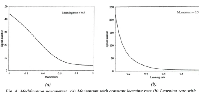
performance and scale the adjustments to weights. T hey in v o lv e change stop the w eig h t u pdate procedure, a variation to improve computational p o w e r an d an e x p lic it sta te m e n t o f the backpropagation algorithm for two hidden layers. A simple change to training law that sometimes results in m uch faster training is the addition o f a momentum term. It is an attempt to try to keep the weight change in process and maintains the same direction the w eight variation, ensuring stability in the learning. F or constant learning rate, the number o f epochs with respect to momentum can be seen in Figure 4. A momentum term is added to speed up the learning stage and takes value o f 0.9 in this study.
L e arn in g ra te as a n o th e r m o d ific a tio n param eter can be used to control the amount which weights are changed during the training and be used as one o f convergence. This convergence is drawn acco rd in g to epoch w ith co n stan t m om entum param eter as shown in Figure 4. Therefore, the learning rate is set at 0.5 for training the network. As can be seen from Figure 4, care has to be taken in choosing the learning rate and the momentum, in order to ensure convergence. Higher learning rate values make convergence faster, but learning rate values higher than 0.5 must be avoided, as well as momentum values higher than 0.9.
2.4 Training the Network
The process o f learning is known as training. There are th re e p h a se s o f tra in in g . In firs t p h a se ,
(a) (b)
Table 1. Parameters o f neural networks training
Number o f floors n
Number o f layers 4 Neural model backpropagation
Input layer 3n + 3 Topology Feedforward
Number o f neurons 1st Hidden 2 (3 « + 3) Supervision Supervised
2nd Hidden 2 (3 « + 3) Learning mie Generalized delta mie
Output layer n I/O information Binary
Input layer Linear Momentum 0.9
Transfer function 1st Hidden Sigmoid Learning rate 0.5
2nd Hidden Output layer
Sigmoid Linear
Sigmoid temperature 0.5
supervised learning is used to train the network to predict the next stopping floor. The training set is first presented to the network, until it learns the internal representation o f training pairs and then the error at the output node is reduces along the steepest descent direction. The initial weights and the th resh o ld s are random ly g en erated at the beginning. At the end o f the first phase o f training, weights from the input layer to the hidden layer o f the network are fixed. In phase two, the output layer o f the network is retrained to emulate the existing controller. In phase three, single weights in the output layer o f the network are perturbed, and the resulting performance is measured. The weights are th e n m o d ifie d in th e d ire c tio n o f im p ro v e d p e rfo rm an ce. N eu ral n etw o rk s to be tra in e d wherein the parameters specified in Table 1 were employed.
Because o f the size o f the training pattem, it is kept a separate file produced by the training pattern program . A training pattem consists o f training pairs o f inputs and outputs. The inputs are
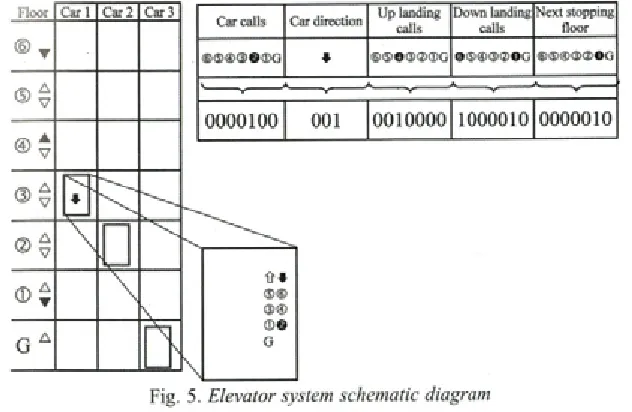
car calls, up and landing calls and car direction. All the inputs were introduced for several epochs. The ou tp u ts are the next sto p p in g floors. A schematic diagram o f an elevator system o f a group of cars is illustrated in Figure 5. A group o f cars has to handle a group o f passengers in a building with a given number o f floors. In this figure, the elevator cars are represented as boxes in the diagram. In addition, a black circle indicates a car call, a b lack triangle indicates a landing call assigned to an elevator, and a w hite triangle indicates an unassigned landing calls.
W hen considering even small number of stops, the size o f the training pattern becomes extremely large to be calculated manually. Thus it decodes the direction and the position linearly, and the calls in binary [12]. The module is used to classify the input vectors and to convert them in binary inform ation as shown in Figure 5, by a processing module active code/binary code. Thus, the neural network receives only binary data that represent a favorable situation for applications in
Car calls Car direction U p landing calls
Down landing calls
N ext stopping floor
® ® @ ® © © G * © ® © ® @ ® G ©®@®<2>OG ® ® ® ® ® O G
V
0 0 0 0 1 0 0 0 0 1 0 0 1 0 0 0 0 1 0 0 0 0 1 0 0 0 0 0 0 1 0
large systems. This represents a reduction on the c o m p u ta tio n a l effort necessary to rea liz e the training and an improvement on the quality o f the a n a ly s is . T his form p erm its to re p re s e n t the co ntingences by a binary code and reduce the quantity that is an adequate way o f providing a faster training and the analysis m ore reliable [9] and [12].
In order to train the neural network to be able to calculate the next stopping floors, the set o f possible patterns has to be evaluated in advance, and stored in a file to be used later by the training program. While calculating the situations, it finds the n ex t stopping floor corresponding to each simulation, and then writes all these variables to a file. In the sample file record given is Fig. 5, “0” represents no call and “ 1” represents a call to be registered. The length o f record lines depends on the num ber o f floors. The first 7 digits represent the car calls, the next 3 represents the direction (001 for down and 100 for up), the next 7 represents the up landing calls (each digit represents one call), and the next 7 represents the down landing calls and the last 7 digits represents the calculated next sto p p in g flo o rs. T his fo rm at is u se d to give flexibility in order to changing the num ber o f floors during input stage.
Each training pattem was random ly selected to be fed into the network, continuing until all the patterns were done with. This constitutes one epoch o f learning. The netw ork w as trained for 1000 epochs, until the mean squared error dipped below 0.01 th en the p ro g ram sto p s [9]. A fte r 1000 iterations the minimum reached which corresponds to the model that minimizes the fit for the validation data. Further iterations give an increasing criterion and the model becomes worse. Once the training stag e is su ccessfu lly fin ish ed and the trained netw ork is tested, the network is em ployed in the p r e d ic tio n o f th e n e x t s to p p in g flo o rs by c o n s id e rin g w h at has b e e n le a rn t in n o rm al operation mode.
2.5 Overtraining the Network
In neural networks, one o f the m ajor pitfalls is overtraining, analogous to curve fitting for m ie based trading systems. Overtraining refers to the reduction in generalization ability that can occur as networks are trained, and m ay be avoided by early stopping the training stage in time, before an
adaptation to the noise starts. It is difficult to detect an optional stopping moment without the use o f a test set, pruning, reducing the size o f a network after it is trained [12], [15] and [17].
Overtraining occurs when a network has learned not only the basic mapping associated with input and output data, but also the subtile nuances and even the error specific to the training set. Overtraining can be detected during the training stage by the use o f a test set. Once the data set has been selected, it is separated into training and testing subsets. In the testing mode, the network is fed new inputs and utilizes the representation it had previously learned to generate associated outputs without changing its weights.
O vertraining is reduced by lim iting the n u m b e r o f n e u ro n to m in im u m n e c e ssa ry , in creasin g the tra in in g set size, using cro ss- validation training to identify and stop training before over fitting occurs. The cross-validation set was used to monitor generalization during training.
3 THE ELEVATOR CONTROL SIMULATION
In th is s e c tio n th e e le v a to r c o n tro l simulation example is considered. A widely used method for elevator system performance prediction is the use o f simulation. This can usually produce a set o f curves, which describe the behavior o f a certain variable ag ain st the change in system loading. One o f the most useful curves w hich are used to study elevator system performance is the average w aitin g tim e curve v ersu s in te rflo o r demand. Interfloor demand as percentage can be found by dividing the passenger arrival rate by the handling capacity o f the system [2], Simulations are run for several levels o f interfloor demand for the improved control system. At the end o f each simulation, the average waiting time is recorded and the performance figure calculated by dividing th e a v e ra g e w a itin g tim e b y th e in te rv a l to normalize it.
3.1 The Structure of Software
betw een modules and databases. Conversational program m ing techniques have been used to take advantage o f an interactive digital computer. All inputs are checked for validity and where an error is detected the user is prompted as to the correct reply. The principal features o f the simulator are that it can simulate up to 3 cars and 10 floors.
T he lift c o n fig u ra tio n m o d u le is an interactive conversational program which allows the setting up o f all the data defining the system to be sim ulated. Three cars w ith various contract capacities are used to service the whole building. In this program interfloor distance, contract speed, time for opening and closing the door, passenger transfer time are chosen by users. After that the training module is executed to be able to calculate the next stopping floors, the set o f possible patterns has to be evaluated in advance, and stored in a file to be used in neural netw orks m odule. In this program, feedforward neural network is used to allocate the calls to the best cars during day period by means o f weight matrix. The software uses the backpropagation learning algorithm to training the network.
Fig. 6. The flow chart o f simulation program
The traffic analysis and control module w hich is em bedded in the sim ulation program assigns the landing calls to the convenient cars. This module decides which car to be dispatched to which floor. In the traffic analysis and control module, the executive is the simplest part in the module and is used to control which sub-module is to mn. After each sub-module has been used, the executive is re -e n te re d to d e te rm in e the next phase in a simulation. The executive also controls the access to the traffic an aly sis and control m odule. It generates landing and car calls. The car capacity is selected by users. The goal o f the module is to obtain the next stopping floor, which is important in the allocation o f the cars. In the first step, the landing calls and car calls, next arrival floors and next destination floors are determined. The number o f passengers in the car, which one o f the factors in selecting the next arrival floor is determined by m eans o f Inverse-Stop Passenger method [12]. A fter two steps the next stopping floors can be determined using feedforward neural networks.
The output o f simulation is the distribution o f calls to the most suitable cars and car direction. The results are kept a separate file and saved in a file to be used later by the training program. Performance calculations have been arranged to present graphs to the user. They include round trip time, average w aiting tim e and the normalized system performance figure which are used for a p e rfo rm a n c e co m p ariso n o f elev ato r control systems.
The flow chart o f simulation program which employs both conventional Duplex/Triplex control and the neural network algorithm is depicted in Figure 6 [9],
3.2 Performance Criteria and Calculations
The performance objectives o f an elevator system can be defined in many ways. One possible objective is to minimize the average waiting time, which is the time between a passenger’s arrival and entry into a car. The passenger waiting time would be the fiest indicator o f the quality o f service that an installed elevator system could provide. To calculate the average waiting time according to car loads, one can find:
CC
(7 ),
w here P is the num ber o f passengers enter the car at the m ain terminal, CC is the contract or rated capacity o f car, H is the highest reversal floor, S is the expected num ber o f stops, tv is the single floor transit tim e, ts is stopping time and t passenger transfer tim e and L is the number of cars within a elevator group. The highest reversal floor and the expected num ber o f stops are determined by means o f sim ulation program. The number o f passengers in the car is calculated by means o f Inverse-Stop Passenger method.
The normalized system performance figure is d e fin e d as the p ercentage o f the sim ulated a v e ra g e p a s s e n g e r w a itin g tim e d iv id e d by calculated up-peak interval. The interfloor demand is defined as the interfloor arrival rate divided by calculated up peak handling capacity.
4 SIMULATION RESULTS
To investigate the im provem ent obtained by using the group control where neural network are em bedded into the D uplex/T riplex control algorithm , sim ulations are run for several levels o f interfloor traffic dem and level for the improved D u p le x /T r ip le x c o n tro l s y s te m (IC S ). T he sim u latio n program is executed for a building w hich population 1000 w ith 10 floors, three cars w ith contract capacity equal to each is used to service the whole building. Interfloor distance is fix e d at 3.3 m, co n tract speed 1.0 m /s. D oor operating time is 20 seconds while closing time 2.6 secs and passenger transfer tim e is 1.2 secs. S im ulations output file keeps the record o f the ro u n d trip tim e, the in terv al and the average passenger w aiting time. The program runs on a 4 8 6 P C w ith 8 M B R A M , 2 5 6 M B h ard d isk c o n fig u ra tio n . T he n o rm a liz e d p e rfo rm a n c e
figures, w ith respect to the interfloor demand are com pared w ith other traffic control algorithm s which are the fixed sectoring priority timed system (FSPTS) and the fixed sectoring common sector sy s te m (F S C S S ) c o n tro l a lg o rith m . F o r a p e rfo rm an ce co m p ariso n , the resu lts o f each sim ulation perform ed under the same conditions have been tabled. Table 2 gives the comparison o f the perform ance figure o f the traffic control algorithms in a norm alized form. Existing control algorithms as standards are used for com parison [9] and [10].
The simulation results showed the proposed method could provide a considerable improvement o f the call assignment, if the method is implemented to an elevator control system for low-rise buildings in up peak traffic conditions. The ICS shows an improvement over the fixed sectoring priority timed system (FSPTS) and the fixed sectoring common sector system (FSCSS) control algorithm, when the interfloor demand exceeds 55%.
5 EXPANSIONS IN MATERIALS HANDLING SYSTEMS
Automated Guided Vehicle (AGV), one o f the materials handling systems, is widely used in fle x ib le m a n u fa c tu rin g sy ste m s. D u e to the in c re a s in g c o m p le x ity o f m a n u fa c tu rin g environments coupled with the need for increased fle x ib ility in A G V sy stem s. The d e sig n and evaluation o f AGV systems are highly complex because o f the randomness and the large number o f variables involved. T ypically the desig n o f m aterial handling systems using AG Vs includes determination o f the vehicle guidepath layout, the traffic flow pattern, the number o f vehicles required [
22
],Table 2. Comparison o f the system performance
Interfloor demand Performance figure [%]
[%] FSPTS FSCSS ICS
10 25.7 28.5 42.5
20 31.4 37.1 51.3
30 45.6 51.3 64.1
40 64.6 66.9 78.8
50 86.6 82.8 93.1
60 114.0 106.8 112.4
70 143.9 133.4 134.1
80 174.9 163.8 151.6
90 209.5 195.2 168.2
The problem o f AGV consists o f the operational control strategies o f dispatching and routing o f a set o f AG Vs and can be solved by using a lot of heuristic algorithms as Petri nets, fuzzy logic and neural networks. Hao and Lai [23] have described a neural network approach for the AGV problem and proposed neural network models to perform dispatching and routing tasks for the AGV under conditions o f single or multiple vehicles which are based on Kohonen’s self-organizing feature maps. B ostel et.al. have proposed a new navigation technique for A G V ’s based on neural networks [24],
The desired path along which the vehicle should move may be a fixed route, semi fixed route or an arbitrary route. Fixed route im plies the installation o f a fixed active guide like an energized cable or a passive one like a reflecting strip painted on the p la n t flo o r, ft is e s s e n tia lly A G V p ro g ram m ed to convey m aterials or w ork in progress through a predefined route in horizontal environm ent. It is sim ilar w ith elevator w hich c a rrie s th e p a s s e n g e rs and lo ad s th ro u g h a predefined route in vertical environment.
Vehicle travel time o f AGV is a fundamental p a ra m e te r fo r so lv in g v a rio u s fle x ib le m an u fa c tu rin g system d esign p ro b lem s. The feedforw ard neural netw orks em bedded system presented in this paper possesses generality for transportation systems. It is mostly used in elevator engineering, but it could be used for single vehicle or multi vehicle A G V ’s control up to 3 vehicles in flexible manufacturing systems, if it is adapted and generalized for fixed route path problem using average w aiting tim e and average travel tim e concepts as described in elevator traffic calculation. This control system could be applied the static production environment where the product mix or machine routings are assumed to be stable over time. It can also be used to determine and estimate the vehicle waiting times o f AGV. It is believed that the models can be applied to a number o f call- a-ride cases, such as AGV travel.
6 CONCLUSIONS
In this p ap er the ou tlin e o f a program preparing feedforward neural networks has been introduced. It has been seen that the average waiting tim e w hich defines elevator perform ance goes down satisfactorily thanks to the neural network applied to elevator control systems and that it gives
better results compared to conventional methods. It could effectively support the conventional group control system and shorten the average waiting time by fo re c a s tin g car p o sitio n and u sin g call distribution laws. The system results are shown in T able 2 co m p a re d to th o se o b ta in e d from conventional control algorithm s. A 15 to 20% improvement in performance has been achieved by using this technique. It can be concluded that better results are reached w hen neural netw orks are combined w ith conventional techniques. On the other hand, the main drawback of the method is that it m ainly applies to up-peak traffic. More research is also needed for down-peak, as it depends on building occupancy. This control system may be expanded to the other materials handling systems such as A G V ’s co n tro l p ro b lem w ith a few necessary arrangements.
Acknowledgement
The constructive comments o f the referees are gratefully acknowledged.
7 REFERENCES
[1] M ira v e te , A. New m aterials and new technologies applied to elevators. New York: Elevator World Inc, 2002.
[2] B arney, G.C. Elevator traffic handbook.
London: Spon Press, 2003.
[3] H o, M ., R o b ertso n , B. E le v a to r group su p e rv is o ry co n tro l u sin g fu zzy logic.
Canadian Conference on E levator and Computer Engineering 2, 11.4.4., 1994. [4] Prow se, R.W., Thom son, T., H ow ells, D.
Design and control o f lift systems using expert system s and traffic sensing. E le v a to r technology 4 (Ed. G .C .B arney). London: IAEE Publ, 1992, p.219-226.
[5] Q un, Z., D ing, S., Yu, C., X iaofeng, L. Elevator group control system modeling based on object oriented Petri net. Elevator World,
49(2001)8, p. 9 9 - 105.
[6] Chan, W.L., So, A.T.P. Dynamic zoning for intelligent supervisory control. Int. to Elevator Engineering, 1(1996), p. 1 - 1 0 .
[7] Siikonen, M-L. On traffic planning methodology.
Elevator technology 10 (Ed. A. Lusting). London:
[8] Closs, G.D. The computer control o f passenger traffic in large lift system s. PhD T hesis, University o f Manchester, Institute o f Science and Technology, Manchester, UK, 1970. [9] Im rak , C.E. Traffic analysis, design and
simulation o f elevator systems. PhD Thesis, Is ta n b u l T ech n ical U n iv e rsity , Ista n b u l, Turkey, 1996.
[10] Im rak, C .E., Barney, G.C. Application o f neural networks on traffic control. Elevator technology 9 (Ed. G.C.Bamey), IAEE Publ, London, 1998, p. 140-148.
[11] Imrak, C.E., Ozkirim, M. The modeling and sim ulation o f elevator group control systems for public service buildings. Preprints the 3rd IFAC Workshop DECOM-TT 2003, Istanbul, Turkey, June 2003, p. 159-164.
[12] A l-S harif, L.R. Predictive methods in lift traffic analysis. PhD Thesis, U niversity o f M a n c h e s te r In s titu te o f S c ie n c e and Technology, Manchester, UK, 1992.
[13] Rum elhart, D.E., M cClelland, J.L. Parallel d istrib u te d p ro cessin g . Vol. 1 and 2, Cambridge: MIT Pres, 1986.
[14] So, A.T.P., Beebe, J.R., Chan, W.L., Liu, S.K.
E le v a to r tra ffic p a ttern recognition by artificial neural network. Elevator technology 6 (Ed. G .C .B arney). London: IA EE Publ, 1995, p. 122-131.
[15] M ukherjee, A., Deshpande, J.M. Application o f artificial neural netw orks in structural d e sig n e x p e rt sy ste m s. C om puter & Structures, 54(1995)3, p. 367-375.
[16] K om , A.G. Neural networks and fuzzy-logic co n tro l on p e rso n a l co m puters and workstations. London: MIT Press, 1995.
[17] Lisboa, R .G . N eural netw ork current application. N ew York: Chapman and Hall Pub, 1992.
[18] A le x a n d ris , N ., C h ris s ik o p o u lo s , V., Vassilacopoulos, G. Lift - an expert system fo r lift system design. Elevator technology 2 (Ed. G.C.Bamey). London: IAEE Publ, 1988, p. 1-9.
[19] Rumelhart, D.E., Hinton, G.E., Williams, R.J. Learning representations by backpropagation errors. Nature, 323 (1986), p. 533-536. [20] Jovanovič, J., Krivokapič, Z. The application
o f an a ty p ic a l n e u ra l n e tw o rk s w h en quantifying the m odeling o f environmental a sp e c ts. S tro jn iški vestn ik - Jo u rn a l o f Mechanical Engineering, 52(2006)6, p. 392- 403.
[21] Krivokapič, Z., Zogovic, V., Spaic, O. Using neural networks to follow the wear o f a S390 tw ist drill. Strojniški vestnik - Journal o f M echanical Engineering, 52(2006)7-8, p. 437-442.
[22] Koo, P-H., Jang, J. Vehicle travel time models for AGV systems under various dispatching rules. The International Journal o f Flexible Manufacturing Systems, 14(2002), p. 249-261. [23] Hao, G., Lai, K.K. Solving the AGV problem
via a self-organizing neural netw ork. The Journal o f the Operational Research Society,
47(1996), p. 1477-1493.
![Figure 6 [9],](https://thumb-us.123doks.com/thumbv2/123dok_us/8954036.1863404/9.482.36.422.335.668/figure.webp)
