5
Copyright © 2018. IJEMR. All Rights Reserved.
Volume-8, Issue-1 February 2018
International Journal of Engineering and Management Research
Page Number: 5-13
Structural Analysis and Optimization of Nozzle Attachment on Channel
Shell Design
M. Sailaja1 and Dr. N.V.N Indra Kiran2
1Assistant Professor, Department of Mechanical Engineering, Anil Neerukonda Institute of Technology & Sciences,
Visakhapatnam, INDIA
2
Professor, Department of Mechanical Engineering, Anil Neerukonda Institute of Technology & Sciences, Visakhapatnam, INDIA
1
Corresponding Author: [email protected]
ABSTRACT
In Channel shells, Nozzles are required for inlet and outlet purposes either to carry fluids or for providing multipurpose connections. If these nozzles present on peak of the dish end do not disturb the symmetry of the shell. However sometimes process requires that nozzles to be placed on the periphery of the shell. These nozzles disturb the symmetry of the shell. Geometrical parameters of nozzle connections may significantly vary even in one channel shell. These nozzles cause geometric discontinuity of the shell wall. So a stress concentration is created at the junction. Hence a detailed analysis is required. If nozzles are placed on the periphery of a channel shell, they disturb the axis symmetry of the system and cause eccentricity. Sometimes this cause generation of a couple & lead to a structural imbalance. So that it need to analysed in FEA to understand effects of nozzle on Stress attributes of the shell. This work also studies the effect of eccentricity of the nozzles under varying thickness of shell and reinforcement pad. The effect of material concession for nozzle and Shell on the stress induced is also studied. From the results obtained by ANSYS, optimum study was performed by response surface methodology to obtain optimum shell thickness and reinforcement pad thickness for different class of materials.
Keywords-- Channel shell, Nozzles, FEA, ANSYS,
Optimization
I.
INTRODUCTION
Geometrical parameters of nozzle connections may significantly vary even in one pressure vessel. These nozzles cause geometric discontinuity of the vessel wall. So a stress concentration is created around the opening [1-4]. The junction may fail due to these high stresses. Hence a detailed analysis is required. One of the parts of overall structural analysis for nozzle
connections is the stress analysis of two intersecting shells.
Due to different loadings applied to these structures, a local stress state of nozzle connection characterized by high stress concentration occurs in intersection region. Internal pressure is primary loading used in the structure analysis for determination of main vessel-nozzle connections. However the effect of external forces and moments applied to nozzle should be taken into consideration in addition to the stresses caused by the internal pressure. External loading usually are imposed by a piping system attached to the nozzle [5-7]. Values of the loads & moments are calculated by an analysis of piping system.
Many works including analytical, experimental & numerical investigations have been devoted to the stress analysis of nozzle connections in pressure vessels, subjected to different external loadings. The codes suggest a procedure to design the junction, but do not provide any methodology to calculate the extended and magnitude of these high stresses. The available analytical solution WRC-107 is limited to simple geometries [8-10]. So, there is need to carry out a detailed finite element analysis of the junction to calculate stresses at the junction & both in the vessel & in the nozzle [11-14]. ANSYS package is used as a finite element tool.
II.
DESIGN OF NOZZLES
2.1 Problem Statement
6
Copyright © 2018. IJEMR. All Rights Reserved.
also studies the effect of eccentricity of the nozzles under varying thickness of shell and reinforcement pad. The effect of material concession for nozzle and Shell on the stress induced is also studied. From the results obtained by ANSYS, optimum study was performed by response surface methodology to obtain optimum shell thickness and reinforcement pad thickness for different class of materials.
2.2 Shell thickness calculation for Carbon Steel material:
s
P * R
t
S* E 0.6P
as per UG-27 (C)(1)Where P is internal design pressure R is inside radius of the shell S is maximum allowable stress E is joint efficiency
ts is minimum required thickness of shell
P = 12.3 kgf/cm2 R = 228 mm S = 1202.25 kgf/cm2 E = 0.85
Therefore, by substituting the above values in the given formula we get
ts = 2.7648 mm
Actual thickness ts= 2.7648 + corrosion allowance =
2.7648 + 3 = 5.7648 mm
2.3 Shell thickness calculation for Stainless Steel material:
s
P * R
t
S* E 0.6P
as per UG-27 (C)(1)S = 1264.44 kgf/cm2
Therefore, by substituting the above values in the given formula we get
ts = 2.627 mm (There is no corrosion allowance)
2.4 Shell thickness calculation for Alloy Steel material:
s
P * R
t
S* E 0.6P
as per UG-27 (C)(1)S = 1070.70kgf/cm2
Therefore, by substituting the above values in the given formula we get
ts = 3.1066 mm
Actual thickness ts= 3.1066 + corrosion allowance =
3.1066 + 3 = 6.1066 mm
Maximum allowable working pressure at given thickness t = 7 mm
As per TEMA minimum thickness of the shell t = 10 mm
t = actual thickness – corrosion allowance = 10 – 3 = 7 mm
2.5 Nozzle thickness calculation for D2 and V2:
ASME code, Section-VIII, Div. 1, 2015, UG-37 to UG-45
Actual outside diameter used in calculation = 60.325 mm Actual thickness used in calculation = 8.738 mm
Required thickness per UG-37(a) of cylindrical shell,
s
P * R
t
S* E 0.6P
= 2.347 mmRequired thickness per UG-37(a) of Nozzle wall,
n
P * R
t
S* E 0.4P
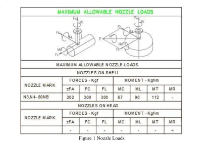
= 0.3073 mmThe maximum allowable Nozzle loads were shown in figure 1 below.
7
Copyright © 2018. IJEMR. All Rights Reserved.
III.
MODELING OF CHANNEL
SHELL
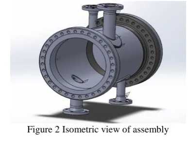
The parts of Channel shell attached with Nozzles, vent and drain were modelled in the SOLIDWORKS software with the help of drawings
provided. The parts were also assembled in
SOLIDWORKS software.
Figure 2 Isometric view of assembly
IV.
ANALYSIS ON CHANNEL SHELL
AND NOZZLES
A static analysis calculates the effects of steady loading conditions on a structure, while ignoring inertia and damping effects, such as those caused by time-varying loads. A static analysis can, however, include steady inertia loads, and time-varying loads that can be approximated as static equivalent loads. Structural analysis is probably the most common application of the finite element method as it implies bridges and buildings, naval, aeronautical, and mechanical structures such as ship hulls, aircraft bodies, and machine housings, as well as mechanical components such as pistons, machine parts, and tools. Linear static analysis is concerned with the behavior of elastic continua under prescribed boundary conditions and statically applied loads. The applied loads in this case are maximum allowable Nozzle loads. The FE analysis is carried out using ANSYS.
Carbon steel material with Shell thickness of 10 mm and RF pad thickness of 10 mm is shown in figure 3 to figure 5.
Figure 3 Stress for 80 mm and Carbon steel material
Figure 4 Strain for 80 mm and Carbon steel material
Figure 5 Deformation for 80 mm and Carbon steel material
Nozzle to channel shell centre distance of 80 mm and Carbon steel material shown in Table 1
Table 1: Nozzle to channel shell centre distance of 80 mm and Carbon steel material
SHELL THICKNESS
(mm)
RF PAD THICKNESS
(mm)
STRESS (MPa)
DEFORMATION (mm)
STRAIN
10 10 83.017 0.18011 0.00042583
10 12 82.99 0.16482 0.00042573
8
Copyright © 2018. IJEMR. All Rights Reserved.
Similarly the Stress, strain and deformation values were found on the model by varying the nozzle to channel shell centre distance and their materials.
Nozzle to channel shell centre distance of 80 mm and Stainless steel material is shown in Table 2
Table 2 Nozzle to channel shell centre distance of 80 mm and Stainless steel material
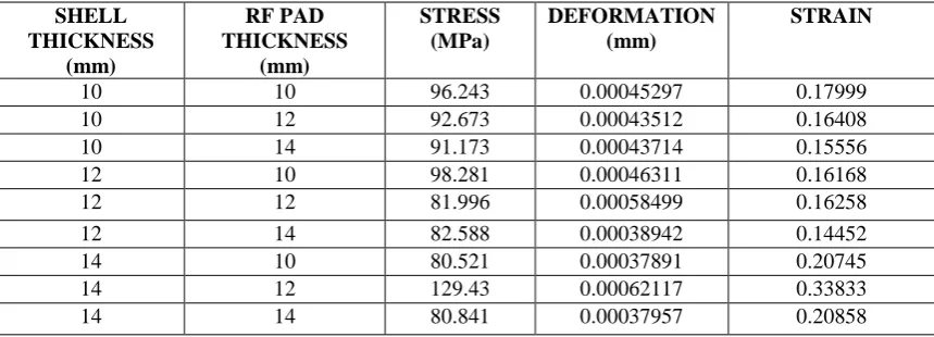
Nozzle to channel shell centre distance of 80 mm and Alloy steel material shown in Table 3
Table 3 Nozzle to channel shell centre distance of 80 mm and Alloy steel material
Nozzle to channel shell centre distance of 100 mm and Carbon steel material is shown in Table 4
12 10 75.38 0.16514 0.00037588
12 12 73.651 0.16582 0.00037779
12 14 71.991 0.14566 0.00035123
14 10 72.851 0.21079 0.00038688
14 12 90.58 0.33264 0.00047315
14 14 73.652 0.212 0.00039113
SHELL THICKNESS
(mm)
RF PAD THICKNESS
(mm)
STRESS (MPa)
DEFORMATION (mm)
STRAIN
10 10 85.515 0.00044312 0.18763
10 12 85.588 0.0004435 0.1722
10 14 87.405 0.00046238 0.16421
12 10 75.461 0.0003913 0.17077
12 12 75.551 0.00039149 0.17173
12 14 74.807 0.00039487 0.15308
14 10 74.453 0.00038678 0.21615
14 12 95.634 0.00054364 0.34898
14 14 74.826 0.00038774 0.21735
SHELL THICKNESS
(mm)
RF PAD THICKNESS
(mm)
STRESS (MPa)
DEFORMATION (mm)
STRAIN
10 10 96.243 0.00045297 0.17999
10 12 92.673 0.00043512 0.16408
10 14 91.173 0.00043714 0.15556
12 10 98.281 0.00046311 0.16168
12 12 81.996 0.00058499 0.16258
12 14 82.588 0.00038942 0.14452
14 10 80.521 0.00037891 0.20745
14 12 129.43 0.00062117 0.33833
9
Copyright © 2018. IJEMR. All Rights Reserved.
Table 4 Nozzle to channel shell centre distance of 100 mm and Carbon steel material
Nozzle to channel shell centre distance of 100 mm and Stainless steel material is shown in Table 5
Table 5 Nozzle to channel shell centre distance of 100 mm and Stainless steel material
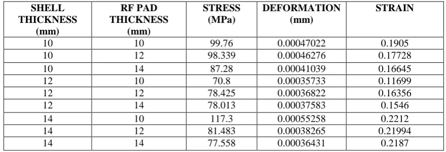
Nozzle to channel shell centre distance of 100 mm and Alloy steel material is shown in Table 6.
Table 6 Nozzle to channel shell centre distance of 100 mm and Alloy steel material
Nozzle to channel shell centre distance of 120 mm and Carbon steel material is shown in Table 7
SHELL THICKNESS
(mm)
RF PAD THICKNESS
(mm)
STRESS (MPa)
DEFORMATION (mm)
STRAIN
10 10 80.058 0.0004198 0.19759
10 12 79.817 0.00040935 0.18666
10 14 76.017 0.00038984 0.17343
12 10 76.09 0.00034089 0.12728
12 12 69.033 0.00035405 0.17318
12 14 70.235 0.00034255 0.16119
14 10 71.051 0.00037085 0.23011
14 12 82.552 0.0004315 0.22819
14 14 78.149 0.00041338 0.22702
SHELL THICKNESS
(mm)
RF PAD THICKNESS
(mm)
STRESS (MPa)
DEFORMATION (mm)
STRAIN
10 10 84.303 0.00047022 0.1905
10 12 82.814 0.00042916 0.1808
10 14 81.087 0.00042015 0.1752
12 10 70.187 0.00036378 0.12111
12 12 72.152 0.00038654 0.17236
12 14 73.629 0.00039947 0.16407
14 10 75.364 0.00039088 0.23063
14 12 75.323 0.00039039 0.22941
14 14 73.806 0.00003987 0.2282
SHELL THICKNESS
(mm)
RF PAD THICKNESS
(mm)
STRESS (MPa)
DEFORMATION (mm)
STRAIN
10 10 99.76 0.00047022 0.1905
10 12 98.339 0.00046276 0.17728
10 14 87.28 0.00041039 0.16645
12 10 70.8 0.00035733 0.11699
12 12 78.425 0.00036822 0.16356
12 14 78.013 0.00037583 0.1546
14 10 117.3 0.00055258 0.2212
14 12 81.483 0.00038265 0.21994
10
Copyright © 2018. IJEMR. All Rights Reserved.
Table 7 Nozzle to channel shell centre distance of 120 mm and Carbon steel material.
Nozzle to channel shell centre distance of 120 mm and Stainless steel material is shown in Table 8
Table 8 Nozzle to channel shell centre distance of 120 mm and Stainless steel material
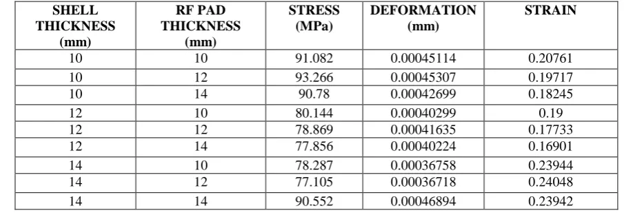
Nozzle to channel shell centre distance of 120 mm and Alloy steel material is shown in Table 9
Table 9 Nozzle to channel shell centre distance of 120 mm and Alloy steel material
V.
OPTIMIZATION BY RESPONSE
SURFACE METHODOLOGY
RSM is an anthology of statistical and mathematical methods, helpful in generating improved methods and optimizing the process. RSM is more
SHELL THICKNESS
(mm)
RF PAD THICKNESS
(mm)
STRESS (MPa)
DEFORMATION (mm)
STRAIN
10 10 79.651 0.00040848 0.21652
10 12 78.953 0.00040502 0.20464
10 14 75.772 0.00038864 0.18903
12 10 74.473 0.00036476 0.19748
12 12 81.802 0.00039231 0.1859
12 14 76.802 0.0003732 0.17558
14 10 84.304 0.0004403 0.2562
14 12 81.69 0.00043423 0.25271
14 14 87.025 0.00045948 0.25113
SHELL THICKNESS
(mm)
RF PAD THICKNESS
(mm)
STRESS (MPa)
DEFORMATION (mm)
STRAIN
10 10 86.408 0.00047972 0.21671
10 12 85.744 0.0004779 0.20402
10 14 86.735 0.00048708 0.19193
12 10 74.948 0.00040321 0.20016
12 12 79.816 0.00041478 0.18768
12 14 76.653 0.00041231 0.17897
14 10 74.479 0.00038596 0.25
14 12 72.999 0.00039276 0.25137
14 14 90.112 0.00051513 0.25034
SHELL THICKNESS
(mm)
RF PAD THICKNESS
(mm)
STRESS (MPa)
DEFORMATION (mm)
STRAIN
10 10 91.082 0.00045114 0.20761
10 12 93.266 0.00045307 0.19717
10 14 90.78 0.00042699 0.18245
12 10 80.144 0.00040299 0.19
12 12 78.869 0.00041635 0.17733
12 14 77.856 0.00040224 0.16901
14 10 78.287 0.00036758 0.23944
14 12 77.105 0.00036718 0.24048
11
Copyright © 2018. IJEMR. All Rights Reserved.
frequently used in analyzing the relationships and the influences of input parameters on the responses. The method was introduced by G. E. P. Box and K. B. Wilson in 1951. RSM uses a set of designed experiments to obtain an optimal response. Box and Wilson used first-degree polynomial model to obtain DOE through RSM and acknowledged that the model is only an approximation and is easy to estimate and apply, even when little information is known about the process.
RSM also improves the analyst’s understanding of the sensitivity between independent and dependent variables. RSM is an experimental strategy and has been
employed by research and development personnel in the industry, with considerable success in a wide variety of situations to obtain solutions for complicated problems.
In response optimization we will get the optimal values of the input parameters Shell thickness and RF Pad thickness, and the output parameters Stress, Strain and Deformation.
Goal of experiment
To maximize the Stress
To maximize the Strain
To maximize the Deformation
Table 10 Defining Goal of experiment for Nozzle to channel shell centre distance of 80 mm and Carbon steel material
Parameters Goal Lower Target Upper
Stress (MPa) Maximum 71.9910 90.5800 90.5800
Strain Maximum 0.0004 0.0005 0.0005
Deformation Maximum 0.1457 0.3326 0.3326
Similarly the goals are defined by varying the nozzle to channel shell centre distance and material of construction.
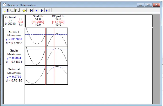
5.1 Optimization Results:
Result for Nozzle to channel shell centre distance of 80 mm and for Carbon steel material is shown in the figure 6.
Figure 6 Response Optimization for Nozzle to channel shell centre distance of 80 mm and Carbon steel material
Response Optimization
Global Solution
Shell thickness (mm) = 14.0000 RF pad thickness (mm) = 11.4150
Predicted Responses
Stress (MPa) = 82.7600, Strain = 0.0004,
Deformation (mm) = 0.2769
Table 11 Predicted responses using RSM
Shell thickness (mm)
RF Pad thickness (mm)
Stress (MPa) Strain Deformation (mm)
14 12 82.76 0.004 0.2769
12
Copyright © 2018. IJEMR. All Rights Reserved.
14 12 105.713 0.001 0.282
14 14 79.2150 0.0004 0.2352
10 14 82.1265 0.0005 0.1846
14 10 107.221 0.001 0.2918
14 14 85.8037 0.0005 0.2498
14 14 86.6461 0.0005 0.2494
14 14 87.3034 0.0004 0.2383
From the results obtained by RSM it is observed that shell thickness of 14 mm and RF Pad thickness of 10 mm take highest stress, strain and deformation values.
VI.
CONCLUSIONS
1. The present thesis deals with Design and
modelling of channel shell attached with Nozzles, vent and drain. The design based on allowable stresses on shell and nozzles, the shell thickness and RF Pad thickness were calculated for different material taken. The modelling of the channel shell and nozzles was done using SOLIDWORKS software.
2. The maximum stress values are obtained from the analysis for all the load cases. From the results of analysis, it can be observed that the maximum stress occurs at the junction of Pressure Vessel and the nozzle. High stress concentration is developed at this location due to abrupt change in the geometry and the consequent change in stress flow.
3. From the results obtained by ANSYS, optimum
study was performed by response surface methodology to obtain optimum shell thickness and reinforcement pad thickness for different class of materials.
4. Based on the results obtained from Response surface methodology in MINITAB it is finally concluded that Alloy steel was the best material in the construction of channel shell and nozzles with nozzle to shell distance of 100 mm and Shell Thickness as 14 mm, RF PAD Thickness as 10 mm
REFERENCES
[1] Pravin Narale & Prof. P. S. Kachare. (2012). Structural analysis of nozzle attachment on pressure vessel design. International Journal of Engineering Research and Application, 2(4), 1353-1358.
[2] Vijayraj G Parmar & D. S. Shah. (2016). Finite element analysis of nozzle for vertical Pressure vessel.
International Journal of Advances in Production and Mechanical Engineering (IJAPME), 2(3), 16-24.
[3] G.S. Jagadale & M.S. Ramgir Nozzle. (2015). Load stress analysis using wrc 107 and wrc 297. International Engineering Research Journal (IERJ), Special Issue 2, 1191-1194.
[4] Ramesh Chandra Panda. (2016). ANSYS-based
stress evaluation in pressure-vessel design. ADR
Journals, 3(3 & 4), 12-21.
[5] V.N. Skopinsky & A.B. Smetankin. (2006). Modelling and stress analysis of nozzle connections in ellipsoidal heads of pressure vessels under external loading. International Journal of Applied Mechanics and Engineering, 11(4), 965-979.
[6] Jerzy Lewiński. (2014). Equivalent stress in a
pressure vessel head with a nozzle. Journal of
Theoretical and Applied Mechanics, 52(4), 1007-1018. [7] Manisha A. Patel. (2015 June). Design and analysis of large opening nozzle as per asme design code and local stresses evaluated at nozzle–shell junction by bulletin wrc-107. International Journal of Advance Engineering and Research Development, 6, 66-77. [8] Usman Tariq Murtaza & Mohammad Javed Hyder. (2015). Design by analysis versus design by formula of a
pwr reactor pressure vessel. Proceedings of the
International Multi Conference of Engineers and Computer Scientists, 2, 18-20.
[9] Navnath V. Avhad & Vijay G. Bhamre. (2015 August). Investigating stress level through fea of nozzles of carbon drain vessel by asme sect-VIII. International Research Journal of Engineering and Technology, 2(5), 918-921.
[10] V. V. Wadkar, S.S. Malgave, D.D. Patil, H.S. Bhore, & P. P. Gavade. (2015 July-Dec). Design and Analysis of Pressure Vessel using Ansys. Journal of Mechanical Engineering and Technology, 3(2), 01-13. [11] A. Hardik B. Nayak & B. R. R. Trivedi. (2011 December). Stress analysis of reactor nozzle to head junction. International Conference in Institute of Technology, Nirma University, Ahmedabad, 1-5.
[12] Andrade, Tatiana Lima, Paula, & Wagner Andrade de. (2015). Analysis of stress in nozzle/shell of cylindrical pressure vessel under internal pressure and external loads in nozzle. Andrade, Tatiana Lima et al. International Journal of Engineering Research and Applications, 5(9), 84-91.
13
Copyright © 2018. IJEMR. All Rights Reserved.
[14] Busuioceanu (Grigorie) Paraschivaa, Stefanescu Mariana-Florentinab, & Ghencea Adrianc. (2016 February). Study of stresses and stress concentrations in