ePublications at Regis University
All Regis University Theses
Fall 2007
Network Access Control: Disruptive Technology?
Craig Fisher
Regis University
Follow this and additional works at:
https://epublications.regis.edu/theses
Part of the
Computer Sciences Commons
This Thesis - Open Access is brought to you for free and open access by ePublications at Regis University. It has been accepted for inclusion in All Regis University Theses by an authorized administrator of ePublications at Regis University. For more information, please [email protected].
Recommended Citation
Fisher, Craig, "Network Access Control: Disruptive Technology?" (2007).All Regis University Theses. 94.
College for Professional Studies Graduate Programs
Final Project/Thesis
Disclaimer
Use of the materials available in the Regis University Thesis Collection
(“Collection”) is limited and restricted to those users who agree to comply with
the following terms of use. Regis University reserves the right to deny access to
the Collection to any person who violates these terms of use or who seeks to or
does alter, avoid or supersede the functional conditions, restrictions and
limitations of the Collection.
The site may be used only for lawful purposes. The user is solely responsible for
knowing and adhering to any and all applicable laws, rules, and regulations
relating or pertaining to use of the Collection.
All content in this Collection is owned by and subject to the exclusive control of
Regis University and the authors of the materials. It is available only for research
purposes and may not be used in violation of copyright laws or for unlawful
purposes. The materials may not be downloaded in whole or in part without
permission of the copyright holder or as otherwise authorized in the “fair use”
standards of the U.S. copyright laws and regulations.
Network Access Control: Disruptive Technology?
Craig Fisher Regis University School for Professional Studies
Abstract
Network Access Control (NAC) implements policy-based access control to the trusted network. It regulates entry to the network by the use of health verifiers and policy control points to mitigate the introduction of malicious software. However the current versions of NAC may not be the universal remedy to endpoint security that many vendors tout. Many organizations that are evaluating the technology, but that have not yet deployed a solution, believe that NAC presents an opportunity for severe disruption of their networks. A cursory examination of the technologies used and how they are deployed in the network appears to support this argument. The addition of NAC components can make the network architecture even more complex and subject to failure. However, one recent survey of organizations that have deployed a NAC solution indicates that the ‘common wisdom’ about NAC may not be correct.
Table of Contents
1 Introduction ... 1-1 1.1 What is the Problem ... 1-1 1.2 What is Network Access Control ... 1-4 1.3 Why use Network Access Control ... 1-5 1.4 Who is offering Network Access Control ... 1-6 1.5 Organization of Material ... 1-7 2 Terms ... 2-1 3 Research Methodology ... 3-1 4 Components of NAC ... 4-1 4.1 Network Access Policy... 4-1 4.2 Secure Communications ... 4-1 4.2.1 OSI Reference Model ... 4-2 4.2.2 Encryption ... 4-3 4.2.3 Secure Sockets Layer (SSL) ... 4-12 4.2.4 Tunneling Protocols ... 4-14 4.2.5 Remote Authentication Dial-in User Service (RADIUS) ... 4-22 4.3 Infrastructure ... 4-24 4.3.1 IEEE 802.1x Standard ... 4-24 4.3.2 Virtual Private Network ... 4-25 5 Network Access Control ... 5-1 5.1 NAC Frameworks ... 5-1 5.2 NAC Appliances ... 5-4 6 Areas of Concern ... 6-1 6.1 Future Enterprise Network Infrastructure ... 6-1 6.2 Endpoint Control ... 6-1 6.3 Architectural Considerations ... 6-2 6.3.1 Nontechnical impact ... 6-2 6.3.2 Network Availability ... 6-3 6.3.3 Network Monitoring ... 6-3 6.3.4 New technologies ... 6-4 6.4 Complexity ... 6-4 6.5 Interoperability ... 6-5 7 Project Conclusions ... 7-1
7.1 Analysis of results ... 7-1 7.2 Project Summary ... 7-5 8 References ... 8-1 9 Supplemental Material ... 9-1 9.1 Network Access Control Frameworks ... 9-1 9.1.1 Cisco’s Network Admission Control... 9-1 9.1.2 Microsoft’s Network Access Protection ... 9-8 9.1.3 TCG’s Trusted Network Connect ... 9-26 10 Annotated Bibliography ... 10-1
Table of Figures
Figure 1-1 - Enterprise Network Perimeter ... 1-3 Figure 1-2 - Reduced Perimeter Network ... 1-4 Figure 4-1 - OSI Reference Model ... 4-2 Figure 4-2 - OSI and TCP networking models ... 4-3 Figure 4-3 - Symmetric encryption ... 4-5 Figure 4-4 - Asymmetric encryption ... 4-5 Figure 4-5 - Creating a digital signature ... 4-7 Figure 4-6 - Registration ... 4-9 Figure 4-7 - PKI Session ... 4-10 Figure 4-8 - TLS Session ... 4-14 Figure 4-9 - EAP exchange (Source: Aboba et al.) ... 4-19 Figure 4-10 - RADIUS infrastructure (Source: Harris) ... 4-23 Figure 4-11 - Typical 802.1x Network Environment (Source: Juniper Networks) ... 4-24 Figure 4-12 - Security Protocols and OSI Protocol Stack (Source: Disabato) ... 4-27 Figure 4-13 - Remote Access VPNs (Source: Young) ... 4-27 Figure 5-1 - IETF NAC Framework (Source: InteropLabs) ... 5-2 Figure 5-2 - IETF NAC Terms (Source: InteropLabs) ... 5-3 Figure 5-3 - Network Access Scenario ... 5-4 Figure 5-4 - In-band NAC Appliance (Source: Hanna) ... 5-5 Figure 5-5 - Out-of-band NAC Appliance (Source: Hanna) ... 5-6 Figure 7-1 - Regulatory Accountability (Source: Dornan) ... 7-2 Figure 9-1 - Cisco NAC Process (Source: InteropLabs) ... 9-4 Figure 9-2 - Cisco Access Scenario (Source: Cisco Systems) ... 9-4 Figure 9-3 - Microsoft NAP Process (Source: Microsoft) ... 9-9 Figure 9-4 - NAP Client Architecture (Source: Microsoft) ... 9-10 Figure 9-5 - NAP Enforcement Clients ... 9-11 Figure 9-6 - NAP Server Architecture (Source: Microsoft) ... 9-12 Figure 9-7 - NAP platform components interactions (Source: Microsoft) ... 9-14 Figure 9-8 - NAP-enabled Components (Source: Microsoft) ... 9-17 Figure 9-9 - IPsec enforcement logical networks (Source: Microsoft) ... 9-18 Figure 9-10 - How IPsec Enforcement Works ... 9-19 Figure 9-11 - How 802.1x Enforcement Works ... 9-21 Figure 9-12 - How VPN Enforcement Works ... 9-22 Figure 9-13 - How DHCP Enforcement Works ... 9-24 Figure 9-14 - TNC NAC Process (Source: Hanna) ... 9-27 Figure 9-15 - TCG TNC Framework (Source: Hanna) ... 9-28 Figure 9-16 - TNC Authentication Message Flow (Source: Hanna) ... 9-32
1
Introduction
Network Access Control (NAC) implements policy-based access control to the trusted network. It regulates entry to the network by the use of health verifiers and policy control points to mitigate the introduction of malicious software. A large number of vendors currently offer hardware or software solutions, with Cisco, Microsoft, and Juniper Networks providing comprehensive NAC frameworks. However the current versions of NAC may not be the universal remedy to endpoint security that many vendors tout. Some organizations that are evaluating the technology, but that have not yet deployed a solution, believe that NAC presents an opportunity for severe disruption of their networks. However this view is not shared by those who have deployed NAC solutions. Which group is correct?
This project addresses the proposition of NAC being a disruptive technology by: Explaining the need for NAC;
Discussion of the components used by NAC;
Explanation of the methods used to control network access; NAC frameworks and appliances;
Areas of concern when deploying NAC;
Observations and conclusions about the NAC impact to the network.
1.1
What is the Problem
To understand the problem that NAC solves it is helpful to talk about a real world issue that has existed for thousands of years. Almost since the time when people first collected in groups there has been a notion that some people were not welcome in some areas. Perhaps members of one tribe were excluded from another tribe’s village. To enforce this exclusion, guards were posted at the perimeter of the village and anyone entering was examined for their identity to make sure they were welcome. During time of devastating sickness like plagues, each person entering the village or city might also be looked at for symptoms of the disease. Of course the purpose of both these checks was to protect the people within the enclosure from two things: malevolent or undesirable
people, and people who were ill. Both of these could have caused enormous damage to the population. There is a similar problem with a company’s network.
If access is stopped at the client device (computer, PDA, Smartphone, etc.) then that device, and also the user of that device, are severely limited in the damage that can be perpetrated on the network resources. However, the problem with most organizations today is that the accessing device is allowed within the network perimeter while the rights of the device to be within the perimeter are ascertained. In the walled city analogy, this would be the same as allowing the person seeking admittance the freedom to roam about the city while their identity is examined.
One of the most dreaded security scenarios for many organizations is when a device accesses the trusted network and deposits a piece of malware that propagates to thousands of systems within a short period of time. Although security policy dictates that client systems must have the latest patches, current virus signatures, and that anti-malware software is current and operating, client systems may not be compliant with the policy, especially those devices that are not resident on the network all the time like telecommuters, mobile users, and employees working from a home system, guests, or clients. For this reason, it is also important that the health (its security posture) of the device be determined before access to the trusted network is allowed.
Maintaining a secure network begins when a user or system seeks access to the network. To prevent unauthorized access, to manage risk of noncompliance to security policy, and to control the spread of malicious software, enterprises must examine each endpoint (client device) before access is granted to network resources to ensure that the endpoint meets the enterprise’s policies for network admission.
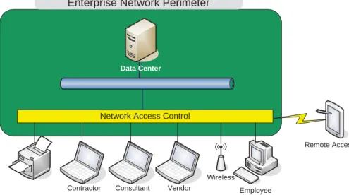
For the purpose of this paper, systems joining or existing at the ends of the enterprise network are referred to as endpoints. Technology advances have broadened the definition of what an endpoint system can be. Devices attempting to attach to the corporate network can include desktop computers, laptops, personal digital assistants, Smartphone, and other types of special equipment. Essentially any device that connects to the corporate network can be considered an endpoint device. Although servers and some similar systems do connect to the internal network, what is of primary concern are those systems that can be infected by malware from activities when detached from the internal network. These activities include email access, web browsing, instant messaging, and other activities performed through a public network (Mariwald, 2007, pp. 5-7).
Figure 1-1 illustrates a simplified view of an enterprise network that hosts a variety of employee and guest users, as well as remote users and other devices. The green area represents the internal or trusted network.
Data Center Printer ` Employee Vendor Contractor Consultant Wireless Remote Access
Enterprise Network Perimeter
Figure 1-1 - Enterprise Network Perimeter
Organizations use multiple strategies to mitigate the problems of access from within the internal network. Organizational security policies mandate that endpoint systems have the latest operating system patches, the most current antivirus signatures, and perhaps personal firewalls installed on the client system. However, there is no assurance that employees, especially those whose systems may spend a great deal of time off the corporate network, or home systems used to access the internal network through a SSL VPN or dial-up, adhere to the policy.
This mobility of enterprise users, the addition of guest users such as contractors and vendors attaching to the internal network, must eventually shrink the perimeter of the internal network back to the datacenter in order to protect the core information assets of the enterprise. Figure 1-2 illustrates the new perimeter.
Data Center Printer ` Employee Vendor Contractor Consultant Wireless Remote Access
Enterprise Network Perimeter
Network Access Control
Figure 1-2 - Reduced Perimeter Network
To address this issue, corporations are focusing on ensuring that an endpoint is compliant with the organization’s security policy at the time when it connects to the trusted network, and if it is not, to force remediation before allowing access. Access policy may require verification of the endpoint’s posture (is it “healthy”?), its security assessment (does it have the latest patch level and virus signatures?), and does the endpoint meet the access policy criteria (user and device identity, location, time-of-day, and other access policy requirements). To address this issue, corporations are evaluating, and in some cases, deploying NAC solutions.
The Network Endpoint Assessment Group (NEA) of the Internet Engineering Task Force (IETF) states in their NAC requirements document that “…network operators need a proactive mechanism to assess the state of systems joining or present on the network to determine their status relative to network compliance policies” (NEA Overview and Requirements, 2007).
1.2
What is Network Access Control
NAC is a concept that controls network access and network resource usage “based on user
authentication, endpoint behavior, and an assessment of the device’s identity and security properties” (Mariwald, 2007, p. 6).
User authentication identifies the user requesting access to the network. Typically this is done today through a user identifier and password, but can involve other factors of authentication, such as fingerprint or a security token like a JavaCard.
The security posture (health) of the endpoint is another aspect of the network security policy. This check ensures that the endpoint device has the latest operating system and application patches, current anti-virus signatures, a personal firewall enabled, and perhaps a requirement may also exist to ensure that no unauthorized applications are on the device (Sturdevant, 2007). Other areas that may determine access to the internal network could be the user’s group membership, the time of day, and the user’s authorization to access the network.
Device identity and security properties may also govern the level of access and resources that are permitted. Before an endpoint is allowed onto the network, or the use of a network resource, its compliance to the network access-control security policy should be checked. The network access-control policy can cover a wide spectrum of control choices from a simple GO-NO GO decision on network access, or it can involve complex rules, such as the parts of the network accessible to the endpoint (Snyder, 2006).
When fully implemented, NAC will be able to apply policy across (1) the wired and wireless local area network (LAN), (2) SSL Virtual Private Network (VPN) remote access where a single user is executing IPsec or SSL VPN client, and (3) VPN-connected site-to-site (perhaps from a branch office) (Getting Started, 2006).
1.3
Why use Network Access Control
NAC is one attempt to reestablish the network perimeter. This control can occur before an endpoint device is allowed onto the network, and it can also be an ongoing evaluation of the endpoint during the time it is accessing the network. This is normally referred to as preadmission and postadmission assessment, respectively.
Enterprises have a strategic need to control access to their networks which by extension controls access to their information and application resources. NAC attempts to solve the following four problems:
User and endpoint identification and authentication
Security policy criteria for accessing network resources. This can include user identity, device configuration, or device security posture.
Limit access or quarantine devices that do not meet security policy criteria
Ability to remediate a device before allowing unrestricted access to network resources (Maiwald, 2007)
Restrict nonemployee access to network
Restricting access based on the endpoint security posture (does it have a virus?) Regulatory compliance: Sarbanes-Oxley Act (SOX), Health Insurance Portability and Accountability Act (HIPAA), and other regulatory requirements
Restrict user network access based on the “health” or security posture of the endpoint device (Maiwald, 2007, p. 7)
Universities have seen the greatest need for NAC solution because the students typically own their own computers, and in many cases these computers could be infected with viruses before joining the university network. In the past the university was not able to enforce network policy that would require anti-virus software but with NAC, this is changing. Arizona State University deployed Cisco’s Clean Access technology to scan each computer before it joins the network to ensure that it adheres to network security policy. Non-compliant computers are quarantined until automated processes can bring the computer into compliance (Burger, 2007).
1.4
Who is offering Network Access Control
Three existing or emerging architectures address the problems described – Cisco’s Network Admission Control (NAC), Microsoft’s Network Access Protection (NAP), and The Trusted Computing Group’s Trusted Network Connect (TNC) have products or proposals to address this issue with similar but different technology frameworks. Each has its supporters, and in many cases, many partners are hedging their bets by implementing support for each framework.
To help the interoperability of the different approaches, the IETF NEA Group is looking at defining a layer of communication to bridge the gaps between these competing architectures. Also to address the problem of interoperability, in 2006, Cisco and Microsoft agreed to have their two frameworks interoperate, and in May, 2007, TCG TNC and Microsoft introduced a change to the TNC specification to interoperate with Microsoft NAP.
In addition to the frameworks, there are a plethora of small companies offering NAC appliances that target some aspect of NAC but many of these are islands within the manageability ocean. Network administrators are often forced to have multiple tools to manage all of the devices on their network.
The absence of a single standard for NAC, and the fact that Microsoft will not release NAP until Windows Server 2008 timeframe, has many corporations either undecided about the correct direction or dealing with the complications of deploying in a world with multiple standards. A recent Forrester report indicated that
“implementations are proving difficult and impractical” (Seltzer, 2007).
1.5
Organization of Material
The topic of this paper, policy-based network access control, is very complex and involves numerous aspects of network architecture. A building block approach to the topic is adopted so that each chapter lays a foundation for the discussion in succeeding chapters.
Chapter Four begins with a brief discussion of the important components used by NAC. This includes network policy, security protocols, and some key requirements of network infrastructure.
Chapter Five adds information about how network access can be controlled. This includes discussions about endpoint agents, Dynamic Host Control Protocol (DHCP), out-of-band security devices, in-band security devices, cryptographic overlays, and network infrastructure devices.
Chapter Six uses the information in Chapters Four and Five as a basis for the discussion for NAC frameworks and appliances.
With an understanding of the technologies involved and the complexities of NAC, Chapter Seven discusses the concerns with the current NAC solutions. This discussion begins with the level of control and ownership that an organization has over their network, followed by a discussion of agent-based endpoint control, network
architectural considers, complexities associated with NAC follows, and concludes with a discussion on interoperability deficiencies.
2
Terms
Term Definition
preadmission assessment
An endpoint device is evaluated before admittance to the network is allowed. If the assessment is within the network policy, full control is normally allowed. If the device is not compliant with network policy, restricted access or forced remediation is normally the result. postadmission assessment
Continuous assessment of endpoint devices after access to the trusted network. If the device fails to meet policy, a log of this event can be made or the endpoint’s access can be revoked until the issue is corrected.
AAA
Authentication, Authorization, and Accounting. Authentication confirms that the user requesting access to network resources is a valid user.
Authorization determines if the valid user making the request to use network resources or services has the rights to use those resources or services. Accounting tracks the consumption of resources by users. Authentication or Log-in
screen
A user-interface control that solicits and captures a user’s credentials required for network authentication.
Authenticator
The authenticator acts as a gatekeeper that stands between the
supplicant and authentication server and will only allow the supplicant to access the network once the supplicant has been successfully
authenticated.
Authentication server Provides an authentication service that performs for the actual authentication of the supplicant, user, or endpoint device. CHAP Challenge Handshake Authentication Protocol.
Cryptographic overlays Appliances or endpoints use cryptographic mechanisms to limit access to network resources.
DHCP Dynamic Host Configuration Protocol. A component of the TCP/IP protocol that assigns IP address.
DHCP enforcement Enforces network policy at the time that an endpoint requests an IP address.
EAP
Extensible Authentication Protocol. A framework that facilitates the instantiation of security protocols within (on top of) the IPsec framework. Provides for additional authentication.
Endpoint agents Software agents on the endpoint enforce connection policy. Extranet A network that allows access to trusted external users.
In-band security device A device placed in the path of network traffic where it can monitor and make policy decisions to block network traffic.
Internet A worldwide, publically accessible interconnection of business, academic, and government networks.
intranet A trusted network that has the characteristics of the Internet but only allows access to trusted inside users.
LAN Local Area Network. A computer network that covers a relatively small geographical area such as a home, office, or group of buildings. Network infrastructure
enforcement
Access policy decisions are enforced by network devices, such as an 802.1x Ethernet switch.
Network policy
Establishes the criteria for allowing an endpoint to access the network and typically contains (1) a set of usage rules, (2) an authorized user's specific set of parameters, or (3) network access criteria.
network device on one network segment to a network device on another network segment.
Network Switch Port A network interface on a switch that provides for a single point of connection to the network.
Network packet
A block of data that is communicated over a computer network and consists of protocol control information (PCI), which contains source and destination addresses, checksums, and sequencing information. The packet also contains the user data that is often referred to as payload. Out-of-band device
A device that monitors network traffic from outside the normal network traffic stream or responds to alert messages from network switches or other network infrastructure components.
PAP Password Authentication Protocol. A simple protocol used to authenticate to a network access server.
PPP Point to Point Protocol. Encapsulates TCP/IP and other traffic so that it can be transmitted over telephone lines.
Port-based authentication
An IEEE 802.1x mechanism that configures a network switch to allow access only to authorized users connecting through the port on the switch, and to deny access to all other users.
RADIUS Remote Authentication Dial-In Service. Provides for centralized authentication and access control in a client / server environment. Supplicant The user or endpoint requesting authentication.
VLAN Virtual Local Area Network. Segmentation of a physical network into one or more logical networks.
VPN Virtual Private Network. A secure, private connection through a public unsecure network, which is typically the Internet.
WAN Wide Area Network. A computer network that covers a wide geographical area.
WLAN
Wireless Local Area Network. A computer network that covers a relatively small geographical area such as a home, office, or group of buildings and links computers without the use of wires.
3
Research Methodology
This professional project used several research methods during its development. These methods can be broadly categorized into (1) search strategy, (2) evaluation, and (3) managing information (Hacker, 2003).
The search strategy used a systematic plan for locating sources. The search strategy consisted of searching the databases for academic and refereed journal articles. Examples of these databases are ACM Digital Library, ACM Portal, Computer Database, Computing Reviews, InfoTrac OneFile, and Wiley Interscience.
Additionally, consulting firms, such as the Barton Group, which specializes in information security and produces numerous research papers on the topic, was utilized.
Since this professional project topic is specific to three primary architectures of Network Access Control (NAC) frameworks and products, information posted on the Cisco, Juniper, and Microsoft web sites was also used. Information from the Trusted Computing Group’s web site that relates to the Trusted Network Connection (TNC) framework and the Network Endpoint Assessment Group of the Internet Engineering Task Force was used in preparing this professional project.
Industry web sites, such as CIO, ComputerWorld, InfoWorld, and NetworkWorld were used to research the current trends and developments in NAC.
Book sources were used, and accessed primarily through Books24x7 and Regis Library Online. In limited cases, online discussion, blogs, or other collaborative areas that contain expert information were used.
Government web sites such as NSA or other security-oriented organizations were referenced. Lastly, Google and other search engines were extensively used to search the web for source material. Material found through this method was closely evaluated for impartiality and validity.
Source material must be relevant, scholarly, and current (the field is emerging and the latest information was used). Relevant material in many cases contained NAC, NAP, or TNC in the title or abstract. Scholarly material was from a recognized journal or educational site (recognized college / university) and the article was well-written and documented with footnotes and a bibliography (Hacker, 2003).
As information was evaluated, it was reviewed as to how well it applies to the thesis question, whether it was a primary or secondary source, if there was any bias in the article or source, and a careful assessment of the author’s arguments was made (Hacker, 2003).
Since network access control is emerging technology, there is a great deal of information on the web, and this information covers the full spectrum, from very good to very bad. It was important to understand any agenda that the site had in promoting their viewpoint. For example, CISCO’s web site is concerned with selling their network admission control approach to NAC. Their literature is biased toward their solutions. This isl not be a reason to dismiss this site as a source, only to weigh the information against any bias in the information. So Web sources were evaluated for authorship, sponsorship, purpose and audience, and currency (Hacker, 2003).
A great deal of information was collected, and a careful and accurate record as to the source of the information was maintained. It was important to maintain a bibliography, track source materials, and record information about the content of the source without plagiarizing. This professional project will use the APA format for its bibliography (Hacker, 2003).
Source materials were printed or photocopied and categorized in a three-ring binder. There are several benefits to this approach, but the main one is that the original material is always available to ensure that information has not been inadvertently plagiarized. Material from the Web was downloaded and stored locally.
The final stage of managing information was to record notes about the article. Recording notes can summarize information, paraphrase the information, or quote the information. Summarizing reduces the totality of an article or book chapter to a short paragraph or single sentence. While summarizing reduces the information to the key or important points, paraphrasing rewrites the information in different words. Key phrases that are used without change are quoted. In any event, information used directly from a source is quoted (Hacker, 2003).
4
Components of NAC
The current NAC implementations can use a broad array of technologies, which themselves rely on other basic and complex technologies. In this section some of these technologies are introduced.
The discussion begins with a brief overview of network policy as it relates to access control. The
discussion continues with an overview of a few of the important security protocols used between network devices. As part of this discussion, an overview of encryption is introduced that explains the difference between public and private key encryption. The chapter concludes with a discussion about some key infrastructure components used by NAC.
4.1
Network Access Policy
Network Policy Enforcement establishes the criteria for allowing an endpoint to access the network. A policy can be (1) a set of usage rules, (2) an authorized user's specific set of parameters, or (3) network access criteria (Thayer, 2005).
The policy will be enforced using technology that can block access at the network entry point, or force access to a restricted network or remediation server until the endpoint meets the policy’s minimum requirements.
The Network Policy Enforcement Point is as its name indicates: the place where the policy is enforced. This can be an in-band network device which may block all access or force an endpoint to a remediation
infrastructure. It can also use 802.1x-aware switches, or access points, and 802.1x aware client systems to control the VLAN that an endpoint is assigned to. Lastly, it can use a web browser to redirect all endpoint traffic to a specific web portal until the endpoint is compliant (Thayer, 2005).
The Policy Enforcement Point will typically require a policy infrastructure that supports back-end authentication, a security event management mechanism, and a centralized policy store to control policy
distribution. These can be a LDAP server, Active Directory, or policy data embedded in RADIUS data (Thayer, 2005).
NAC solutions can make use of several different network communication protocols to facilitate the movement of information between devices. This is a huge subject that currently fills countless volumes so this section will focus on a limited number of areas that are used in many NAC implementations.
4.2.1
OSI Reference Model
Before beginning the actual discussion of the network protocols used, it is important to discuss what is meant by a network protocol. For this paper’s purpose, a network protocol can be defined as a “standard set of rules that determines how systems will communicate across networks” (Harris, pg. 417).
In order to allow interoperability between various devices that communicate over the network, the International Standards Organization (ISO), a worldwide federation, established in the 1980s, defined an abstract framework. This is known as the Open Systems Interconnection Model, or more commonly referred to as OSI, and is described in ISO Standard 7498.
Each of the boxes in the graphic on the left represents a logical layer which has its own protocol where each one of these protocols has very specific responsibilities. Each layer can communicate with the layers above and below it, as well as the same layer in another device. As a message moves down the stack, control information is added to the contents from above. As a received packet or message moves up the stack, this control information is removed,
If there were two devices, device A and device B, the Application layer of device A would communicate to the Application layer of device B. The same is true for each of the other layers in the graphic.
Figure 4-1 - OSI Reference Model
Because computers and other devices that communicate over a network do so primarily through an electrical connection, a physical connection does not exist between say, application layer to application layer for two devices that are communicating. Instead, the connection exists at the physical layer and the layers above are encapsulated within a data package that is sent between two devices.
In a typical scenario, two devices want to communicate. The Application layer of device A constructs a message and passes it to the Presentation layer. It adds some information and passes it down to the next layer and
Application Session Transport Presentation Network Data Link Physical
it adds some information. This continues until it reaches the Physical layer. The total data package is sent on the wire or by radio waves to device B. The package is received by the Physical layer on device B. This layer strips off the information added by device A’s Physical layer and passes it up to the Data Link layer. It in turn takes off device A Data Link layer information and passes the package to the next higher layer. This repeats until it reaches the device B Application layer where what is received is the message from device A’s Application layer.
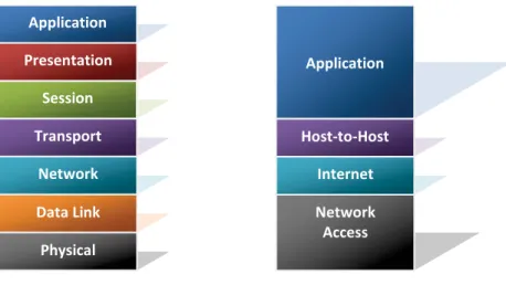
While the OSI model is an abstract construct, one concrete protocol construct that will be referenced several times in this paper is the TCP/IP protocol stack.
Figure 4-2 - OSI and TCP networking models
As can be seen from the comparison in Figure 4-2, the TCP/IP protocol stack does not contain all eight layers of the OSI model. The Application layer in TCP/IP performs the role of the Application, Presentation, and Session layers in the OSI model. Similarly the other layers of the OSI stack map to the layers shown in the TCP/IP model.
It is beyond the scope of this paper to provide a detail explanation of each layer, but the model should provide a helpful reference during the discussion of the protocols in this chapter.
Before examining the first protocol, however, it is important to discuss encryption.
4.2.2
Encryption
Encryption is a method of converting readable information, termed plaintext, into a form where the contents are no longer recognizable and may even appear to be random or scrambled. The words in a newspaper
Application Session Transport Presentation Network Data Link Physical Application Host-to-Host Internet Network Access
story are plaintext, but if numbers were substituted for each letter of the alphabet, such that a ‘1’ represented an ‘A’, and other numbers represented the remaining letters, then the newspaper story would no longer be readable and the jumble of numbers in the story would be termed ciphertext. So the essence of encryption is the process of converting plaintext into ciphertext.
When this technique is applied to a message from one person to another, then only the intended recipient can read the letter as long as the sender had previously communicated the method used to change the text. The method used to jumble the letters is referred to as an algorithm, which specifies the rules that instructs how to create the ciphertext and also how to retrieve the plaintext from the ciphertext.
While a clever algorithm may work in simple circumstances to hide a message, another element is needed in modern encryption systems to protect the contents of message from a determined effort to read the message, and this is called an encryption key.
It is helpful to draw a comparison between an algorithm, which is normally known by a large number of people, to that of a mechanical lock that is mass-produced and also used by a large number of people. The one aspect that makes the lock usable by so many is the fact that a different key is used to open each different lock. The same principal applies to encryption. A unique key is created that works with the algorithm to create an encrypted message. A key that someone else has will not reveal the contents of the encrypted message. Each key is different and a message encrypted by one key will not ‘unlock’ a message created by a different key.
4.2.2.1 Encryption Keys
There are two different types of encryption keys used in NAC implementations. To continue with the lock analogy, if for any given lock there was a single key that could lock and unlock it, that key could be thought of as
symmetric, that is, the same key works for both locking and unlocking operations. If on the other hand, a special
lock existed where it took one key to lock the lock, and a different one to unlock the lock, then these keys could be considered asymmetric because they would only perform one part of total functions required.
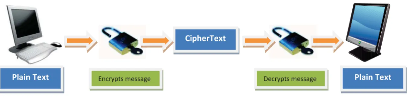
In the discussion about algorithms, only one type of key was considered, and this was a key that was used to encrypt and to decrypt a message. This type of algorithm would be considered a symmetric algorithm that uses a symmetric key. Figure 4-3 illustrates this concept.
Figure 4-3 - Symmetric encryption
A second type of algorithm also exists. This is one where two keys are needed to perform the encryption and decryption. This algorithm is called an asymmetric algorithm and uses asymmetric keys, called public and private keys. In the first use case for asymmetric encryption, the public key encrypts a message and the receiver uses the private key to decrypt it. This provides message confidentiality. Figure 4-4 illustrates asymmetric encryption.
Figure 4-4 - Asymmetric encryption
In the second case, the private key encrypts the message and the receiver uses the sender’s public key to decrypt it. In this case authenticity of the sender and nonrepudiation is the primary benefit. If it can be decrypted, then we can be assured that the message came from the sender. Of course this assumes that the sender is the only one with knowledge of the private key.
Each of these algorithms have strengths and weaknesses which make them ideal for different tasks as will be seen in the remainder of this paper. Symmetric encryption is faster and more secure than asymmetric
encryption so it is typically used for large jobs like encrypting large amounts of text or data. On the other hand,
CipherText
Private key decrypts message
Plain Text encrypts message Public key Plain Text
CipherText
Decrypts message
asymmetric encryption is better for distributing keys and provides for authentication and nonrepudiation (Harris, pg. 612).
The strengths of these two encryption methods can be linked to provide a secure key distribution system. Because symmetric encryption is much faster in processing large amounts of information than the asymmetric encryption, it should be used for encrypting the main traffic in any secure session. The problem is that the symmetric key must be present on both ends for this to work. To address this problem, asymmetric encryption is used to encrypt a symmetric key so that it can safely be transmitted to another site. Thus the strengths of both have been used to create a secure key distribution system. This will be discussed further.
4.2.2.2 Digital Signatures
A digital signature ensures that the contents of a message have not been modified since the signature was created. A digital signature employs a cryptographic hash function to create a unique value that represents the contents of the message.
For example, if I wanted to communicate the message, “The day is beautiful,” but I also wanted the receiver of this message to be able to determine if the message had been changed, I could create a numerical value that the receiver could use to ensure that the message had not been changed to “The day is rainy.” This numerical value used is referred to as a hash value.
A hash value creates a fixed-length value from a variable number of characters. It uses a special type of algorithm known as a one-way function. An interesting fact about a one-way function is that it relatively easy to compute in one direction, but almost impossible to do so in the opposite direction. The hash value is can also be referred to as a message digest.
When someone receives a message with an associated message digest, the receiver can compute a new message digest for the message and compare it to the received message digest. If these values are the same, then the receiver has some assurance that the message has not been changed. The exception to this is if a malicious party intercepted the message, changed it, and computed a new message digest on the changed message.
To prevent the changing of the message and the associated message digest, the message digest is encrypted with the sender’s private key (the secret part of the asymmetric key pair) discussed in the previous
section. The encrypted message digest becomes a digital signature. Figure 4-5 describes the process for creating a digital signature. ` Sender Message created by sender
Hash value computed on message contents
Hash value encrypted with senders private
key message signature ` Receiver message signature Signature decrypted
using sender’s public
key = sender’s hash
value
Hash value computed on received message When the two hash
values are the same, then the message has
not been altered
Figure 4-5 - Creating a digital signature
When the message and digital signature are received by a recipient, a new hash value (message digest) is computed for the received message. The sender’s public key is used to decrypt the received digital signature. The decrypted hash value is compared to the computed hash value, and if they match, the sender knows that the message has not been altered and that it is from the expected sender.
A digital signature provides sender authentication, integrity checking, and prevents the sender from repudiating the message because the hash value was encrypted using the sender’s private key. Signatures will be used in a future discussion about digital certificates.
4.2.2.3 Public Key Infrastructure
Public Key Infrastructure (PKI) is “the set of security services that enables the use of public key
cryptography and X.509 certificates in a distributed computing system” (Diodati, p. 7). The current specification for PKI is published in Internet Certificate and CRL Profile RFC3280.
The impetus for public key cryptography was the ability to enable secure communication between parties in an open environment using an encryption key that can be conveyed over non-secure communications (Barr, 2004).
The parts of PKI can roughly be divided into the following areas: endpoints, Certification Authority, Registration Authority, Repository, and Certificate Revocation List (CRL) Issuer (Barr, 2004).
Endpoints can be anything that is the subject in a public key certificate. This can be an actual end-user, a device such as a router or server, or a software process (application). An endpoint can be either a consumer of PKI services or a provider.
For an endpoint to participate in PKI, it must have a digital certificate. The X.509 standard defines how a certificate is created. The certificate is issued by a trusted third party that is referred to as a Certificate Authority (CA). The certificate is a digital document that validates the sender's authorization and name, and contains the certificate holder's name, public key, and the Certification Authority's digital signature, which is used to
authenticate the certificate. A certificate is only meaningful to another entity when the issuer of the certificate can be trusted.
To understand the basic workings of PKI, it can be helpful to relate the activities to a real world example like the passport system. When a person wants to acquire a passport, they must provide documentation that validates they are who they purport to be. If the proof is accepted by the registering authority (passport office) then their information is added to a list of valid passports (repository). Eventually a passport is created and given to the requestor by a different part of the passport service that certifies that the person described in the passport has proven their identity. In time, the passport may expire or the person may commit a crime that requires that their passport is invalidated. When this occurs, information is entered in the passport repository about the revoked status of the passport. The passport service can then create a list of invalid or revoked passports by looking in the repository. This list could be referred to as the passport revocation list and made available to organizations that use the passport as an assurance of identity, such as the custom service. PKI provides similar services with slightly different names.
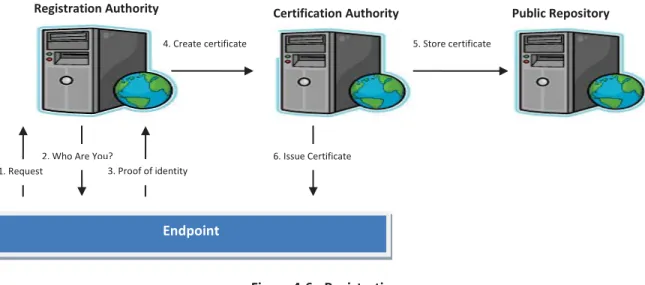
When an endpoint requires a digital certificate, valid documentation is provided to a Certificate
Registration Authority that proves the identity of the endpoint. This information is recorded in a repository, and a Certification Authority issues a digital certificate with the certificate holder's name and public key, along with the endpoint’s digital signature. Figure 4-6 illustrates this process.
Figure 4-6 - Registration
When this certificate is presented to a PKI service, if it trusts the Certification Authority that issued the certificate, then the certificate is accepted as proof of the presenter’s identity. Referring back to the passport scenario, this is analogous to a traveler presenting passport at the border of a country. If the country’s custom service trusts the issuer of the passport, then the traveler is granted admittance.
Once a certificate is issued, it is critical that a record be maintained about the contents of the certificate. This is normally the role of a repository, which is a method for storing and retrieving PKI-related information, such as public key certificates and Certificate Revocation Lists (CRL). Practically, this can be something as low tech as a flat file or as robust as an implementation of a X.500-based directory with client access via the Lightweight Directory Access Protocol (LDAP).
Also important is the ability to revoke a certificate when it is no longer valid. In PKI this is accomplished through the use of the CRL. In most implementations, the CA is responsible for maintaining and providing a list of certificates that are no longer valid, but this can be optionally assigned to another service called Online Certificate Status Protocol (OCSP) that can check a CAs CRL during the certificate validation process. This of course would be equivalent to the customs service checking its repository to ensure that a presented passport is valid.
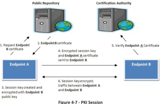
It will be illustrative at this point to discuss the major steps that take place during a PKI session, but before that happens a new term – session key – needs some explanation.
Request
Endpoint
Registration Authority Certification Authority
2. Who Are You?
3. Proof of identity 1. Request 4. Create certificate 6. Issue Certificate Public Repository 5. Store certificate
A simple definition for session key is a symmetric key that two endpoints use to encrypt messages. From our previous discuss of symmetric encryption you’ll recall that the same key is used to encrypt and decrypt
messages. One of the unique properties of a session key is that it is only used during a single session, and after that it is discarded. This provides for more secure exchange because the key will only exist for a relatively short time.
Figure 4-7 - PKI Session
Referring to the example in Figure 4-7 - PKI Session, there are two participants: Endpoint A and Endpoint B. Recall that an endpoint can be an end-user, a device, or a software process.
1. A session begins when Endpoint A requests Endpoint B’s digital certificate from the PKI repository.
2. The Public Repository where certificates are stored returns Endpoint B’s certificate, which also includes Endpoint B’s public key.
3. Endpoint A creates a symmetric or session key that can only be used during the communication’s session with Endpoint B. The session key is then encrypted with Endpoint B’s public key.
4. The encrypted session key plus Endpoint A’s digital certificate is sent to Endpoint B. 5. Using the information from Endpoint A’s certificate, Endpoint B requests that the issuing CA
6. Once this is done, Endpoint A and Endpoint B have established a session, and the session key will be used to encrypt all traffic between them. Once the session is completed, the session key is discarded and the session infrastructure is disassembled. If these two endpoints need to communicate again, a new session will be created.
This represents one type of key exchange or key establishment. The other key establishment occurs when both parties contribute to the key generation. This is known as key agreement.
4.2.2.3.1Benefits and Challenges
In the discussion thus far, several PKI benefits have been revealed. These include the ability to enable confidentiality of information, ensure data integrity, authenticate the parties in the exchange of information, and non-repudiation (remove the ability of one party to deny that an exchange took place).
From the description of so many moving parts, the careful reader has probably also determined that there may be some barriers to PKI deployment. These barriers are total cost of ownership (TCO), lack of maturity, complexity and uncertainty, repository issues, lack of industry standards, multi-vendor interoperability, and scalability and performance (Barr, 2004).
The TCO of PKI can be very significant because of the number of hardware components involved in a typical installation, the cost of software and support tools, the leveragability of the existing corporate IT
infrastructure, the cost associated with planning, deployment, operation, and maintenance of infrastructure, the costs of defining policies and procedures needed with a PKI deployment, any additional facilities that are needed to support PKI, the training costs for PKI development, deployment and maintenance, the cost of administrative support, the problems or lack of interoperability with other vendor PKIs, and liability protection. While this list is not exhaustive, it does illustrate the many areas that must be considered when estimating the cost of PKI (2004).
There is not a consensus in the industry as to the maturity of PKI. Some believe that PKI is an emerging technology with all the problems that that entails, but others maintain that PKI is a must-have technology (2004).
Complexity and uncertainty should also be a concern for organizations considering PKI deployment. Many believe that PKI is too complicated and expensive to be viable. Because of this uncertainty, experts generally
recommend that small PKI pilots should be deployed first to address a small community or single application (2004).
Distribution and revocation of certificates, as well as other PKI-related information, from online repositories can also be problematic (2004).
The lack of industry standards for directory services that offer PKI services has also been a concern. Lastly, because few large-scale PKI deployments have been completed, scalability and performance issues associated with repository services are unknown (2004).
This section has presented a brief description of Public Key Infrastructure and its major component parts. This was not meant to be an exhaustive treatment of the subject, but to only introduce the concept and
complexities of PKI. As will become evident, PKI can be but one part of the complexity of a NAC solution.
4.2.3
Secure Sockets Layer (SSL)
Netscape Corporation developed Secure Sockets Layer (SSL) to facilitate the secure transmission of documents over the Internet. Today most browsers support SSL. Data encryption, integrity checking, server authentication, and optionally, client authentication, are supported by SSL.
SSL is composed of two protocols, where one works at the lower part of the OSI session layer, and the other works at the top of the OSI transport layer. The first protocol is SSL Record Protocol and the second is standard HTTP. Basic security and communication services are provided by SSL Record Protocol to the top layers of the SSL protocol stack. Standard Internet communication services are provided to the server and client by HTTP (Whitman and Mattord, pg. 376; Harris, pg. 667).
A SSL session is primarily divided into two parts. The first involves a handshaking exchange to setup the session and establish the security parameters that will be used. In the second part, data is securely exchanged using the environment established during handshaking. During a typical SSL session the following exchange will take place.
Handshaking:
2. Server offers SSL session 3. Client sends security parameters
4. Server compares received parameters against its own until a match is found 5. Server sends its digital certificate to client
6. Client evaluates certificate and decides to trust server 7. Optionally: Server requests client certificate
SSL session established:
8. Client generates a session key and encrypts it with server public key (note: only the server private key can descript the session key)
9. Encrypted key sent to server
10. Session Key used to encrypt data during session
In the typical session, only the server is authenticated. This normally occurs with Internet shopping today. When an SSL session is in effect, the user can confirm this by observing that the URL contains “HTTPS” and a padlock or key icon appears at the bottom corner of the browser. When the server does request the client certificate, this is referred to as client-side authentication (Hook, 2005; Harris, pg. 667).
4.2.3.1 Transport Layer Security (TLS)
Transport Layer Security (TLS) provides privacy, integrity, and proof of authenticity. Privacy is provided because the information between the client and server is encrypted within the session. Integrity is provided because any change to the content between client and server is immediately known. Proof of authenticity is provided when the client and server exchange certificates that can be verified with a trusted third-party certificate authority which can validate the authenticity of the endpoints involved (Hildebrandt and Koetter, 2005; Ciampa, pp. 210-211).
TLS version 1.0 was essentially the same as SSL version 3.0. While TLS 1.0 is derived from SSL 3.0, these two protocols don’t interoperate easily. However, TLS 1.0 does contain the ability to regress to SSL 3.0
Like the SSL protocol, TLS contains multiple protocols, but for the purposes of this discussion, these can be reduced to two primary areas. TLS Handshake Protocol is used to perform authentication between a server and a client, establish the encryption algorithm that will be used, and exchange the cryptographic key that will be used during the session (Oppliger, 2003; Johnston and Piscitello, 2006; Ciampa, pp. 210-211).
The TLS Record Protocol fragments messages into TLS records, computes a message authentication code (MAC) and appends this to the record, encrypts the combined result, and then transmits it (Oppliger, 2003; Johnston and Piscitello, 2006; Ciampa, pp. 210-211). MAC combines a cryptographic hash function and a symmetric key to produce a value that can be used to verify message integrity and authenticity (Oppliger, 2003). Figure 4-8 illustrates a typical TLS session.
Server
`
Client
(1) Client connects to server (2) Server offers TLS session
(3) Client responds with TLS (4) Server sends its certifcate
(6) encrypted session (5) Client verifies
server certificate against its list of root certificates.
Figure 4-8 - TLS Session
A PKI is needed when either SSL or TLS is enabled in a web server environment. This requires that the client and server devices have certificate configuration (Schurman, Thomas, and Christian, 2006).
4.2.4
Tunneling Protocols
There is a class of protocols that are used to communicate other protocols over mediums where these protocols normally can’t be used. This is accomplished by creating a virtual network path where protocol information or packets from one protocol are encapsulated within that of another protocol. Sometimes these encapsulated protocols are also encrypted. This is referred to as tunneling (Harris, p. 540).
For example, if network 1 wanted to communicate with network 2, but these two networks were not connected by a LAN, and the protocol on the network 1 only knew how to communicate over a LAN, then one way for the two networks to communicate would be over a telephone connection. But since the network protocols do not know how to communicate over a telephone line, another protocol could be used to wrap or encapsulate the network protocol as it travelled over the telephone network between the two networks.
In a sense it is like a letter sent through the postal service. The post office would not be able to deliver the contents of the letter without an envelope. The envelope protects the letter inside and also provides information that the postal service needs to move the letter from the sender to the receiver. The letter has been encapsulated by the envelope to allow this transference. When the receiver receives the envelope, the letter inside is removed and read by the receiver. This is also what happens when a message from the network 1 is transferred over the telephone network to network 2.
Four different tunneling protocols are discussed.
4.2.4.1 Point-to-Point Protocol
Point-to-Point Protocol (PPP) encapsulates TCP/IP and other traffic so that it can be transmitted over telephone lines. PPP is used when accessing the Internet through a dial-up connection that is hosted by an Internet Service Provider (ISP). PPP and ISP are important for corporate network access because an employee can dial into a local ISP instead of a possible long distance charge into the corporate facility. PPP will be used to facilitate three tunneling protocols: PPTP, L2TP, and IPsec (Harris, pp. 541-542).
4.2.4.2 Point to Point Tunneling Protocol
Point-to-Point Tunneling Protocol (PPTP) was developed by Microsoft Corporation to allow a remote user to use the Internet securely by establishing a PPP connection to an ISP and then to create a secure virtual private network (VPN) or tunnel over the Internet to a destination. To secure the transmission of data, the PPP payload is encrypted by a key that is established during the authentication process. The user data is encapsulated within the PPP payload. PPTP allows the PPP data to be communicated over the Internet where PPP is not supported (Harris, pg. 543).
4.2.4.3 Layer 2 Tunneling Protocol
One limitation of PPTP is that it can only work over IP networks, but many other types of networks are used to move data. These include frame relay, X.25, and ATM links. To address this issue Cisco Corporation developed Layer 2 Tunneling Protocol (L2TP) which combines some of the best features of PPTP. L2TP
encapsulates the PPP payload but does not provide for encryption of the payload. If this is required, then L2TP needs to be combined with IPsec, the next topic discussed (Harris, p. 544).
4.2.4.4 Internet Protocol Security (IPsec)
Internet Protocol Security (IPsec) is an open source protocol within the TCP/IP family of protocols used for secure communicates across an IP-based LAN, WAN, and Internet networks between two devices (two servers, two routers, client / server or possibly two gateways). IPsec is a creation of the IETF's IP Protocol Security Working Group and is normally used to establish virtual private networks (VPN) across the Internet between networks (Harris, p. 672; Whitman and Mattord, pg. 378).
Although IPsec has protocol in its name, it is normally considered more of a framework rather than a protocol. It defines the type of algorithms, keys, authentication requirements that must be used. Authentication Header (AH) and Encapsulating Security Payload (ESP) are the two protocols that IPsec uses. While ESP provides cryptographic means to provide source authentication, confidentiality, and message integrity, AH is only an authenticating protocol. A company will use AH when the source of the sender is required and when the integrity of the message information needs to be assured. ESP is used to gain the advantage of AH plus confidentiality, which is attained through encryption of the message information. For this reason, ESP is almost always used when setting up a VPN (Harris, p. 672; Whitman and Mattord, pg. 379).
The reader may wonder why AH would ever be used since ESP offers the same authentication and integrity services as AH. The use of one over the other is particular to the type of environment in which IPsec is used. Specifically, if the IPsec packet passes through Network Address Translation (NAT) device, then ESP must be used because NAT will modify the packet header when it changes the IP address of the packet. Because the packet contains an integrity check value (ICV), which computes a unique value depending of the contents of the IPsec packet, the changed ICV will cause the packet to be discarded by the receiver (Harris, 672, 674).
In addition to these two protocols, IPsec has two modes it can operate in. Transport mode protects the payload of a message and will be used when the network packet must pass through a NAT device, which allows the source and destination IP addresses to be visible (not encrypted). In transport mode intermediate nodes can read the IP headers but the actual IP data is encrypted (Whitman and Mattord, pp. 378-380; Ciampa, pp. 238-239; Harris, pp. 672-674).
In tunnel mode the message payload, header, and trailer information are protected. Tunnel mode is used when the source and destination IP addresses do not need to be visible, such as between gateways. In tunnel mode systems, the beginning and ending of a tunnel act as proxies to send and receive the fully encrypted packets which have been encapsulated in a new packet. The proxies will decrypt the packet and send it on to the
destination in the original packet (Whitman and Mattord, pp. 378-380; Ciampa, pp. 238-239; Harris, pp. 672-674). In order to manage the device configuration information during an IPsec connection, a security
association (SA) is created for both the incoming connection and outgoing connection the device is using. Information contained in an SA will include the (1) lifetime of the SA, (2) mode (tunneling or transport), (3) ESP encryption algorithm and key, (4) ESP authentication algorithm and key, and other parameters needed to manage the connection between devices. The SA is referenced when an IPsec packet is received during a connection and the SA will define how the packet should be decrypted or authenticated (Harris, pp. 673-674).
To organize the various SAs during multiple communication sessions, the security parameter index (SPI) is used. Each IPsec packet contains a SPI value in its header information. This index is used to reference a security policy database where all the incoming and outgoing SAs are stored. The encrypted IPsec packet is decrypted and authenticated based on the parameters in the associated SA (p. 673).
The last aspect of IPsec discussed in this section is the management of keys. This can be accomplished manually or automated through a key management protocol. IPsec uses Internet Key Exchange (IKE) as its standard for key management. IKE uses an asymmetric-based key exchange and also negotiates security associations. IKE is a combination of two other protocols: Internet Security Association and Key Management Protocol (ISAKMP) and OAKLEY. ISAKMP defines a framework of exactly what can be negotiated during the establishment of an IPsec connection. This negotiation will include type of algorithm used, protocols used, modes, and keys. The OAKLEY
protocol actually performs the negotiation. These protocols operate at the network layer of the OSI reference model (Harris, pg. 674; Whitman and Mattord, p. 379).
The cryptosystems that IPsec uses in its operations are (Whitman and Mattord, p. 379): Diffie-Hellman key exchange: derives key material between peers on a public network
Public key cryptography: guarantees identity of two parties through the signing of Diffie-Hellman exchanges.
Symmetric encryption: bulk encryption algorithms like Data Encryption Standard (DES) Digital Certificates: signed by trusted certificate authority
4.2.4.5 Extensible Authentication Protocol (EAP)
Extensible Authentication Protocol (EAP) is a framework that facilitates the instantiation of security protocols within (on top of) the IPsec framework. By itself, EAP is made up of packet formats and a basic
handshake which cannot address the authentication between two entities. However, EAP's real strength is that it can wrap authentication protocols in a common format without regard to the underlying communications medium (Hardjono and Dondeti, 2005). EAP is described in detail in the IETF 3748 document (Aboba et al., 2004).
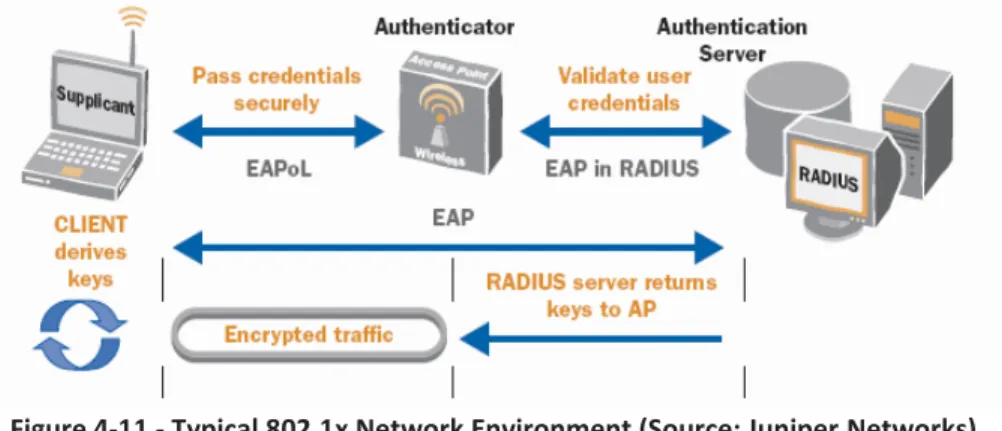
EAP can be used on wired or wireless networks, and on switched or dedicated circuits. IEEE 802.1x describes EAP encapsulation on wired networks, and IEEE 802.11i describes EAP for wireless LANs.
EAP uses several terms to describe the primary entities involved in its operation (Aboba et al., 2004). The EAP peer or supplicant refers to the end of the link that responds to the authenticator. The authenticator represents the end of a link that initiates authentication. The authenticator specifies the authentication protocol that will be used. This term is also used in the IEEE 802.1x specification with the same meaning.
The Authentication, Authorization, and Accounting (AAA) and backend authentication servers are the same entity in the EAP specification. This server provides an authentication service to an authenticator when present and executes EAP methods for the authenticator when the
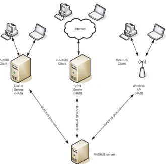
authenticator is operating in pass-through mode. RADIUS [IETF RFC3579] and Diameter [DIAM-EAP] typically provide the AAA protocols with EAP.
This paper will use the terms authenticator, supplicant, and AAA since these are common terms when referring to 802.1x implementations which will be discussed in a future section.
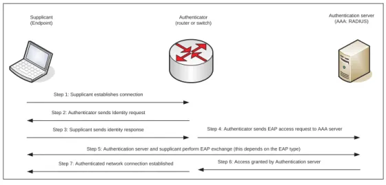
Supplicant (Endpoint) Authenticator (router or switch) Authentication server (AAA: RADIUS)
Step 1: Supplicant establishes connection
Step 2: Authenticator sends Identity request
Step 3: Supplicant sends identity response Step 4: Authenticator sends EAP access request to AAA server
Step 5: Authentication server and supplicant perform EAP exchange (this depends on the EAP type) Step 6: Access granted by Authentication server Step 7: Authenticated network connection established
Figure 4-9 - EAP exchange (Source: Aboba et al.)
Figure 4-9 shows a typical EAP exchange. EAP exchanges occur between a supplicant, an authenticator, and an AAA (authentication) server. A typical exchange involves the exchange of request and response packets.
1. The supplicant establishes communications with the authenticator.
2. The authenticator sends a request to the supplicant. This may be a request for the supplicant’s identity but it is not required.
3. The supplicant responds to the request packet with requested information. 4. The authenticator sends an EAP access request to the authentication server.
5. The supplicant and authentication server exchange EAP request / response (depends on the type of EAP type being used) until the authentication server can authenticate the supplicant.
6. If the authentication is successful, an EAP success response is returned to authenticator; otherwise, an EAP failure packet is returned.
7. Authenticator establishes network connection with supplicant.
Because EAP is essentially a peer-to-peer protocol, mutual authentication can also occur with simultaneous conversations (Hardjono and Dondeti, 2005; Aboba et al., 2004).