PRES
SURE TRANSDUCERS
Gems Transducers Deliver Top
Performance and Value Under Pressure!
Excellent Repeatability, Reliability
Sensing Ranges from Vacuum to 25,000 psi (-1 to 1,600 bar)
Broad Range of Sensing Technologies:
• Chemical Vapor Deposition
• Sputtered Thin Film
• Capacitance
• MMS
When your applications require exceptional pressure sensing
performance and long-life reliability, look to Gems to deliver. From
vacuum to 25,000 psig (-1 to 1,600 bar), we’ve got you covered
with industry’s largest selection and best choice of technologies. Our
capacitance type sensors are ideal for high volume use; sputtered thin
film types are the most precise pressure sensors you can buy, and our
other types satisfy all requirements in between.
Typical Applications
• Off Highway Vehicles — Load Weighing Systems and Load Moment Indicating • Natural Gas Equipment — Compressors and Dispensing Equipment
• Semiconductor Processing — Wafer Manufacturing • Power Plants — Piping Steam Pressures
• Refrigeration — Compressors and Lube Oil Pressure Equipment • Robotics — Factory Automated Equipment
• Test & Measurement — Dynamometers, Medical Instrumentation, Wind Tunnels • Barometrics — Altimeter Certification, Weather Stations
• HVAC — Compressors, Filter Monitoring, Energy Management • Transportation — Breaking, Compressors, Lifts, Air Conditioning
Psibar
®CVD Type
Chemical Vapor Deposition manufacturing methods bond a polysilicon layer to a stainless steel diaphragm at the molecular level to produce a sensor with superior long term drift performance. Common batch processing semiconductor manufacturing methods are used to create a polysilicon strain guage bridge with terrific performance at a very reasonable price. CVD construction offers excellent price/perfomance and is the most popular sensor for OEM applications.
Sputtered Thin Film Type
Sputtered film deposition creates transducers with maximum combined linearity, hysteresis and repeatability. Accuracy is as high as 0.08% full scale with long term drift as low as 0.06% full scale per year. Phenomenal performance for critical instruments — Gems sputtered thin film transducers are the jewels of the pressure sensing industry.
Capacitance Type
Gems manufactures capacitance type pressure sensors for a wide range of high volume OEM and specialty applications. Detecting the capacitance change between two surfaces allows Gems transducers to sense extremely low pressure and vacuum levels. Robust construction allows these units to be used in a wide variety of applications. Coupled with an ASIC, these units provide good price/performance in a host of packaging styles.
MMS Type
Contents
Page Start
Psibar
®CVD Types
...H-3
Psibar® CVD Types
Sputtered Thin Film Types
Capacitance Types
PRES
SURE TRANSDUCERS
Purpose Pressure Range (Full Scale, Typ.)Accuracy
Long Term Drift (Full Scale/Year) Thermal Error per °F relative to Room Temperature (Full Scale
Typ.) Temperatures*Operating Ratiometric Millivolt Voltage Output Current Output Gauge Absolute Vacuum Diff. Pressure Submersible Sanitar
y
Semiconductor Digital Output
Sensor Technology Type Gems Series Number General/ OEM Vacuum to 6000 psig (-1 to 414 bar) 0.25% (0.15% optional) 0.20% 0.015% -40°F to +260°F (-40°C to +125°C)
• • • • • •
•
Strain Gauge (CVD) 2200/2600 0.50% 0.20% 0.020%• • •
•
Strain Gauge (CVD) 1200/1600 Vacuum to 10,000 psig (-1 to 690 bar) 0.25% 0.50% ±0.035% (-40°C to +85°C)-40°F to +185°F• • •
•
Capacitance 809 2 to 10,000 psig(0 to 690 bar) <25psi: 0.25% >25psi: 0.13% 0.50% <25psi: 0.035% >25psi: 0.025% (-40°C to +125°C)-40°F to +260°F
• • •
Capacitance 85610 in. WC to 150 in. WC
(25 to 350 mbar) 0.20% 0.25% 0.028% (-40°C to +100°C)-40°F to +212°F
• • •
•
Capacitance 5000High Accuracy
2 to 6,000 psi
(0.5 to 400 bar) 0.15% 0.15% 0.010% (-30°C to +100°C)-22°F to +212°F
• • •
•
Strain Gauge (CVD) 67002 to 10,000 psig
(0.2 to 690 bar) 0.10% 0.10% 0.008% (-30°C to +100°C)-22°F to +212°F
• • •
•
Strain Gauge (Sputtered) 470015 to 10,000 psig
(1 to 690 bar) 0.08% 0.06% 0.006% (-54°C to +135°C)-65°F to +275°F
•
• • •
•
Strain Gauge (Sputtered) 40000 to 30,000 psig
(0 to 2,200 bar) 0.25% 0.2% 0.83% (-40°C to +125°C)-40°F to +257°F
•
• • •
Strain Gauge (Sputtered) 3100/3200High Temperature & Accuracy
15 to 6,000 psig
(1 to 400 bar) 0.10% 0.06% 0.006% (-54°C to +230°C)-65°F to +450°F
•
• •
Strain Gauge (Sputtered)4000 High Temp Specialty 600 to 1,100 hPa/mb 800 to 1,100 hPa/mb 0 to 20 psia 0.25% 0.25%/ 6 mos. 0.033% (-18°C to +80°C)0°F to +175°F
•
•
•
•
Capacitance 876 0.25 to 100 in. WC (Unidirectional) 0.1 to 50 in. WC (Bidirectional) 1.00% 0.50% 0.066% (-18°C to +65°C)0°F to +150°F• • •
•
•
Capacitance 865 1 to 100 psid (0.0 to 7 bar) 0.25% 0.50% 0.040% (-18°C to +80°C)0°F to +175°F• • •
•
Capacitance 830 Vacuum to 1,000 (-1 to 69 bar) 0.20% 0.50% 0.040% (-40°C to +125°C)-40°F to +260°F• •
•
•
Capacitance 890 5 to 260 psig(0.35 to 18 bar) 0.25% 0.20% 0.012% (-40°C to +80°C)-40°F to +180°F
• • • •
•
Strain Gauge (MMS) 2400500 to 10,000 psig
(0 to 690 bar) 0.10% 0.05% 0.20% (-40°C to +85°C)-40°F to +185°F
•
Strain Gauge (Sputtered) 9000PRES
SURE TRANSDUCERS
Temperature Range Size A Number of Cooling Fins
302ºF (150°C) 0.87 (22) 2 572ºF (300°C) 1.34 (34) 3
A
Intrinsically Safe units length increased by 1.06˝ (27 mm).
1700 Series-Hygienic Pressure
Transmitters
Pressure Ranges from 100 Millibar to 40 Bar
Sanitary or G1 Process Connections
Voltage and Current Output Models
Temperature Cooling Options Available for 302ºF or 572ºF (150°C
or 300°C) Operation
The 1700 series features a stainless steel diaphragm with various process
connections suitable for dairy and pharmaceutical applications. The 1700 is suitable for both static and dynamic pressure measurement in the ranges from 100 millibar to 40 bar and is available with a choice of electrical outputs and connecctions.
Specifications
Input
Pressure Range 0 to 600 psi (0 to 40 bar) Gauge and Absolute
Proof Pressure >2 x Full Scale
Burst Pressure >2 x Full Scale
Fatigue Life Designed for more than 100 million cycles
Performance
Long Term Drift ±0.2% span/annum
Accuracy 0.25%
Thermal Error Over 1% (0°C to 70°C), 2% for 100, 250, and 400 millibar ranges
Compensated Temperature (0°C to 50°C)
Operating Temperatures -13°F to +185°F (-25°C to +85°C) -13°F to +257°F (-25°C to +125°C) media
Zero Tolerance 1% of span
Span Tolerance 1% of span
Mechanical Configuration
Pressure Port see ordering chart
Wetted Parts 316 S/S: Seals Viton® (G1 thread only)
Electrical Connection see ordering chart
Enclosure IP65 = G (with connector fitted) IP67 = E & F
Fill Fluid Silicon oil or food grade
Vibration 10g rms, 20 - 2000Hz
Acceleration 10g
Shock 100g 11ms
Approvals CE, EXII 1G, E Exia IIC T4
Weight 175gm
Voltage Output Units
Output see ordering chart
Supply Voltage (Vs) 12 to 36Vdc
Supply Voltage Sensitivity 0.005% FS/Volt Min. Load Resistance 10Kohm
Current Consumption 15 mA max
Current Output Units
Output 4 - 20mA 2 wire
Supply Voltage (Vs) 12 to 36Vdc (IS units 14 - 28 volts)
Supply Voltage Sensitivity 0.005% FS/Volt Max. Loop Resistance (Vs-12) x 50 ohms
Dimensions inch (mm)
EMC Specifications
Emissions & Immunity according to EN61326.
3.17 (80.5) 1.73 (44.0) A/F Hex Ø1.04 (26.5) 2.77 (70.5) (54.5)2.14 Ø1.04 (26.5) Ø1.04 (26.5) 0.75 (19.0) Flush Diaphragm Ø1.06 (27.0) Flush Diaphragm DN 1 Ø1.06 (24.0) DN 1-1/2 Ø1.26 (32.0) Flush Diaphragm DIN 2 Ø1.77 (45.0) Flush Diaphragm Ø1.06 (24.0) DN25 - Ø1.73 (44.0) DN40 - Ø2.20 (56.0) DN50 - Ø2.7 (68.5) Ø2.52 (64.0) Fixed Plug to DIN 43650 M12 x 1 Clamp Version Cooling Element
Clamp Version Dairy Pipe Version G1˝ Thread
Version
PRES
SURE TRANSDUCERS
Electrical Connection Code
2-Wire System 3-Wire System
Supply + Supply – Ground Supply + Supply – Signal + Ground
E M12 x 1 (4-pin) 1 2 4 1 2 3 4
F Cable WH BR DRAIN WH BR G DRAIN
G “DIN 43650” 1 2 GROUND 1 2 3 GROUND
How to Order
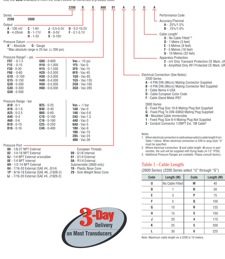
Use the bold characters from the chart below to construct a product code
Series 1700 Output B - 4-20mA S - 0-10V Datum G - Gauge A - Absolute Pressure Range
N10 - 0.10 bar N25 - 0.25 bar N40 - 0.40 bar N60 - 0.60 bar
A10 - 1 bar A16 - 1.6 bar A40 - 4 bar A60 - 6 bar
B10 - 10 bar B16 - 16 bar B25 - 25 bar B40 - 40 bar
1A0 - -1 to 0 bar Pressure Connection
F3 - G1˝ DIN 38521 F4 - G1 1/2˝ DIN 3852
C1 - Clamp DN 1˝ 3 C2 - Clamp DN 1 1/2˝ 2
C3 - Clamp DN 2˝ 1 D1 - Dairy Pipe DN 252
D2 - Dairy Pipe DN 4024 D3 - Dairy Pipe DN 5014
Filling Liquid 1 - Silicon Oil
2 - Food compatible, Mobil DTEFM32 C - Halocarbon
Special Versions
0 - Standard
1 - Cooling Element up to 150°C5
2 - Cooling Element up to 300°C5
3 - Dairy Pipe Mating Nut45 Accuracy
2 - ±0.25% (>0.4 bar)
Approvals 3 - CE Mark
G - Intrinsic Safety Ex II 1G, EEx ia IIC T4 (-20<Ta+60°C) Electrical Connection
E - M12 x 1 (4 Pin)
F - Cable Gland including 2m Cable G - Fixed Plug to DIN 43650 Diaphragm Material 0 - Stainless Steel Seal
0 - No Seal
1 - Viton® (Supplied with G1˝
Pressure Port only)
1700 B G A10 C2 2 1 0 G 3 2 0
Electrical Connections
Cable Legend: WH = White BR = Brown G = Green Notes:1. Not available for ranges ≤250mb.
2. Not available for ranges ≤400mb.
3. Not available for ranges ≤600mb.
4. For Dairy Pipe Mating Nut.
5. Please state media temperature (max 85°C) and mounting orientation.
PRES
SURE TRANSDUCERS
Dim A Dim B Dim C Dim D
G1/2˝ Thread (76.5)3.01 (15.0)0.59 (27.0)1.06 (18.0)0.71 G3/4˝ Thread (78.5)3.09 (16.0)0.63 (34.0)1.34 (22.0)0.87 G1˝ Thread (80.5)3.17 (19.0)0.75 (44.0)1.73 (28.0)1.10
1701 Series-Flush Diaphragm Pressure
Transmitters
Stanless Steel Wetted Parts with Flush Diaphragm
G1/2, G3/4 or G1 Threads and Sanitary
Voltage and Current Output Models
The 1701 series features a stainless steel flush diaphragm on a threaded process connection making it ideal for slurries, suspended solids in liquids and viscous liquids where recessed diaphragms could become blocked. The 1701 is suitable for both static and dynamic pressure measurement in the ranges from 15 PSI to 5802 PSI (1 bar to 400 bar) and is available with a choice of electrical outputs and connections.
Specifications
Input
Pressure Range 0 to 6000 psi (0 to 400 bar) Gauge 0 to 370 psi (0 to 25 bar) Absolute
Proof Pressure >2 x Full Scale (1.5 x for 400 bar)
Burst Pressure >2 x Full Scale
Fatigue Life Designed for more than 100 million cycles
Performance
Long Term Drift ±0.2% span/annum
Accuracy 0.25%
Thermal Error 2% max
Compensated Temperature -13°F to +185°F (-25°C to +85°C) Operating Temperatures -13°F to +185°F (-25°C to +85°C) -13°F to +257°F (-25°C to +125°C) media
Zero Tolerance 1% of span
Span Tolerance 1% of span
Mechanical Configuration
Pressure Port see ordering chart
Wetted Parts 316 S/S: Seals <100 bar Viton® >100 bar Nitrite
Electrical Connection see ordering chart
Enclosure IP65 = G (with connector fitted) IP67 = E & F
Fill Fluid Silicon oil or food grade
Vibration 10g rms, 20 - 2000Hz
Acceleration 10g
Shock 100g 11ms
Approvals CE, EXII 1G, E Exia II CT4
Weight 225gm
Voltage Output Units
Output see ordering chart
Supply Voltage (Vs) 14 to 36Vdc
Supply Voltage Sensitivity 0.005% FS/Volt Min. Load Resistance 10Kohm
Current Consumption 15 mA max
Current Output Units
Output 4 - 20mA 2 wire
Supply Voltage (Vs) 12 to 36Vdc (IS units 14 - 28 volts)
Supply Voltage Sensitivity 0.005% FS/Volt Max. Loop Resistance (Vs-12) x 50 ohms
Dimensions inch (mm)
EMC Specifications
Emissions & Immunity according to EN61326.
1.5 (38.1) to Disconnect Dimension A Dimension B Dimension C A/F Hex Dimension D Flush Diaphragm MECHANICAL CONNECTION Inch Thread
Fixed Plug to DIN
PRES
SURE TRANSDUCERS
Electrical Connection Code
2-Wire System 3-Wire System
Supply + Supply – Ground Supply + Supply – Signal + Ground
E M12 x 1 (4-pin) 1 2 4 1 2 3 4
F Cable WH BR DRAIN WH BR G DRAIN
G “DIN 43650” 1 2 GROUND 1 2 3 GROUND
How to Order
Use the bold characters from the chart below to construct a product code
Series 1701 Output B - 4-20mA S - 0-10V Datum G - Gauge A - Absolute - 1 to 25 bar Pressure Range
A10 - 1 bar A16 - 1.6 bar A25 - 2.5 bar A40 - 4 bar
A60 - 6 bar B10 - 10 bar B16 - 16 bar B25 - 25 bar
B40 - 40 bar B60 - 60 bar C10 - 100 bar C16 - 160 bar
C25 - 250 bar C40 - 400 bar 1A0 - -1 to 0 bar
Pressure Connection
F1 - G1/2˝ DIN 38521 F2 - G3/4˝ DIN 3852
F3 - G1˝ DIN 3852 Filling Liquid 1 - Silicon Oil
2 - Food compatible, Mobil DTEFM32
Special Versions 0 - Standard Accuracy 2 - ±0.25% Approvals 3 - CE Mark G - Intrinsic Safety Ex II 1G, EEx ia IIC T4 (-20<Ta+60°C) Electrical Connection
E - M12 x 1 (4 Pin)
F - Cable Gland including 2m Cable G - Fixed Plug to DIN 43650 Diaphragm Material 0 - Stainless Steel Seal 1 - Viton® <100 bar 2 - Nitrile®≥100 bar 1701 B G A10 F2 1 1 0 G 3 2 0
Electrical Connections
Cable Legend: WH = White BR = Brown G = Green Notes:PRES
SURE TRANSDUCERS
1702 Series-Fixed Range Low Pressure
Transmitters
Pressure Ranges from 40 millibar to 1 Bar
316 S/S Diaphragm
Voltage and Current Output Models
Choice of Enclosures and Pressure Fittings
The Gems 1702 low range pressure transmitter is ideal for pneumatics, process control and chemical processes. Featuring a 316 S/S diaphragm and Viton® o-ring
the 1702 is compatible with many corrosive medias. A choice of process connections makes the units suitable for direct pipe mounting whilst optional eletrical outputs and connections allow interfacing with most systems.
Specifications
Input
Pressure Range 100 mbar to 1 bG, 100 mbar to 1bA
Proof Pressure >2 x Full Scale
Burst Pressure >2 x Full Scale
Fatigue Life Designed for more than 100 million cycles
Performance
Long Term Drift ±0.1% span/annum
Accuracy 0.25%
Thermal Error Over 1% (0°C to 70°C) - 1 bar, 2% for 100 mbar to 400 mbar ranges
Compensated Temperature (0°C to 50°C)
Operating Temperatures -13°F to +185°F (-25°C to +85°C) -13°F to +257°F (-25°C to +125°C) media
Zero Tolerance 1% of span
Span Tolerance 1% of span
Mechanical Configuration
Pressure Port see ordering chart
Wetted Parts 316 S/S, Viton®
Electrical Connection see ordering chart
Enclosure IP65 = G (with connector fitted) IP67 = E & F
Vibration 10g rms, 20 - 2000Hz
Acceleration 10g
Shock 100g 11ms
Weight 140gm
Voltage Output Units
Output see ordering chart
Supply Voltage (Vs) 12 to 36Vdc
Supply Voltage Sensitivity 0.005% FS/Volt Min. Load Resistance 10Kohm
Current Consumption 7 mA max
Current Output Units
Output 4 - 20mA 2 wire
Supply Voltage (Vs) 12 to 36Vdc
Supply Voltage Sensitivity 0.005% FS/Volt Max. Loop Resistance (Vs-12) x 50 ohms
Dimensions inch (mm)
1.5 (38.1) 1.85 (47.0) 0.47 (12.0) (14.0)0.55 (14.0)0.55 0.90 (23.0) Ø1.04 (26.5) Ø1.06 (27.0) A/F Hex Fixed Plug to DIN 43650(1702X-G3) M12 x 1 (1702X-E3) 2m Cable (1702X-E3)
G1/4˝ DIN
3852 Thread NPT Thread1/4˝ - 18 3852 ThreadG1/2˝ DIN
Semi Flush Diaphragm G1/2˝ Manometer Thread to Disconnect
PRES
SURE TRANSDUCERS
Electrical Connection Code
2-Wire System 3-Wire System
Supply + Supply – Ground Supply + Supply – Signal + Ground
E M12 x 1 (4-pin) 1 2 4 1 2 3 4
F Cable WH BR DRAIN WH BR G DRAIN
G “DIN 43650” 1 2 GROUND 1 2 3 GROUND
How to Order
Use the bold characters from the chart below to construct a product code
Series 1702 Output B - 4-20mA S - 0-10V Datum G - Gauge A - Absolute ≥ 100 mbar Pressure Range
N10 - 100 mbar N25 - 250 mbar N40 - 400 mbar N60 - 600 mbar Pressure Connection 01 - G1/4˝ EXT 02 - 1/4˝-18 NPT EXT 03 - G1/2˝ Manometer FO - G1/5˝ Semi-Flush Special Versions 0 - Standard Accuracy 2 - 0.25% Approvals 3 - CE Mark Electrical Connection E - M12 x 1 (4 Pin)
F - Cable Gland including 2m Cable G - Fixed Plug to DIN 43650 Diaphragm Material 0 - Stainless Steel Seal 1 - Viton® 1702 B G A10 02 0 1 0 G 3 2 0
Electrical Connections
Cable Legend: WH = White BR = Brown G = GreenPRES
SURE TRANSDUCERS
II 1G
II 1G
22IC Series / 26IC Series –
CSA Intrinsically Safe
Industrial Pressure Transducers
Ex II 1G; Ex ia IIC T4 Ga
Vacuum to 6,000 PSI (400 bar); Absolute or Gauge
Voltage and 2 Wire 4-20mA Output Models
All Stainless Steel Wetted Parts
Certified to the latest harmonized European standard (ATEX) the 22IC and 26IC Intrinsically safe pressure transmitters are designed to withstand the rigours of the most difficult applications with an all stainless steel construction, free from seals or oil barriers.
Incorporating Gems CVD Sensors and ASIC technology the 22IC and 26IC offer long term reliability, excellent performance and long term stability ensuring long service life without routine maintenance.
Available with a wide choice of pressure fittings units can be supplied to IP65 or fully immersible to IP68 200mWG and a variety of electrical connectors.
Specifications
Input
Pressure Range Vacuum to 6000 psi G (400 bar) 0-363 psi Absolute (0-25 bar)
Proof Pressure 2 x Full Scale (FS) (1.5 x FS for ≥ 5000 psi, 400 bar)
Burst Pressure >35 x FS <= 100 psi (6 bar); >20 x FS <= 1000 psi (60 bar); >5 x FS <= 6000 psi (400 bar)
Fatigue Life Designed for more than 100 million FS cycles
Performance
Long Term Drift 0.2% FS/year (non-cumulative)
Accuracy 0.25% FS typical (optional 0.15% FS)
Thermal Error 1.5% FS typical (optional 1% FS)
Compensated Temperatures -5°F to +180°F (-20°C to +80°C)
Operating Temperatures -40°F to +260°F (-40°C to +125°C) for elec. codes A, B, C -5°F to +180°F (-20°C to +80°C) for elec. code G -5°F to +125°F (-20°C to +50°C) for elec. codes F, M, 3
Zero Tolerance 1% of span
Span Tolerance 1% of span
Mechanical Configuration
Pressure Port See ordering chart
Wetted Parts 17-4 PH Stainless Steel
Electrical Connection See ordering chart
Enclosure 316 ss, 17-4 PH ss
IP65 for elec. codes A, B, C, G (with connector fitted) 3 IP67 for elec. code “F”
IP68 for elec. codes M
Vibration 35g peak sinusoidal, 5 to 2000 Hz
Acceleration 100g steady acceleration in any direction 0.032% FS/g for 15 psi (1 bar) range decreasing logarithmically to 0.0007% FS/g for 6000 psi (400 bar) range.
Shock Withstands free fall to IEC 68-2-32 procedure 1
Approvals Ex II 1G; Ex ia IIC T4 Ga,
-4°F ≤ Ta ≤ +167°F (-20°C ≤ Ta ≤ +75°C)
Weight Approx. 3.5 ounces (100 grams) (additional cable; 75 g/m)
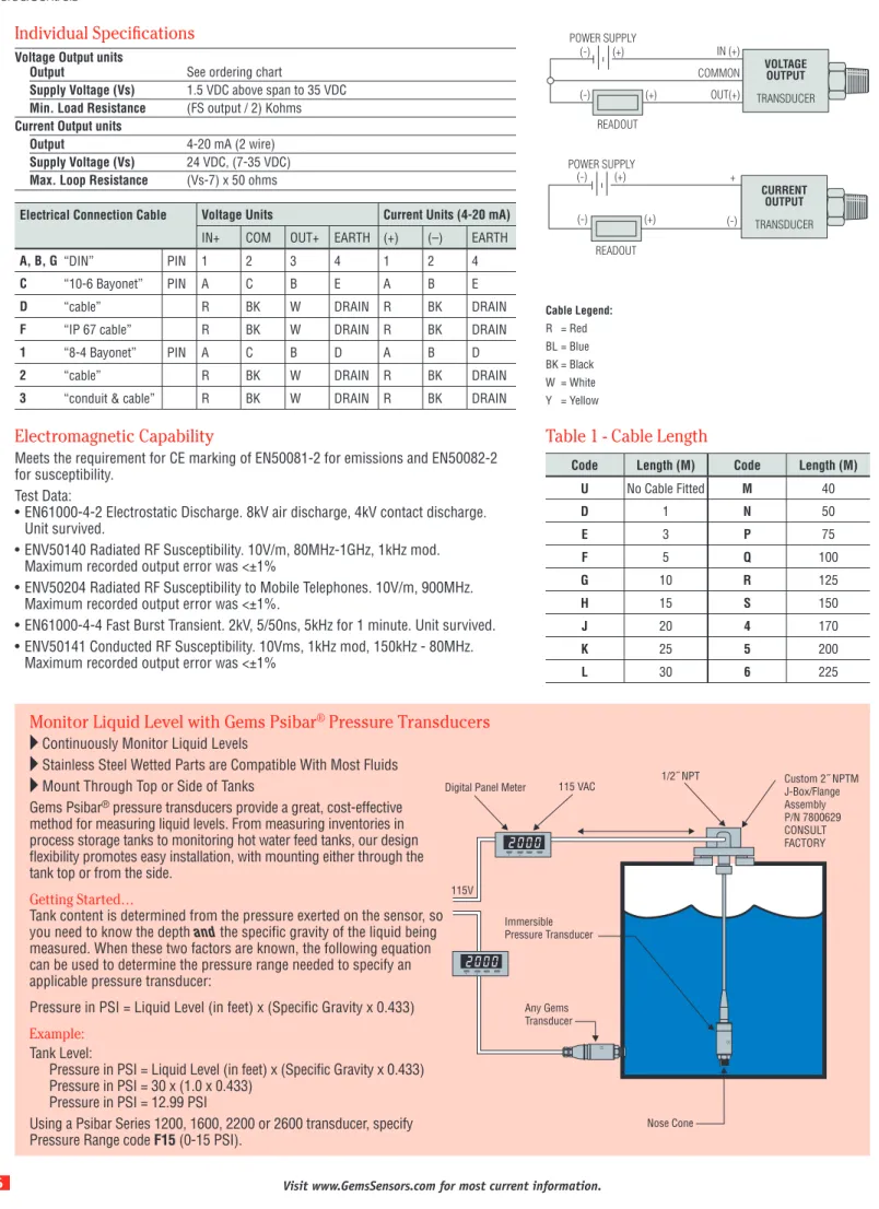
Individual Specifications
Voltage Output units
Output see ordering chart
Supply Voltage (Vs) 1.5 Vdc above FS output
to 25.5 Vdc
Supply Voltage Sensitivity 0.01% FS/Volt Min. Load Resistance (FS output / 2) Kohms
Current Consumption approx 6 mA at 7.5V output
Current Output units
Output 4-20 mA (2 wire)
Supply Voltage (Vs) 24 Vdc, (7-35 Vdc) above 212°F (100°C) supply
Series 22IC
PRES
SURE TRANSDUCERS
26IC Series
Code B Code A Code F Code D or 2 10-6 Code C Code G Code 3 Code T Code M 8-4 Code 1 1.30 (33) 1.70 (43) 1.22 (31) 1.37 (35.0) 2.76 (70.1) 0.87 (22) 3.74 (95) 1/2˝ NPT 2.43 (61.60)MAX 2.09 (53.2)MAX 0.75 (19) 0.67 (17) Code 04 Code 05 Code 19 Maximum diameter 1.07˝ (27.3 mm) Maximum diameter 1.07˝ (27.3 mm)Mini 4 Pin - No Connector
Mini 4 Pin - With Connector
IP67 Cable (Waterproof)
IP65 or NEMA4 Cable
10-6 or 8-4 Mil-C Connector
mV Gauge Amplified Gauge
mV Gauge Amplified Gauge
Large DIN 43650 Plug
0.79 (20) Code 02 1/4 - 1/8 NPT 0.67 (17) 0.79 (20) Code 0A R 1/4 0.66 (17) G 1/4 External G 1/2 Manometer 7/16-20 UNF-2A G 1/4 Soft Seal Code 09 G 1/8 Internal Code 08 1/8-27 NPT
Nose Cone - Black Acetal Conduit Connector with Cable
Conduit Connector with Flying Leads
Moulded, Immersible Cable
2.65 (68) 0.74 (19) Code 00 G 1/4 Internal 0.87 (22.0) Code 01 Code 03 0.75
Dimensions
22IC Series
PRES
SURE TRANSDUCERS
How to Order
Use the bold characters from the chart below to construct a product code Series 22IC 26IC Output B - 4-20mA C - 1-6V J - 0.5-5.5V D - 1-11V R - 0-5V H - 1-5V S - 0-10V Pressure Datum A - Absolute G - Gauge
Pressure Range1 – psi
F15 - 0-15 G60 - 0-600 Vac = -15 psi F30 - 0-30 H10 - 0-1,000 1F5 - Vac-0 F60 - 0-60 H15 - 0-1,500 3F0 - Vac-15 G10 - 0-100 H20 - 0-2,000 6F0 - Vac-45 G15 - 0-150 H30 - 0-3,000 1G0 - Vac-85 G20 - 0-200 H40 - 0-4,000 1G5 - Vac-135 G30 - 0-300 H50 - 0-5,000 2G0 - Vac-185 G50 - 0-500 H60 - 0-6,000 3G0 - Vac-285
Pressure Range1 – bar
A10 - 0-1 B25 - 0-25 Vac = -1 bar
A16 - 0-1.6 B40 - 0-40 1A0 - Vac-0
A25 - 0-2.5 B60 - 0-60 1A6 - Vac-0.6
A40 - 0-4 C10 - 0-100 2A5 - Vac-1.5
A60 - 0-6 C16 - 0-160 4A0 - Vac-3
B10 - 0-10 C25 - 0-250 6A0 - Vac-5 B16 - 0-16 C40 - 0-400 1B0 - Vac-9 1B6 - Vac-15 2B5 - Vac-24 4B0 - Vac-39 Pressure Port2 01 - G1/4 External 08 - 1/8-27 NPT External 02 - 1/4-18 NPT External 09 - G1/8 Internal 03 - G1/2 Manometer 00 - G1/4 Internal
04 - 7/16-20 UNF to SAE J514 0A - R1/4 External
05 - G1/4 Ext. Soft Seal 19 - Nose Cone (26IC Only)
Electrical Connection 22IC Series
A - Industrial DIN Mating Connector Supplied B - Industrial DIN Mating Connector Not Supplied F - Cable Gland Metal IP67
26IC Series
C - Fixed Plug Size 10-6 Mating Plug Not Supplied G - Fixed Plug To DIN 43650 Mating Plug Supplied M - Immersible Max. depth 656 feet (200 meters)
1 - Fixed Plug Size 8-4 Mating Plug Not Supplied
3 - Conduit Connector 1/2NPT Ext. 1M Cable
22IC B G A60 01 A B U A Performance Code Accuracy/Thermal A - .25%/1.5% B - .15%/1.0% Cable Length3 U - No Cable Fitted D - 3 feet (1 Meter) E - 9 feet (3 Meters) F - 16 feet (5 Meters) G - 32 feet (10 Meters) H - 49 feet (15 Meters) J - 65 feet (20 Meters) K - 82 feet (25 Meters) L - 98 feet (30 Meters) M - 131 feet (40 Meters) N - 164 feet (50 Meters) P - 246 feet (75 Meters) Q - 328 feet (100 Meters) R - 410 feet (125 Meters) S - 492 feet (150 Meters) Apparatus Protection
B - Intrinsically safe, zener barrier, Gauge only G - Intrinsically safe, galvanic barrier Gauge or Absolute
Ex ia IIC T4 Ga, -4°F ≤ Ta ≤ 167°F (-20°C ≤ Ta ≤ +75°C)
Notes:
1. Additional intermediate ranges available. Please consult factory. 2. Addition Pressure Ports available. Please consult factory. 3. Max length on 22IC-32 feet (10 Meters).
Connection Code Voltage units Current units (4-20mA)
IN+ COM OUT+ EARTH (+) (–) EARTH
A, B, G Industrial DIN PIN 1 2 3 4 1 2 4
C “10-6 Bayonet” PIN A C B E A B E
D Cable R BK W DRAIN R BK DRAIN
F IP67 cable R BK W DRAIN R BK DRAIN
1 “8-4 Bayonet” PIN A C B D A B D
3 “conduit & cable” R BK W DRAIN R BK DRAIN
M Immersible IP68 to 200m R W Y DRAIN R BL DRAIN
Cable Legend: R = Red BL = Blue BK = Black W = White Y = Yellow II 1G
PRES
SURE TRANSDUCERS
PRES
SURE TRANSDUCERS
2200 Series / 2600 Series –
General Purpose
Industrial Pressure Transducers
Gauge, Absolute, Vacuum and Compound Pressure Models
Available
Submersible, General Purpose and Wash Down Enclosures
High Stability Achieved by CVD Sensing Element
Millivolt, Voltage and Current Output Models
The 2200 series features stability and accuracy in a variety of enclosure options. The 2600 series extends the packaging options via an all welded stainless steel back end for demanding submersible and industrial applications. The 2200 and the 2600 feature proven CVD sensing technology, an ASIC (amplified units), and modular packaging to provide a sensor line that can easily accommodate specials while not sacrificing high performance.
Specifications
Input
Pressure Range Vacuum to 6000 psi (400 bar)
Proof Pressure 2 x Full Scale (FS) (1.5 x Fs for 400 bar, ≥ 5000 psi)
Burst Pressure >35 x FS <= 100 psi (6 bar); >20 x FS >= 1000 psi (60 bar); >5 x FS <= 6000 psi (400 bar)
Fatigue Life Designed for more than 100 million FS cycles
Performance
Long Term Drift 0.2% FS/year (non-cumulative)
Accuracy 0.25 % FS typical (optional 0.15% FS)
Thermal Error 1.5% FS typical (optional 1% FS)
Compensated Temperatures -5°F to +180°F (-20°C to +80°C)
Operating Temperatures -40°F to +260°F (-40°C to +125°C) for elec. codes A, B, C, 1 -5°F to +180°F (-20°C to +80°C) for elec. codes 2, D, G, 3 -5°F to +125°F (-20°C to +50°C) for elec. codes F,M, P Amplified units >100°C maximum 24 VDC supply
Zero Tolerance 1% of span
Span Tolerance 1% of span
Response Time 0.5 ms
Mechanical Configuration
Pressure Port See ordering chart
Wetted Parts 17-4 PH Stainless Steel
Electrical Connection See ordering chart
Enclosure 316 ss, 17-4 PH ss
IP65 NEMA 4 for elec. codes A, B, C, D, G,1, 2, 3 IP67 for elec. code “F”
IP68 for elec. codes M, (max depth 200 meters H2O) IP30 for elec. code “3” with flying leads
Vibration 70g, peak to peak sinusoidal, 5 to 2000 Hz (Random Vibration: 20 to 2000 Hz @ 20g Peak per MIL-STD.-810E Method 514.4)
Acceleration 100g steady acceleration in any direction 0.032% FS/g for 15 psi (1 bar) range decreasing logarithmically to 0.0007% FS/g for 6000 psi (400 bar) range.
Shock 20g, 11 ms, per MIL-STD.-810E Method 516.4 Procedure I
Approvals CE, UR (22IC, 26IC, 22CS, 26CS)
Weight Approx. 100 grams (additional cable; 75 g/m)
Series 2200
PRES
SURE TRANSDUCERS
Connection Code mV units Voltage units Current units (4-20mA)
IN+ OUT+ OUT- IN- IN+ COM OUT+ EARTH (+) (–) EARTH
A, B, G “DIN” PIN 1 2 3 E 1 2 3 4 1 2 4
C “10-6 Bayonet” PIN A B C D A C B E A B E
D “cable” R Y BL G R BK W DRAIN R BK DRAIN
F “IP 67 cable” R Y BL G R BK W DRAIN R BK DRAIN
M “Immersible” R Y BL W R W Y DRAIN R BL DRAIN
1 “8-4 Bayonet” PIN A B C D A C B D A B D
2 “cable” R W G BK R BK W DRAIN R BK DRAIN
3 “conduit & cable” R W G BK R BK W DRAIN R BK DRAIN
VOLTAGE OUTPUT TRANSDUCER POWER SUPPLY READOUT IN (+) (-) (+) COMMON OUT(+) (-) (+) MILLIVOLT OUTPUT TRANSDUCER POWER SUPPLY READOUT IN (+) IN (-) (-) (+) OUT(-) OUT(+) (-) (+)
Individual Specifications
Millivolt Output units
Output 100 mV (10 mv/v)
Supply Voltage (Vs) 10 VDC (15 VDC max.) Regulated
Bridge resistance 2600-6000 ohms
Voltage Output units
Output see ordering chart
Supply Voltage (Vs) 1.5 VDC above span to 35 VDC @ 6 mA
Supply Voltage Sensitivity 0.01% FS/Volt Min. Load Resistance (FS output / 2) Kohms
Current Consumption approx 6 mA at 7.5V output
Current Output units
Output 4-20 mA (2 wire)
Supply Voltage (Vs) 24 VDC, (7-35 VDC)
Supply Voltage Sensitivity 0.01% FS/Volt Max. Loop Resistance (Vs-7) x 50 ohms
Electromagnetic Capability
Meets the requirement for CE marking of EN50081-2 for emissions and EN50082-2 for susceptibility. Test Data:
• EN61000-4-2 Electrostatic Discharge. 8kV air discharge, 4kV contact discharge. Unit survived. • ENV50140 Radiated RF Susceptibility. 10V/m,
80MHz-1GHz, 1kHz mod. Maximum recorded output error was <±1%
• ENV50204 Radiated RF Susceptibility to Mobile Telephones. 10V/m, 900MHz. Maximum recorded output error was <±1%.
• EN61000-4-4 Fast Burst Transient. 2kV, 5/50ns, 5kHz for 1 minute. Unit survived.
• ENV50141 Conducted RF Susceptibility. 10Vms, 1kHz mod, 150kHz - 80MHz. Maximum recorded output error was <±1% Cable Legend: R = Red BL = Blue BK = Black W = White Y = Yellow
PRES
SURE TRANSDUCERS
Nose Cone Sink Weight
2600 Series
Code B Code A Code F Code D or 2 10-6 Code C Code G Code 3 Code 3 with length “U”Code M 8-4 Code 1 1.30 33 43 1.70 1.70/43 1.37 35.0 2.76 70.1 0.87 22 0.90 23 1/2˝ NPT 1/2˝ NPT 2.43 61.60MAX 2.48 65.7MAX 2.09 53.2MAX 0.75 19 0.67 17 2.54 64.4MAX Code 04 Code 1P Code 19 Maximum diameter 1.07" (27.3 mm) Maximum diameter 1.07" (27.3 mm)
Mini 4 Pin - No Connector
Mini 4 Pin - With Connector
IP67 Cable (Waterproof)
IP65 or NEMA4 Cable
10-6 or 8-4 Mil-C Connector
mV Gauge/Absolute Amplified Gauge mV Gauge/Absolute
Amplified Gauge
Large DIN 43650 Plug
Amplified Absolute Amplified Absolute 0.95 24 Code 0E 1/4-18 NPT Internal 0.67 17 0.79 20 0.75 19 Code 01 G 1/4 External 0.79 20 1/4 - 18 NPT 1/2-14 NPT 7/16-20 UNF-2A 9/16-18 UNF-2A Code 0A R 1/4 Code 09 G 1/8 Internal
Nose Cone - Black Acetal Conduit Connector with Cable
Conduit Connector with Flying Leads
Moulded, Immersible Cable
2.65 68 0.59 15 Code 08 1/8-27 NPT 24 AWG Shielded PVC 24 AWG Shielded PVC 24 AWG Shielded PVC
24 AWG, Vent, Shielded, Polyurethane 1.02 26.0 Code 02 with snubber 1.02 26.02 Code 0Jwith snubber Code 0H 4.67/121
Dimensions
2200 Series
PRES
SURE TRANSDUCERS
Code Length (M) Code Length (M)
U No Cable Fitted M 40 D 1 N 50 E 3 P 75 F 5 Q 100 G 10 R 125 H 15 S 150 J 20 4 170 K 25 5 200 L 30 6 225
Note: Maximum cable length on a 2200 is 10 meters.
3
3
-Day
-Day
Delivery
on Most Transducers
European Threads 09 - G1/8 Internal 01 - G1/4 External 0A - R1/4 External Submersible (2600 only) 19 - Plastic Nose Cone 29 - Sink Weight Nose ConeHow to Order
Use the bold characters from the chart below to construct a product code Series 2200 2600 Output A - 100 mV C - 1-6V J - 0.5-5.5V G - 0.2-10.2V B - 4-20mA D - 1-11V R - 0-5V F - 0.1-5.1V H - 1-5V S - 0-10V Pressure Datum A* - Absolute G - Gauge
*Max absolute range is 25 bar. (≤ 300 psi) Pressure Range3 – psi
F07 - 0-7.5 G60 - 0-600 Vac = -15 psi F15 - 0-15 H10 - 0-1,000 1F5 - Vac-0 F30 - 0-30 H15 - 0-1,500 3F0 - Vac-15 F60 - 0-60 H20 - 0-2,000 6F0 - Vac-45 G10 - 0-100 H30 - 0-3,000 1G0 - Vac-85 G15 - 0-150 H40 - 0-4,000 1G5 - Vac-135 G20 - 0-200 H50 - 0-5,000 2G0 - Vac-185 G30 - 0-300 H60 - 0-6,000 3G0 - Vac-285 G50 - 0-500 Pressure Range - bar
A10 - 0-1 B25 - 0-25 Vac = -1 bar
A16 - 0-1.6 B40 - 0-40 1A0 - Vac-0
A25 - 0-2.5 B60 - 0-60 1A6 - Vac-0.6
A40 - 0-4 C10 - 0-100 2A5 - Vac-1.5
A60 - 0-6 C16 - 0-160 4A0 - Vac-3
B10 - 0-10 C25 - 0-250 6A0 - Vac-5 B16 - 0-16 C40 - 0-400 1B0 - Vac-9 1B6 - Vac-15 2B5 - Vac-24 4B0 - Vac-39 Pressure Port 08 - 1/8-27 NPT External 02 - 1/4-18 NPT External 0J - 1/4 NPT External w/snubber 0E - 1/4 NPT Internal 0H - 1/2-14 NPT External 04 - 7/16-20 External (SAE #4, J514) 1P - 9/16-18 External (SAE #6, J1926-2) IJ - 7/16-20 External (SAE #4, J1926-2)
Electrical Connection (See Notes) 2200 Series
A - 4 PIN DIN (Micro) Mating Connector Supplied B - 4 PIN DIN (Micro) Mating Connector Not Supplied 2 - Cable Nema 4 USA
D - Cable European Color Code F - Cable Gland Metal IP67 2600 Series
C - Fixed Plug Size 10-6 Mating Plug Not Supplied G - Fixed Plug To DIN 43650 Mating Plug Supplied M - Moulded Cable Immersible
1 - Fixed Plug Size 8-4 Mating Plug Not Supplied
3 - Conduit Connector 1/2NPT Ext. 1M Cable2
2200 B G A60 01 A 3 U A Performance Code Accuracy/Thermal A - .25%/1.5% B - .15%/1.0% Cable Length1 U - No Cable Fitted1 2 D - 1 Metre (3 feet) E - 3 Metres (9 feet) F - 5 Metres (16 feet) G - 10 Metres (32 feet) Apparatus Protection
2 - mV Only Transient Protection CE Mark, UR 3 - Amplified Only RFI Protected CE Mark, UR
Notes:
1. When electrical connection is cable please select a cable length from Table 1 below. When electrical connection is DIN or plug style “U” must be specified.
2. Where electrical connection -3 and cable length -U occur in part number, the unit will be supplied with flying leads (4-1/2˝ IP30). 3. Additional Pressure Ranges are available. Please consult factory.
Table 1 - Cable Length
PRES
SURE TRANSDUCERS
22CS Series / 26CS Series –
CSA Intrinsically Safe
Industrial Pressure Transmitters
Ranges from 7.5 to 6000psi (0.5 to 400 bar) and
0-300psi (0-25 bar) Absolute
Voltage and 2 Wire 4-20mA output models
All stainless steel wetted parts
Certified by CSA for Canada and USA, the 22CS and 26CS Series intrinsically safe pressure transmitters are designed to withstand the rigors of the most difficult applications. An all-stainless steel construction, eliminates the need for seals and oil barriers that can deteriorate over time.
Incorporating Gems CVD Sensors and ASIC technology the 22CS and 26CS Series offer long term reliability, excellent performance and long term stability ensuring long service life without routine maintenance.
Available with a wide choice of pressure fittings and electrical connections rated from IP65 to fully immersible (IP68 200m WG).
Specifications
Input
Pressure Range Vacuum to 6000 psi G (400 bar); 300 psi Absolute (0-25 bar)
Proof Pressure 2 x Full Scale (FS)
(1.5 x FS for 400 bar, ≥ 5000 psi)
Burst Pressure >35 x FS ≤ 100 psi (6 bar); >20 x FS ≤ 1000 psi (60 bar); >5 x FS ≤ 6000 psi (400 bar)
Fatigue Life Designed for more than 100 million FS cycles
Performance
Long Term Drift 0.2% FS/year (non-cumulative)
Accuracy 0.25% FS typical (optional 0.15% FS)
Thermal Error 1.5% FS typical (optional 1% FS)
Compensated Temperatures -5°F to +180°F (-20°C to +80°C)
Operating Temperatures -40°F to +260°F (-40°C to +125°C) for elec. codes A, B, C -5°F to +180°F (-20°C to +80°C) for elec. codes G -5°F to +125°F (-20°C to +50°C) for elec. codes F, M, 3
Zero Tolerance 1% of span
Span Tolerance 1% of span
Mechanical Configuration
Pressure Port See ordering chart
Wetted Parts 17-4 PH Stainless Steel
Electrical Connection See ordering chart
Enclosure 316 SS, 17-4 PH SS
IP65 for elec. codes A, B, C, 3 and G (with DIN connector fitted) IP67 for elec. code F
IP68 for elec. codes M
Vibration 35g peak sinusoidal, 5 to 2000 Hz
Acceleration 100g steady acceleration in any direction 0.032% FS/g for 15 psi (1 bar) range decreasing logarithmically to 0.0007% FS/g for 6000 psi (400 bar) range.
Shock Withstands free fall to IEC 68-2-32 procedure 1
Approvals CSA Certified
Class I, Division 1, Groups A, B, C, D Class II, Division 1, Groups E, F, G
Class III
When used in conjunction with a Zener safety barrier
Weight Approx. 3.5 ounces (100 grams) (additional cable; 75 g/m)
Series 22CS
PRES
SURE TRANSDUCERS
Connection Code mA Output Voltage Output
+VE -VE EARTH -VE COMMON EARTH EARTH
22CS A, B 1 2 E 1 2 2 4 2, D, F R BK DRAIN R BK W DRAIN 26CS 1 A B D A B C D C A B E A B C E G 1 3 E 1 2 3 E
3 (Cable) R BK DRAIN R BK W DRAIN
F (Leads) R BK GR R BK W GR
M R BL DRAIN R W Y DRAIN
Electrical Connections
Individual Specifications
Voltage Output units
Output See ordering chart
Supply Voltage (Vs) 1.5 VDC above FS output to 28 VDC
Supply Voltage Sensitivity 0.01% FS/Volt Min. Load Resistance (FS output / 2) Kohms
Current Consumption Approx 6 mA at 7.5V output
Current Output units
Output 4-20 mA (2 wire)
Supply Voltage (Vs) 24 VDC, (7-28 VDC)
Supply Voltage Sensitivity 0.01% FS/Volt Max. Loop Resistance (Vs-7) x 50 ohms
Electromagnetic Capability
Meets the requirement for CE marking of EN50081-2 for emissions and EN50082-2 for susceptibility. Test Data:
• EN61000-4-2 Electrostatic Discharge. 8kV air discharge, 4kV contact discharge. Unit survived. • ENV50140 Radiated RF Susceptibility. 10V/m,
80MHz-1GHz, 1kHz mod. Maximum recorded output error was <±1%
• ENV50204 Radiated RF Susceptibility to Mobile Telephones. 10V/m, 900MHz. Maximum recorded output error was <±1%.
• EN61000-4-4 Fast Burst Transient. 2kV, 5/50ns, 5kHz for 1 minute. Unit survived.
• ENV50141 Conducted RF Susceptibility. 10Vms, 1kHz mod, 150kHz - 80MHz. Maximum recorded output error was <±1% Cable Legend: R = Red BK = Black W = White G = Green BL = Blue Y = Yellow
PRES
SURE TRANSDUCERS
26CS Series
Code B Code A Code F Code D or 2 10-6 Code C Code G Code 3 Code M Code F 8-4 Code 1 1.30 33 3.78 96 1.70 43 1.70 43 1.37 35.0 2.76 70.1 0.87 22 1/2˝ NPT 2.43 61.60MAX 2.48 65.7MAX 2.09 53.2MAX 0.75 19 0.67 17 0.59 15 2.54 64.4MAX Code 04 Code 05 Maximum diameter 1.07" (27.3 mm) Maximum diameter 1.07" (27.3 mm)Industrial DIN Connector
Industrial DIN Connector (mate supplied)
IP67 Cable
IP65 or NEMA4 Cable
10-6 or 8-4 Mil-C Connector
Amplified Gauge Amplified Gauge
Large DIN 43650 Plug (mate supplied)
Amplified Absolute Amplified Absolute 0.79 20 Code 02 1/4 - 1/8 NPT 0.79 20 Code 0A R1/4 0.67 17 G1/4 External G1/2 Manometer 7/16-20 UNF-2A G1/4 Soft Seal Code 09 G1/8 Internal Code 08 1/8-27 NPT
Conduit Connector with Cable
Conduit Connector with Flying Leads 2.65 68 0.75 19 Code 00 G1/4 Internal 24 AWG Shielded PVC 24 AWG Shielded PVC 24 AWG Shielded PVC 0.8722.0 Code 01 1.02 26.02 Code 03 inch mm
Dimensions
22CS Series
PRES
SURE TRANSDUCERS
How to Order
Use the bold characters from the chart below to construct a product code Series 22CS 26CS Output B - 4-20mA C - 1-6V J - 0.5-5.5V D - 1-11V R - 0-5V H - 1-5V S - 0-10V G - 0.2-10.2V F - 0.1-5.1V Pressure Datum A - Absolute G - Gauge
Pressure Range1 – psi
F15 - 0-15 G60 - 0-600 Vac = -15 psi F30 - 0-30 H10 - 0-1,000 1F5 - Vac-0 F60 - 0-60 H15 - 0-1,500 3F0 - Vac-15 G10 - 0-100 H20 - 0-2,000 6F0 - Vac-45 G15 - 0-150 H30 - 0-3,000 1G0 - Vac-85 G20 - 0-200 H40 - 0-4,000 1G5 - Vac-135 G30 - 0-300 H50 - 0-5,000 2G0 - Vac-185 G50 - 0-500 H60 - 0-6,000 3G0 - Vac-285
Pressure Range1 - bar
A10 - 0-1 B25 - 0-25 Vac = -1 bar
A16 - 0-1.6 B40 - 0-40 1A0 - Vac-0
A25 - 0-2.5 B60 - 0-60 1A6 - Vac-0.6
A40 - 0-4 C10 - 0-100 2A5 - Vac-1.5
A60 - 0-6 C16 - 0-160 4A0 - Vac-3
B10 - 0-10 C25 - 0-250 6A0 - Vac-5 B16 - 0-16 C40 - 0-400 1B0 - Vac-9 1B6 - Vac-15 2B5 - Vac-24 4B0 - Vac-39 Pressure Port2 01 - G1/4 External 08 - 1/8-27 NPT External 02 - 1/4-18 NPT External 09 - G1/8 Internal 03 - G1/2 Manometer 00 - G1/4 Internal 04 - 7/16-20UNF to SAE J514 0A - R1/4 External 05 - G1/4 Ext. Soft Seal
Electrical Connection 22CS Series
A - Industrial DIN Mating Connector Supplied B - Industrial DIN Mating Connector Not Supplied F - Cable Gland Metal IP67
2 - IP65 - NEMA4 Cable D - IP65 - NEMA4 Cable 26CS Series
C - Fixed Plug Size 10-6 Mating Plug Not Supplied G - Fixed Plug To DIN 43650 Mating Plug Supplied M - Immersible Max. Depth 200 Meters
1 - Fixed Plug Size 8-4 Mating Plug Not Supplied 3 - Conduit Connector 1/2 NPT Ext. 1M Cable F - Cable Gland Metal IP67
22CS B G A60 01 A C U A Performance Code Accuracy/Thermal A - .25%/1.5% B - .15%/1.0% Cable Length U - No Cable Fitted D - 3 feet (1 Meter) E - 9 feet (3 Meters) F - 16 feet (5 Meters) G - 32 feet (10 Meters) H - 50 feet (15 Meters) J - 65 feet (20 Meters) K - 82 feet (25 Meters) L - 98 feet (30 Meters) M - 132 feet (40 Meters) N - 164 feet (50 Meters) P - 246 feet (75 Meters) Q - 328 feet (100 Meters) R - 410 feet (125 Meters) S - 525 feet (160 Meters) Apparatus Protection
C - CSA Approved Intrinsically Safe
Notes:
1. Additional Pressure Ranges are available. Please consult factory. 2. For other Pressure Ports, please consult factory.
PRES
SURE TRANSDUCERS
22FA Series / 26FA Series –
CSA Intrinsically Safe
Industrial Pressure Transmitters
CSA Certified Intrinsically Safe (See Specification)
Ranges from 7.5 to 6000psi (0.5 to 400 bar) and
0-300psi (0-25 bar) Absolute
Voltage and 2 Wire 4-20mA output models
All stainless steel wetted parts
Certified by CSA for Canada and USA, the 22FA and 26FA Series intrinsically safe pressure transmitters are designed to withstand the rigors of the most difficult applications. An all-stainless steel construction, eliminates the need for seals and oil barriers that can deteriorate over time.
Incorporating Gems CVD Sensors and ASIC technology the 22FA and 26FA Series offer long term reliability, excellent performance and long term stability ensuring long service life without routine maintenance.
Available with a wide choice of pressure fittings and electrical connections rated from IP65 to fully immersible (IP68 200m WG).
Specifications
Input
Pressure Range Vacuum to 6000 psi G (400 bar); 300 psi Absolute (0-25 bar)
Proof Pressure 2 x Full Scale (FS)
(1.5 x FS for 400 bar, ≥ 5000 psi)
Burst Pressure >35 x FS ≤ 100 psi (6 bar); >20 x FS ≤ 1000 psi (60 bar); >5 x FS ≤ 6000 psi (400 bar)
Fatigue Life Designed for more than 100 million FS cycles
Performance
Long Term Drift 0.2% FS/year (non-cumulative)
Accuracy 0.25% FS typical (optional 0.15% FS)
Thermal Error 1.5% FS typical (optional 1% FS)
Compensated Temperatures -5°F to +180°F (-20°C to +80°C)
Operating Temperatures -40°F to +260°F (-40°C to +125°C) for elec. codes A, B, C -5°F to +180°F (-20°C to +80°C) for elec. codes G -5°F to +125°F (-20°C to +50°C) for elec. codes F, M, 3
Zero Tolerance 1% of span
Span Tolerance 1% of span
Mechanical Configuration
Pressure Port See ordering chart
Wetted Parts 17-4 PH Stainless Steel
Electrical Connection See ordering chart
Enclosure 316 SS, 17-4 PH SS
IP65 for elec. codes A, B, C, 3 and G (with DIN connector fitted) IP67 for elec. code F
IP68 for elec. codes M
Vibration 35g peak sinusoidal, 5 to 2000 Hz
Acceleration 100g steady acceleration in any direction 0.032% FS/g for 15 psi (1 bar) range decreasing logarithmically to 0.0007% FS/g for 6000 psi (400 bar) range.
Shock Withstands free fall to IEC 68-2-32 procedure 1
Approvals CSA certified intrinsically safe Class I, Division 1, Group D when used with a zener safety barrier
Weight Approx. 100 grams (additional cable; 75 g/m)
Series 22FA
PRES
SURE TRANSDUCERS
Connection Code mA Output Voltage Output
+VE -VE EARTH -VE COMMON EARTH EARTH
22FA A, B 1 2 E 1 2 2 4 2, D, F R BK DRAIN R BK W DRAIN 26FA 1 A B D A B C D C A B E A B C E G 1 3 E 1 2 3 E
3 (Cable) R BK DRAIN R BK W DRAIN
F (Leads) R BK GR R BK W GR
M R BL DRAIN R W Y DRAIN
Electrical Connections
Individual Specifications
Voltage Output units
Output See ordering chart
Supply Voltage (Vs) 1.5 VDC above FS output to 28 VDC
Supply Voltage Sensitivity 0.01% FS/Volt Min. Load Resistance (FS output / 2) Kohms
Current Consumption Approx 6 mA at 7.5V output
Current Output units
Output 4-20 mA (2 wire)
Supply Voltage (Vs) 24 VDC, (7-28 VDC)
Supply Voltage Sensitivity 0.01% FS/Volt Max. Loop Resistance (Vs-7) x 50 ohms
Electromagnetic Capability
Meets the requirement for CE marking of EN50081-2 for emissions and EN50082-2 for susceptibility. Test Data:
• EN61000-4-2 Electrostatic Discharge. 8kV air discharge, 4kV contact discharge. Unit survived. • ENV50140 Radiated RF Susceptibility. 10V/m,
80MHz-1GHz, 1kHz mod. Maximum recorded output error was <±1%
• ENV50204 Radiated RF Susceptibility to Mobile Telephones. 10V/m, 900MHz. Maximum recorded output error was <±1%.
• EN61000-4-4 Fast Burst Transient. 2kV, 5/50ns, 5kHz for 1 minute. Unit survived.
• ENV50141 Conducted RF Susceptibility. 10Vms, 1kHz mod, 150kHz - 80MHz. Maximum recorded output error was <±1% Cable Legend: R = Red BK = Black W = White G = Green BL = Blue Y = Yellow
PRES
SURE TRANSDUCERS
26FA Series
Code B Code A Code F Code D or 2 10-6 Code C Code G Code 3 Code M Code F 8-4 Code 1 1.30 33 3.78 96 1.70 43 1.70 43 1.37 35.0 2.76 70.1 0.87 22 1/2˝ NPT 2.43 61.60MAX 2.48 65.7MAX 2.09 53.2MAX 0.75 19 0.67 17 0.59 15 2.54 64.4MAX Code 04 Code 05 Maximum diameter 1.07" (27.3 mm) Maximum diameter 1.07" (27.3 mm)Industrial DIN Connector
Industrial DIN Connector (mate supplied)
IP67 Cable
IP65 or NEMA4 Cable
10-6 or 8-4 Mil-C Connector
Amplified Gauge Amplified Gauge
Large DIN 43650 Plug (mate supplied)
Amplified Absolute Amplified Absolute 0.79 20 Code 02 1/4 - 1/8 NPT 0.79 20 Code 0A R1/4 0.67 17 G1/4 External G1/2 Manometer 7/16-20 UNF-2A G1/4 Soft Seal Code 09 G1/8 Internal Code 08 1/8-27 NPT
Conduit Connector with Cable
Conduit Connector with Flying Leads 2.65 68 0.75 19 Code 00 G1/4 Internal 24 AWG Shielded PVC 24 AWG Shielded PVC 24 AWG Shielded PVC 0.87 22.0 Code 01 1.02 26.02 Code 03 inch mm
Dimensions
22FA Series
PRES
SURE TRANSDUCERS
How to Order
Use the bold characters from the chart below to construct a product code Series 22FA 26FA Output B - 4-20mA C - 1-6V J - 0.5-5.5V D - 1-11V R - 0-5V H - 1-5V S - 0-10V G - 0.2-10.2V F - 0.1-5.1V Pressure Datum A - Absolute G - Gauge
Pressure Range1 – psi
F15 - 0-15 G60 - 0-600 Vac = -15 psi F30 - 0-30 H10 - 0-1,000 1F5 - Vac-0 F60 - 0-60 H15 - 0-1,500 3F0 - Vac-15 G10 - 0-100 H20 - 0-2,000 6F0 - Vac-45 G15 - 0-150 H30 - 0-3,000 1G0 - Vac-85 G20 - 0-200 H40 - 0-4,000 1G5 - Vac-135 G30 - 0-300 H50 - 0-5,000 2G0 - Vac-185 G50 - 0-500 H60 - 0-6,000 3G0 - Vac-285
Pressure Range1 - bar
A10 - 0-1 B25 - 0-25 Vac = -1 bar
A16 - 0-1.6 B40 - 0-40 1A0 - Vac-0
A25 - 0-2.5 B60 - 0-60 1A6 - Vac-0.6
A40 - 0-4 C10 - 0-100 2A5 - Vac-1.5
A60 - 0-6 C16 - 0-160 4A0 - Vac-3
B10 - 0-10 C25 - 0-250 6A0 - Vac-5 B16 - 0-16 C40 - 0-400 1B0 - Vac-9 1B6 - Vac-15 2B5 - Vac-24 4B0 - Vac-39 Pressure Port2 01 - G1/4 External 08 - 1/8-27 NPT External 02 - 1/4-18 NPT External 09 - G1/8 Internal 03 - G1/2 Manometer 00 - G1/4 Internal 04 - 7/16-20UNF to SAE J514 0A - R1/4 External 05 - G1/4 Ext. Soft Seal
Electrical Connection 22FA Series
A - Industrial DIN Mating Connector Supplied B - Industrial DIN Mating Connector Not Supplied F - Cable Gland Metal IP67
2 - IP65 - NEMA4 Cable D - IP65 - NEMA4 Cable 26FA Series
C - Fixed Plug Size 10-6 Mating Plug Not Supplied G - Fixed Plug To DIN 43650 Mating Plug Supplied M - Immersible Max. Depth 200 Meters
1 - Fixed Plug Size 8-4 Mating Plug Not Supplied 3 - Conduit Connector 1/2 NPT Ext. 1M Cable F - Cable Gland Metal IP67
22FA B G A60 01 A C U A Performance Code Accuracy/Thermal A - .25%/1.5% B - .15%/1.0% Cable Length U - No Cable Fitted D - 3 feet (1 Meter) E - 9 feet (3 Meters) F - 16 feet (5 Meters) G - 32 feet (10 Meters) H - 50 feet (15 Meters) J - 65 feet (20 Meters) K - 82 feet (25 Meters) L - 98 feet (30 Meters) M - 132 feet (40 Meters) N - 164 feet (50 Meters) P - 246 feet (75 Meters) Q - 328 feet (100 Meters) R - 410 feet (125 Meters) S - 525 feet (160 Meters) Apparatus Protection
C - CSA Approved Intrinsically Safe
Notes:
1. Additional Pressure Ranges are available. Please consult factory. 2. For other Pressure Ports, please consult factory.
PRES
SURE TRANSDUCERS
1200 Series / 1600 Series –
OEM Transducers Featuring Exceptional
Proof Pressure and Stability Specifications
Gauge, Vacuum, and Compound Pressure Models
General Purpose and Wash down Enclosures
High Proof Pressure Achieved by Thicker Diaphragm Construction
Voltage and Current Output Models
The 1200 Series features stability and toughness via its CVD and ASIC design coupled with a thicker diaphragm. The thicker diaphragm enables these sensors to survive most pressure spikes caused by pump ripple, solenoid valves, etc. The 1600 Series extends the packaging options by providing an all welded stainless steel back end for demanding industrial applications. A modular design allows special ordering of fittings, electrical cables, etc. for OEM applications. The ASIC and CVD technology enables Gems to offer almost any output over any pressure range.
Specifications
Input
Pressure Range Vacuum to 6000 psi (400 bar)
Proof Pressure 4 x Full Scale (FS) (<1% FS Zero Shift)
Burst Pressure >35 x FS <= 60 psi (4 bar); >20 x FS <= 600 psi (40 bar); >5 x FS <= 6000 psi (400 bar)
Fatigue Life Designed for more than 100 million FS cycles
Performance
Supply Voltage Sensitivity 0.01% FS/Volt
Long Term Drift 0.2% FS/year (non-cumulative)
Accuracy 0.5% FS typical
Thermal Error 2.0% FS typical
Compensated Temperatures -5°F to +180°F (-20°C to +80°C)
Operating Temperatures -40°F to +260°F (-40°C to +125°C) for elec. codes A, B, C, 1 -5°F to +180°F (-20°C to +80°C) for elec. codes 2, D, G, 3 -5°F to +125°F (-20°C to +50°C) for elec. code F temperatures >100°C supply is limited to 24 VDC
Zero Tolerance 1% of span
Span Tolerance 1% of span
Response Time 0.5 ms
Mechanical Configuration
Pressure Port see ordering chart
Wetted Parts 17-4 PH Stainless Steel
Electrical Connection see ordering chart
Enclosure 316 SS, 17-4 PH ss
IP65 NEMA 4 for elec. codes A,B,C,D,G,1,2,3 IP67 for elec. codes F
IP30 for elec. code “3” with flying leads
Vibration 70g, peak to peak sinusoidal, 5 to 2000 Hz (Random Vibration: 20 to 200 Hz @ 20g Peak per MIL-STD.-810E Method 514.4)
Acceleration 100g steady acceleration in any direction 0.032% FS/g for 15 psi (1 bar) range decreasing logarithmically to 0.0007% FS/g for 6000 psi (400 bar) range.
Shock 20g, 11 ms, per MIL-STD.-810E Method 516.4 Procedure I
Approvals CE, UR (12 ET, 16 ET Intrinsically safe)
Weight approx. 100 grams (additional; cable 75 g/m)
Along with the superiority of the CVD strain gauge, Psibar® transducers incorporate components to
leverage the sensing element’s strength. The output is a product with a unique balance of performance and value unmatched in today’s pressure sensing market.
Thicker diaphragm for handling pulsating pressures – all stainless steel wetted parts.
CVD sensor stability and high sensitivity allows use of our thicker diaphragm. 17-4 PH SS sensor beam is laser welded for distortion-free construction.
Weldless stainless steel case.
ASIC chip is the brains behind the brawn. Programmability provides greater linearity correction than common thermal compensation methods.
RFI/EMI & ESD protection circuit meets and exceeds requirements for CE marking. Protecting against noise, voltage spikes and static discharge.
PRES
SURE TRANSDUCERS
Electrical Connection Cable Voltage Units Current Units (4-20 mA)
IN+ COM OUT+ EARTH (+) (–) EARTH
A, B, G “DIN” PIN 1 2 3 4 1 2 4
C “10-6 Bayonet” PIN A C B E A B E
D “cable” R BK W DRAIN R BK DRAIN
F “IP 67 cable” R BK W DRAIN R BK DRAIN
1 “8-4 Bayonet” PIN A C B D A B D
2 “cable” R BK W DRAIN R BK DRAIN
3 “conduit & cable” R BK W DRAIN R BK DRAIN
Code Length (M) Code Length (M)
U No Cable Fitted M 40 D 1 N 50 E 3 P 75 F 5 Q 100 G 10 R 125 H 15 S 150 J 20 4 170 K 25 5 200 L 30 6 225 VOLTAGE OUTPUT TRANSDUCER POWER SUPPLY READOUT IN (+) (-) (+) (-) (+) COMMON OUT(+) CURRENT OUTPUT TRANSDUCER POWER SUPPLY READOUT + (-) (+) (-) (-) (+)
115 VAC 1/2˝ NPT Custom 2˝ NPTMJ-Box/Flange Assembly P/N 7800629 CONSULT FACTORY Immersible Pressure Transducer 115V
Digital Panel Meter
Individual Specifications
Voltage Output units
Output See ordering chart
Supply Voltage (Vs) 1.5 VDC above span to 35 VDC
Min. Load Resistance (FS output / 2) Kohms
Current Output units
Output 4-20 mA (2 wire)
Supply Voltage (Vs) 24 VDC, (7-35 VDC)
Max. Loop Resistance (Vs-7) x 50 ohms
Cable Legend: R = Red BL = Blue BK = Black W = White Y = Yellow
Electromagnetic Capability
Meets the requirement for CE marking of EN50081-2 for emissions and EN50082-2 for susceptibility.
Test Data:
• EN61000-4-2 Electrostatic Discharge. 8kV air discharge, 4kV contact discharge. Unit survived.
• ENV50140 Radiated RF Susceptibility. 10V/m, 80MHz-1GHz, 1kHz mod. Maximum recorded output error was <±1%
• ENV50204 Radiated RF Susceptibility to Mobile Telephones. 10V/m, 900MHz. Maximum recorded output error was <±1%.
• EN61000-4-4 Fast Burst Transient. 2kV, 5/50ns, 5kHz for 1 minute. Unit survived. • ENV50141 Conducted RF Susceptibility. 10Vms, 1kHz mod, 150kHz - 80MHz.
Maximum recorded output error was <±1%
Continuously Monitor Liquid Levels
Stainless Steel Wetted Parts are Compatible With Most Fluids
Mount Through Top or Side of TanksGems Psibar® pressure transducers provide a great, cost-effective
method for measuring liquid levels. From measuring inventories in process storage tanks to monitoring hot water feed tanks, our design flexibility promotes easy installation, with mounting either through the tank top or from the side.
Getting Started…
Tank content is determined from the pressure exerted on the sensor, so you need to know the depth and the specific gravity of the liquid being measured. When these two factors are known, the following equation can be used to determine the pressure range needed to specify an applicable pressure transducer:
Table 1 - Cable Length
PRES
SURE TRANSDUCERS
Code A Code F Code G Code 3 Code 3 with
length U 10-6 Code C 8-4 Code 1 Code D or 2 1.02 26.0 1.3735.0 2.7670.1 0.87 22 2.65 68 MAX 1.30 33.0 MAX MAX 1.70 43 1/2” NPT NPT1/2” MAX MAX 1.7043 2.09 53.2 MAX 2.43 61.60 MAX 1.07 27.3 MAX 1.07 27.3 MAX
Mini 4 Pin (Weatherproof)IP67 Cable IP67 or NEMA 4Cable Mil-C Connector10-6 or 8-4 43650 PlugLarge DIN Conduit Connectorwith Cable Conduit Connectorwith Flying Leads
Code 02 (0J with snubber)
Code 08 Code 0E Code 0H Code 04 Code IP Code 09 Code 01 Code 0A
0.67 17 MAX 0.67 17 MAX 0.7920 0.59 15 MAX MAX 0.7920 1.02 26.0 MAX 0.75 19 MAX 1/4-18 NPT 1/8 NPT 1/4-18 NPT
Internal 1/2-14 NPT 7/16 - 20 UNF-2A(SAE J514) 9/16-18 UNF-2A G 1/8 G1/4 External R 1/4
0.95 24
3
3
Delivery on Most TransducersDimensions
1200 Series
1600 Series
How to Order
Use the bold characters from the chart below to construct a product code
Notes: Series 1200 1600 12 ET4 16 ET4 Output B - 4-20mA J - 0.5-5.5V C - 1-6V R - 0-5V D - 1-11V S - 0-10V H - 1-5V Datum G - Gauge
Pressure Range3 - psi
F15 - 0-15 G60 - 0-600 Vac = -15 psi F30 - 0-30 H10 - 0-1.000 1F5 - Vac-0 F60 - 0-60 H15 - 0-1.500 3F0 - Vac-15 G10 - 0-100 H20 - 0-2.000 6F0 - Vac-45 G15 - 0-150 H30 - 0-3.000 1G0 - Vac-135 G20 - 0-200 H40 - 0-4.000 1G5 - Vac-135 G30 - 0-300 H50 - 0-5.000 2G0 - Vac-185 G50 - 0-500 H60 - 0-6.000 3G0 - Vac-285
Pressure Range3 - bar
A10 - 0-1 B25 - 0-25 Vac = -1 bar
A16 - 0-1.6 B40 - 0-40 1A0 - Vac-0
A25 - 0-2.5 B60 - 0-60 1A6 - Vac-0.6
A40 - 0-4 C10 - 0-100 2A5 - Vac-1.5
A60 - 0-6 C16 - 0-160 4A0 - Vac-3
B10 - 0-10 C25 - 0-250 6A0 - Vac-5 B16 - 0-16 C40 - 0-400 1B0 - Vac-9 1B6 - Vac-15 2B5 - Vac-24 4B0 - Vac-39 Performance Code Cable Length1 U - None E - 3m (9ft) D - 1m (3ft) F - 5m (16ft) G - 10m (32ft) Apparatus Protection
3 - Amplified Only RFI Protected CE Mark, UR
E - Amplified only IS mark (Div. 1 only)4
T - Amplified only IS mark (Div. 1 and 2)4 5
Electrical Connection
1200 Series 1600 Series
A - Mini Din with mate C - 10-6 Mil C Connector
B - Mini Din without mate 1 - 8-4 Mil C Connector
F - IP67 Weatherproof G - Large DIN 43650 Plug
Cable Gland2 3 - Conduit Connector
2 - NEMA 4 Cable2 with 1 Meter Leads
(for cable specify length code)
Pressure Port European Threads
08 - 1/8-27 NPT External 09 - G 1/8 Internal
02 - 1/4-18 NPT External 01 - G 1/4 External
0J - 1/4 NPT External w/snubber 0A - R 1/4 External
0E - 1/4 NPT Internal 0H -1/2-14 NPT External 04 - 7/16-20 External (SAE #4, J514) 1P - 9/16-18 External (SAE #6, J1926-2) IJ - 7/16-20 External (SAE #4, J1926-2) 1600 B G A60 01 D 3 D A