Embedded MegaRAID® Software
User Guide
March 2012
LSI, LSI & Design logo, and MegaRAID are registered trademarks of LSI Corporation or its subsidiaries. All other brand and product names may be trademarks of their respective companies.
LSI Corporation reserves the right to make changes to the product(s) or information disclosed herein at any time without notice. LSI Corporation does not assume any responsibility or liability arising out of the application or use of any product or service described herein, except as expressly agreed to in writing by LSI Corporation; nor does the purchase, lease, or use of a product or service from LSI Corporation convey a license under any patent rights, copyrights, trademark rights, or any other of the intellectual property rights of LSI Corporation or of third parties. LSI products are not intended for use in life-support appliances, devices, or systems. Use of any LSI product in such applications without written consent of the appropriate LSI officer is prohibited.
Corporate Headquarters Website
Milpitas, CA www.lsi.com
800-372-2447
Document Number: 48712-00, Rev. B Copyright © 2012 LSI Corporation All Rights Reserved
Revision History
Version and Date Description of Changes
48712-00, Rev. B, March 2012 Revised the guide to document changes to the driver installation procedures, configuration utilities, and new event messages.
LSI Corporation 3
-Table of Contents
Embedded MegaRAID Software User Guide March 2012
Table of Contents
Chapter 1: Overview . . . 7
1.1 Embedded MegaRAID Software Features . . . 7
1.1.1 Device Support . . . 7
1.1.2 RAID Features . . . 7
1.1.3 Error Handling . . . 8
1.1.4 Driver Features . . . 8
1.1.5 BIOS Features . . . 8
1.1.6 RAID Management Utility Features . . . 9
1.2 RAID Overview . . . 9
1.2.1 RAID 0 Description . . . 10
1.2.2 RAID 1 Description . . . 10
1.2.3 RAID 5 Description . . . 11
1.2.4 RAID 10 Description . . . 12
Chapter 2: Driver Installation . . . 13
2.1 Windows 2003 Driver Installation . . . 13
2.1.1 Windows 7, Windows 2008, and Windows Vista Driver Installation . . . 14
2.1.2 Updating the Windows Driver . . . 14
2.1.3 Confirming the Windows Driver Installation . . . 14
2.2 Linux Driver Installation . . . 15
2.2.1 Obtaining the Driver Image File . . . 15
2.2.2 Preparing the Installation Disk(s) for Linux . . . 15
2.2.3 Installing the Red Hat Linux Driver on a New System . . . 16
2.2.4 Updating the Red Hat Linux Driver (Generic) . . . 17
2.2.5 Enabling RAID Mode during Red Hat Linux 5 Driver Installation . . . 18
2.2.6 Known Restrictions for the Driver Installation Process . . . 19
2.2.7 Installing the SuSE Linux Enterprise Server 9, 10, or 11 Driver . . . 20
Chapter 3: LSI Software RAID Configuration Utility . . . 21
3.1 Performing a Quick Configuration . . . 21
3.2 Management Menu . . . 22
3.3 Configuration Menu . . . 23
3.3.1 Configuration Menu Options . . . 23
3.4 Configuring Drive Groups and Virtual Drives . . . 24
3.5 Creating a Storage Configuration . . . 24
3.5.1 Selecting the Configuration Method . . . 24
3.5.2 Using Easy Configuration . . . 26
3.5.3 Using New Configuration . . . 30
3.5.4 Using View/Add Configuration . . . 34
3.6 Clearing a Storage Configuration . . . 37
3.7 Configuring a Bootable Virtual Drive . . . 38
3.8 Initializing Virtual Drives . . . 38
3.8.1 First Initialization Method . . . 39
3.8.2 Second Initialization Method . . . 40
3.9 Rebuilding a Drive . . . 41
3.10 Creating a Global Hotspare Drive . . . 41
3.12 Displaying and Changing Controller Properties . . . 44
3.12.1 Displaying and Changing Controller Properties . . . 44
3.12.2 Displaying and Changing Drive Properties . . . 47
3.12.3 Viewing or Changing Virtual Drive Properties . . . 48
3.13 Forcing Drives Online or Offline . . . 48
Chapter 4: MegaCLI Command Tool . . . 49
4.1 MegaCLI CT Overview . . . 49
4.2 MegaCLI Commands Not Supported by Embedded MegaRAID Software . . . 50
4.3 Exception Handling . . . 50
4.4 Command Line Abbreviations and Conventions . . . 51
4.4.1 Abbreviations Used in the Command Line . . . 51
4.4.2 Conventions . . . 51
4.5 Adapter Commands . . . 52
4.5.1 Display Adapter Information . . . 52
4.5.2 Enable or Disable Automatic Rebuild . . . 52
4.5.3 Set Adapter Properties . . . 53
4.5.4 Display Specified Adapter Properties . . . 53
4.5.5 Set Time and Date on Controller . . . 54
4.5.6 Display Adapter Time . . . 54
4.5.7 Set Factory Defaults . . . 54
4.6 Event Log Commands . . . 55
4.6.1 Manage the Event Log Entries . . . 55
4.7 Configuration Commands . . . 56
4.7.1 Add RAID 0, RAID 1, or RAID 5 Configuration . . . 56
4.7.2 Configure Each Disk as RAID 0 . . . 57
4.7.3 Add RAID 10 Configuration . . . 58
4.7.4 Clear Existing Configuration . . . 58
4.7.5 Display Existing Configuration . . . 58
4.7.6 Save Adapter Configuration . . . 58
4.7.7 Restore Configuration Data from File . . . 59
4.7.8 Delete Virtual Drive(s) . . . 59
4.7.9 Display Free Space . . . 59
4.8 Virtual Drive Commands . . . 60
4.8.1 Display Virtual Drive Information . . . 60
4.8.2 Display Virtual Drive Disk Cache Settings . . . 60
4.8.3 Manage Virtual Drive Initialization . . . 60
4.8.4 Manage Consistency Check . . . 61
4.8.5 View Ongoing Background Initialization . . . 61
4.8.6 Display Virtual Drive and Physical Drive Information . . . 61
4.8.7 Display Number of Virtual Drives . . . 62
4.9 Drive Commands . . . 62
4.9.1 Display Drive Information . . . 62
4.9.2 Set the Drive State to Online . . . 62
4.9.3 Set the Drive State to Offline . . . 62
4.9.4 Change the Drive State to Unconfigured-Good . . . 63
4.9.5 Manage a Drive Initialization . . . 63
4.9.6 Manage Global Hot Spares . . . 63
4.9.7 Rebuild a Drive . . . 64
4.9.8 Locate Physical Disk Drive(s) and Activate LED . . . 64
4.9.9 Replace Configured Disk Drives and Start Automatic Rebuild . . . 64
4.9.10 Prepare Unconfigured Physical Drives for Removal . . . 64
4.9.11 Display Number of Physical Drives . . . 65
4.9.12 Display List of Physical Drives . . . 65
LSI Corporation 5 -Embedded MegaRAID Software User Guide
March 2012
Table of Contents
4.10 Miscellaneous Commands . . . 66
4.10.1 Display Version Information . . . 66
4.10.2 Display MegaCLI Version . . . 66
4.10.3 Display Help for the MegaCLI Utility . . . 66
4.10.4 Display Summary Information . . . 66
Chapter 5: MegaRAID Storage Manager Overview and Installation . . . 67
5.1 Overview . . . 67
5.1.1 Creating Storage Configurations . . . 67
5.1.2 Monitoring Storage Devices . . . 67
5.1.3 Maintaining Storage Configurations . . . 68
5.2 Hardware and Software Requirements . . . 68
5.3 Installation . . . 69
5.3.1 Installing MegaRAID Storage Manager on Microsoft Windows . . . 69
5.3.2 Installing MegaRAID Storage Manager for Linux . . . 71
Chapter 6: MegaRAID Storage Manager Screen and Menus . . . 72
6.1 Starting MegaRAID Storage Manager . . . 72
6.2 MegaRAID Storage Manager Main Menu Screen . . . 74
6.2.1 Dashboard/Physical View/Logical Views . . . 75
6.2.2 Event Log Panel . . . 78
6.2.3 Menu Bar . . . 79
Chapter 7: Configuration . . . 80
7.1 Creating a New Storage Configuration . . . 80
7.1.1 Selecting Virtual Drive Settings . . . 80
7.1.2 Creating a Virtual Drive Using Simple Configuration . . . 82
7.1.3 Creating a Virtual Drive Using Advanced Configuration . . . 85
7.2 Changing Adjustable Task Rates . . . 89
7.3 Changing Virtual Drive Properties . . . 90
7.4 Deleting a Virtual Drive . . . 92
Chapter 8: Monitoring System Events and Storage Devices . . . 93
8.1 Monitoring System Events . . . 93
8.2 Configuring Alert Notifications . . . 95
8.2.1 Setting Alert Delivery Methods . . . 96
8.2.2 Changing Alert Delivery Methods for Individual Events . . . 97
8.2.3 Changing the Severity Level for Individual Events . . . 98
8.2.4 Multiple Events Displayed in a Single Pop-Up Window . . . 99
8.2.5 Entering or Editing the Sender Email Address and SMTP Server . . . 99
8.2.6 Authenticating a Server . . . 100
8.2.7 Saving Backup Configurations . . . 100
8.2.8 Loading Backup Configurations . . . 100
8.2.9 Adding Email Addresses of Recipients of Alert Notifications . . . 101
8.2.10 Testing Email Addresses of Recipients of Alert Notifications . . . 101
8.2.11 Removing Email Addresses of Recipients of Alert Notifications . . . 102
8.3 Monitoring Controllers . . . 102
8.4 Monitoring Drives . . . 103
8.5 Running a Patrol Read . . . 104
8.5.1 Patrol Read Task Rates . . . 106
8.6 Monitoring Virtual Drives . . . 106
8.7 Monitoring Enclosures . . . 108
Chapter 9: Maintaining and Managing Storage Configurations . . . 110
9.1 Initializing a Virtual Drive . . . 110
9.1.1 Running a Group Initialization . . . 111
9.2 Running a Consistency Check . . . 112
9.2.1 Running a Group Consistency Check . . . 112
9.3 Scanning for New Drives . . . 113
9.4 Rebuilding a Drive . . . 113
9.5 Making a Drive Offline or Missing . . . 114
LSI Corporation 7 -Embedded MegaRAID Software User Guide
March 2012
Chapter 1: Overview Embedded MegaRAID Software Features
Chapter 1: Overview
This manual explains the features of the Embedded MegaRAID® Software. It includes instructions for using the LSI® Software RAID configuration utility, the MegaCLI command line utility, and the MegaRAID Storage Manager™ configuration utility.
You can use these three utilities to create RAID storage configurations on drives controlled by Embedded MegaRAID Software. The manual also includes instructions for installing the Embedded MegaRAID Software drivers in Microsoft® Windows® systems and Linux™ systems.
1.1
Embedded MegaRAID Software Features
The Embedded MegaRAID Software supports up to eight ports, depending on the hardware platform. This provides a cost-effective way to achieve higher transfer rates and reliability.
The following sections list the features available for devices, RAID, error handling, drivers, BIOS, Ctrl+M configuration utility, and RAID disk management.
1.1.1
Device Support
The Embedded MegaRAID Software offers the following device support:
Support for up to 8 physical drives
Support for SATA 6Gb/s drives
Support for SAS 3Gb/s drives
Support for Solid State Drives (SSDs)
SATA CD/DVD-ROM support1
SATA tape device support1
Optical device (CD/DVD) hot plug feature used to connect optical devices while the operating system is running
Hot plug support (online drive insertion and removal)
Support for drive roaming
Support for disk coercion (None, 128 MB, and 1 GB)
1.1.2
RAID Features
The Embedded MegaRAID Software supports the following RAID features:
Support for RAID 0, RAID 1, RAID 52, and RAID 10
Support for up to 8 virtual drives
Support for virtual drives larger than 2 TB
Stripe size of 64 KB only
Virtual drive availability immediately after creation
Support for the random deletion of virtual drives
Support for array cache setting (a RAID 10 volume is considered as a single array, though it might have 2, 3, or
4 spans)
1. AHCI-based chipsets only. 2. RAID 5 is a premium feature.
Support for migration path from Embedded MegaRAID Software to MegaRAID SAS RAID controllers
Check consistency for RAID 1, RAID 5, and RAID 10
Drive group initialization support (fast and full)
Support for auto or manual rebuild
Ability to set the rates for the BGI, consistency check, and patrol read
Automatic resumption of rebuilding, check consistency, full initialization, and BGI processes
Global hot spare support
1.1.3
Error Handling
The Embedded MegaRAID Software supports the following error handling features:
Soft Bad Block Management (SBBM) support
Error/Event logging and notification
1.1.4
Driver Features
The Embedded MegaRAID Software driver supports the following features:
Error logging and notification
Support for Microsoft Windows Server® 2003, Microsoft Windows Server 2008, Microsoft Windows Server®
2008R2, Microsoft Windows Vista, and Microsoft Windows 7
Support for Red Hat® Linux
Support for SuSE® Linux for 2.4, 2.6, and 3.0 kernels
1.1.5
BIOS Features
The Embedded MegaRAID Software BIOS has the following features:
Support for Interrupt 13 and Enhanced Disk Drive Specification
Support for Int19h
Option ROM size of 64 KB
Support for BIOS Boot Specification (BBS) (If available in system BIOS, this feature lets you select the controller from which to boot.)
Support for power-on self test (POST)
Support for Post Memory Management (PMM): Specification v7, July 2010
Industry-standard EBDA
POST and run-time BIOS support for device insertion and removal
Support for Stop On Error during boot-up
The following feature is supported by the BIOS and the Ctrl+M Configuration Utility:
Automatic resumption of rebuilding, Check Consistency, and full initialization, and background initialization (BGI;
BGI is for RAID 5 configurations only)
NOTE The BIOS program and the BIOS Configuration Utility (Ctrl+M) do not start or resume background initialization (BGI). If BGI is already in progress, you cannot start the Check Consistency operation.
LSI Corporation 9 -Embedded MegaRAID Software User Guide
March 2012
Chapter 1: Overview RAID Overview
1.1.6
RAID Management Utility Features
The following features are available to manage the virtual drives and the physical drives in the system:
Configuration information display (in MegaRAID Storage Manager)
Physical drive properties and virtual drive properties
Drive group (array) management
Error logging and notification
Auto-configuration support of newly added drive
Ability to save and restore a configuration
1.2
RAID Overview
This section provides a brief overview of the types of RAID configurations that Embedded MegaRAID Software supports.
The first step in creating a RAID storage configuration is to configure drives in drive groups (also known as arrays). As defined for Embedded MegaRAID Software, a drive group is a group of one to eight physical disks that is seen by the host computer system as one large disk drive, or virtual drive. Only one RAID level can be assigned to a drive group.
A RAID 0 drive group consists of one to eight drives.
A RAID 1 drive group consists of two drives.
A RAID 5 drive group consists of three to eight drives.
A RAID 10 drive group consists of four, six, or eight drives.
You can use any of these three strategies when creating RAID drive groups and virtual drives:
Maximize Fault Tolerance – You can maximize fault tolerance to protect against loss of data by creating a RAID 1 drive group with mirroring. All data is written to the primary drive in the drive group and is also written (mirrored) to a second drive.
Maximize Virtual Drive Performance – You can maximize virtual drive performance by creating a RAID 0 drive group with striping. Data is broken into segments and can be simultaneously written to or read from several different stripes on several different drives in the drive group.
RAID 10 drive groups combine both striping and mirroring to provide high data transfer rates and data redundancy.
Maximize Storage Capacity – You can maximize storage capacity when selecting a RAID level. Striping alone (RAID 0) requires less storage space than mirrored data (RAID 1) or distributed parity (RAID 5). RAID 5, which provides redundancy for one drive failure without duplicating the contents of entire drives, requires less space than RAID 1.
NOTE Some hardware configurations do not support eight drives. Depending on the hardware, the actual maximum number of drives for RAID 0, RAID 5 and RAID 10 drive groups can be fewer than eight.
1.2.1
RAID 0 Description
RAID 0 provides disk striping across all drives in the drive group. RAID 0 does not provide any data redundancy, but does offer the best performance of any RAID level. RAID 0 breaks up data into smaller segments called strips, and then stripes the data segments across each drive in the drive group. The size of each data segment is determined by the strip size, which is 64 KB.
By breaking up a large file into smaller segments, and writing or reading from several drives at once, the Embedded MegaRAID Software utility can read or write the file faster. This feature makes RAID 0 ideal for applications that require high bandwidth but do not require fault tolerance.
The following figure shows a RAID 0 drive group with two drives.
Figure 1 RAID 0 Drive Group Example with Two Drives
1.2.2
RAID 1 Description
RAID 1 duplicates all data from one drive to a second drive. RAID 1 provides complete data redundancy, but at the cost of doubling the required data storage capacity.
NOTE It is possible to create each disk as a single-drive RAID 0 drive group. However, spanning across single drive RAID 0 drive groups is not supported.
Uses Provides high data throughput, especially for large files; any environment that does not require fault tolerance
Strong Points Provides increased data throughput for large files; no capacity loss penalty for parity
Weak Points Does not provide fault tolerance; all data lost if any drive fails Drives One to eight
Uses Databases or any other mission critical environment that requires fault tolerance
Strong Points Provides complete data redundancy; RAID 1 is ideal for any application that requires fault tolerance
Weak Points Requires twice as many drives; performance is impaired during drive rebuilds Drives Two Segment 1 Segment 3 Segment 5 Segment 2 Segment 4 Segment 6 Segment 7 Segment 8
LSI Corporation 11 -Embedded MegaRAID Software User Guide
March 2012
Chapter 1: Overview RAID Overview
The following figure shows a RAID 1 drive group.
Figure 2 RAID 1 Drive Group
1.2.3
RAID 5 Description
RAID 5 includes disk striping at the block level and parity. Parity is the data’s property of being odd or even, and parity checking is used to detect errors in the data. In RAID 5, the parity information is distributed to all drives. RAID 5 is best suited for networks that perform a lot of small input/output (I/O) transactions simultaneously.
RAID 5 addresses the bottleneck issue for random I/O operations. Because each drive contains both data and parity, numerous writes can take place concurrently.
NOTE RAID 5 is a premium feature. You might need to install a software key to enable RAID 5. The key you need depends on your supplier. Contact your supplier for more information.
Uses Provides high data throughput. Use RAID 5 for transaction processing applications because each drive can read and write independently. If a drive fails, the RAID controller uses the parity drive to recreate all missing
information. Use also for office automation and online customer service that requires fault tolerance. Use for any application that has high read request rates but low write request rates.
Strong Points Provides data redundancy, high read rates, and good performance in most environments. Provides redundancy with lowest loss of capacity.
Weak Points Not well suited to tasks requiring lot of small writes. Drive performance will be reduced if a drive is being rebuilt or a background initialization is in progress. Environments with few processes do not perform as well because the RAID overhead is not offset by the performance gains in handling simultaneous processes.
Drives Three to eight. Segment 1 Segment 2 Segment 3 Segment 1 Duplicated Segment 2 Duplicated Segment 3 Duplicated Segment 4 Segment 4 Duplicated
The following figure shows a RAID 5 drive group with six drives.
Figure 3 RAID 5 Drive Group
1.2.4
RAID 10 Description
RAID 10, a combination of RAID 1 and RAID 0, has mirrored drives. It breaks up data into smaller blocks, and then stripes the blocks of data to each RAID 1 RAID set. Each RAID 1 RAID set then duplicates its data to its other drive. The size of each block is determined by the strip size parameter, which is 64 KB. RAID 10 can sustain one drive failure in each drive group while maintaining data integrity.
The following figure shows a RAID 10 drive group with four drives.
Figure 4 RAID 10 Drive Group
NOTE On a RAID 10 drive group, you can create only one virtual drive, and that virtual drive must occupy the entire space of the RAID 10 drive group.
Uses Works best for data storage that must have 100 percent redundancy of RAID 1 (mirrored drive groups) and that also needs the enhanced I/O performance of RAID 0 (striped drive groups); RAID 10 works well for medium-sized databases or any environment that requires a higher degree of fault tolerance and moderate to medium capacity
Strong Points Provides both high data transfer rates and complete data redundancy Weak Points Requires twice as many drives
Drives Four, six, or eight Segment 1 Segment 7 Segment 2 Segment 8 Segment 3 Segment 9 Segment 4 Segment 10 Segment 5 Parity (6-10) Parity (11–15) Parity (1-5) Segment 6
Note: Parity is distributed across all drives in the drive group.
Segment 12 Segment 15 Segment 11 Segment 14 Segment 13 Segment 19 Segment 25 Segment 20 Segment 23 Segment 18 Segment 21 Segment 16 Segment 22 Segment 17 Parity (21-25) Parity (26–30) Parity (16-20) Segment 24 Segment 30 Segment 27 Segment 29 Segment 26 Segment 28 RAID 1 Disk 2
Disk 1 Disk 3 Disk 4
RAID 1 RAID 0 Segment 1 Segment 3 Segment 5 Segment 1 Segment 3 Segment 5 Segment 2 Segment 4 Segment 6 Segment 2 Segment 4 Segment 6 Segment 2 Segment 4 Segment 6
LSI Corporation 13 -Embedded MegaRAID Software User Guide
March 2012
Chapter 2: Driver Installation Windows 2003 Driver Installation
Chapter 2: Driver Installation
This chapter explains how to install the Embedded MegaRAID Software drivers for the following operating systems:
Microsoft Windows Server 2003, 2008, and 2008R2
Microsoft Windows 7 Workstation
Microsoft Windows Vista Workstation
Red Hat Enterprise Linux™ (RHEL) 5 and 6
SuSE Linux Enterprise (SLES) 10 and 11
2.1
Windows 2003 Driver Installation
Perform the following steps to install the MegaRAID device driver in a new Windows 2003 operating system. The Windows 2003 operating system automatically adds the driver to the registry and copies the driver to the appropriate directory.
1. Start the Windows 2003 installation by booting from the appropriate Windows CD-ROM.
The system BIOS must support booting from a CD-ROM. BIOS settings might require changes to allow CD-ROM booting. See your system documentation.
2. Press F6 when the following displays at the bottom of the screen, unless you are installing Windows Vista:
"Press F6 if you need..."
3. Select S to specify an additional device when the screen displays:
Setup could not determine the type of one or more mass storage devices...
The system prompts for the manufacturer-supplied hardware support disk.
4. Insert the driver diskette containing the Windows device driver and press Enter.
5. Select the appropriate MegaRAID adapter from the menu by using the arrow key to highlight it, and then press
Enter to proceed.
6. Press Enter again to proceed.
7. Return to the Windows Setup screen.
Windows displays a Welcome to Setup window.
8. Press Enter to continue.
9. Press C to continue the Microsoft Windows installation procedure.
10. Follow the Windows installation procedure.
11. Repeat this process for all the adapters on your system.
NOTE For the system to recognize the new driver for Windows Server 2003, you must press F6. If you are installing Windows Vista, you do not need to press F6. For Windows Vista, after the first installation screen, an option displays to allow you to load the driver from either a floppy diskette or a USB key. Otherwise, it will load the default driver from the DVD.
NOTE If the screen does not display this message after you press F6, then the setup program did not
2.1.1
Windows 7, Windows 2008, and Windows Vista Driver Installation
Perform the following steps to install the MegaRAID device driver in a new Windows 7, 2008, or Vista operating system.
The Windows 2003 operating system automatically adds the driver to the registry and copies the driver to the appropriate directory.
1. Start the Windows 7, 2008, or Vista installation by booting from the appropriate Windows DVD.
The system BIOS must support booting from a DVD. BIOS settings might require changes to allow DVD booting. See your system documentation.
Windows loads the file and the first installation screen appears.
2. Select your language and other settings based upon your location and preference.
3. Press Next.
The Windows Install screen appears.
4. Press Install Now to start the installation wizard. The software license screen appears.
5. Click the checkbox to accept the software license and click Next.
The next installation screen appears.
6. Select the type of installation you want.
7. Follow the prompts to select the location where you want to install Windows and click Next.
The program begins installing the files. Your system will restart several time during the installation process.
2.1.2
Updating the Windows Driver
Perform the following steps to update the Embedded MegaRAID Software driver for Windows or to install this driver on an existing system booted from a standard IDE drive.
1. Click Start, point to Settings, and then click Control Panel.
2. Double-click System, click the Hardware tab, and then click Device Manager.
Device Manager starts.
3. In Device Manager, double-click SCSIandRAID Controllers, right-click the device for which you are installing the
driver, and then click Properties.
4. On the Driver tab, click Update Driver to open the Update Device Driver wizard, and then follow the wizard
instructions to update the driver.
2.1.3
Confirming the Windows Driver Installation
Perform the following steps to confirm that the Embedded MegaRAID Software driver for Windows is installed correctly.
1. Click Start, point to Settings, and then click Control Panel.
2. Double-click System, click the Hardware tab, and then click Device Manager.
Device Manager starts.
3. In Device Manager, double-click SCSI and RAID Controllers, right-click the device for which you are installing the
driver, and then click Properties.
LSI Corporation 15 -Embedded MegaRAID Software User Guide
March 2012
Chapter 2: Driver Installation Linux Driver Installation
2.2
Linux Driver Installation
This section explains the steps to install the Embedded MegaRAID device driver in a Red Hat Enterprise Linux installation or a SuSE Linux Enterprise Server installation.
2.2.1
Obtaining the Driver Image File
The Linux driver is offered in the form of a driver update disk. The required file is dud-[driver version].img,
which is the driver update disk for the Embedded MegaRAID Software stack. You can obtain the latest driver files from the Download Center on the LSI website.
2.2.2
Preparing the Installation Disk(s) for Linux
This section describes how to prepare the Linux installation disk(s) from the driver image files, using either the Windows operating system or the Linux operating system.
2.2.2.1 Preparing Installation Disks with the Windows Operating System
Under Windows, you can use the RaWrite floppy image writer utility to create disk images from image files. The image writer can be downloaded from the Internet. Perform the following steps to build installation diskettes.
1. Copy the driver update disk image dud-[driver version].img and the file raw write.exe to a
directory.
2. Confirm that the files are in the selected directory.
3. If necessary, use this command to change the filename of the driver update disk to a name with fewer than eight
characters:
copy dud-[driver version].img dud.img
4. Open the DOS Command Prompt and navigate to the directory where raw write.exe is located.
5. Type the following command to create the installation diskette:
raw write
6. Press Enter.
You are prompted to enter the name of the boot image file.
7. Type the following:
dud.img
8. Press Enter.
You are prompted for the target drive diskette.
9. Insert a floppy diskette into the floppy drive and type:
A:
10. Press Enter.
11. Press Enter again to start copying the file to the diskette.
12. After the command prompt returns and the floppy disk drive LED goes out, remove the diskette. 13. Label the diskette with the image name.
2.2.2.2 Preparing Installation Disks with the Linux Operating System
Under Red Hat Linux and SuSE Linux, you can use a driver diskette utility to create disk images from image files. Perform the following steps to create the driver update disk:
1. Copy the driver update disk image dud-[driver version].img to a Linux system.
2. Insert a blank floppy diskette into the floppy drive. 3. Confirm that the files are in the selected directory.
4. Create the driver update diskette using the following command:
dd if=dud-[driver version].img of=/dev/fd0
5. After the command prompt returns and the floppy disk drive LED goes out, remove the diskette.
6. Label the diskette with the image name.
2.2.3
Installing the Red Hat Linux Driver on a New System
This section describes the fresh installation of the Red Hat Enterprise Linux 4, 5, or 6 device driver on systems with the Embedded MegaRAID Software stack. After you prepare the installation disks with the driver image, perform the following steps to install the driver on a new system.
1. Boot to CD-ROM (Disk 1).
The Red Hat introductory screen appears.
2. Type the following at the boot prompt:
linux dd noprobe (it depends on the number of drives)
For example, to install Red Hat Linux on a RAID 5 configuration with three drives, enter:
linux dd noprobe=ata1 noprobe=ata2 noprobe=ata3
3. Press Enter.
The prompt asks whether you have a driver disk. 4. Use the arrow key to select Yes, and then press Enter.
5. Select fd0 to indicate you have a floppy diskette with the driver on it. 6. Insert the floppy diskette in the A:/ drive and press Enter.
The installer locates and loads the driver for your device. The following message appears:
Loading megasr driver...
The prompt at the next screen asks whether you have another driver.
7. Follow the Red Hat Linux installation procedure to complete the installation.
8. Before you reboot, go to text console and follow these steps:
a. Press Ctrl+Alt+F2 goes to the text console.
b. Enter the command cat /proc/partitions to get the major and minor number of floppy drive.
c. Execute mknod /dev/sd(x) b major minor.
d. Create a directory, such as mkdir swr.
e. Mount the floppy drive to that directory with the mount /dev/sd(x) swr command.
f. Run the script ./replaceachi.sh.
LSI Corporation 17 -Embedded MegaRAID Software User Guide
March 2012
Chapter 2: Driver Installation Linux Driver Installation
2.2.4
Updating the Red Hat Linux Driver (Generic)
Perform the following steps to update the Red Hat Linux driver or to install the Red Hat Linux driver in an existing system booted from a standard SATA drive or systems with the Embedded Software RAID stack.
1. Boot the system with the Red Hat Linux Installation CD from the primary controller or disk.
The Red Hat introductory screen appears.
2. Mount the driver update diskette (DUD) using the following command:
#mount /dev/fd0 /mnt/floppy
3. Unzip the modules.cgz file that is on the DUD to get driver images for different Red Hat operating systems:
#mkdir -p /home/megasr #cd /home/megasr
#cp /mnt/floppy/modules.cgz #gunizip -S .cgz modules.cgz
This action generates a new file named modules:
#cpio -ivd < modules
This action provides the following driver images:
{<kernel version>,<kernel version>smp, <kernel version>BOOT }/megasr.o
4. Update the Megasr driver module for the required kernels using the following commands:
#cd /home/megasr
If the /lib/modules/<kernel version>/update/ directory is present, use the following command:
# cp <kernel version>/megasr.[o/ko]
/lib/modules/<kernel version>/update/megasr.[o/ko]
If the /lib/modules/<kernel version>/update/ directory is not present, use the following command:
# cp <kernel version>/megasr.[o/ko] /lib/modules/<kernel version>
/kernel/drivers/scsi/megasr.[o/ko]
5. Create a Megasr driver entry in the configuration file. The Red Hat configuration file is /etc/modules.conf.
If the Megasr entry is not present in /etc/modules.conf, add the following line:
alias scsi_hostadapter megasr
If the ahci SCSI driver entry (located on the following paragraph) is present in /etc/modules.conf, remove
it. It must be removed; otherwise, the ahci driver would take control of the RAID controller without checking the subsystem device or Vendor ID. The ahci SCSI driver entry is the following:
alias scsi_hostadapter ahci
6. Create a new initrd image for the required kernel.
Red Hat installation uses the mk_initrd command to create an initrd image. The following command
creates an initrd image for the <kernel version>smp kernel in the boot directory. Refer to the
mk_initrd man page for more information. The command is:
#mkinitrd /boot/initrd<kernel version>smp.img.new <kernel version>smp
7. Modify the lilo.conf/grub.conf file by adding newly created initrds as new entries in the
/etc/lilo.conf file.
The suggested method is to copy an existing lilo entry in the file and paste it as a new one. Then modify its kernel image name, initrd image name, and label name.
Sample Lilo Entry
image=/boot/vmlinux-<kernel version>smp label=linuxnew initrd=/boot/initrd-<kernel version>smp.img.new
read-only appended=root=LABEL=/ ”
Sample Grub Entry
title Red Hat Linux (<kernel version> with Megasr driver) root (hd0,0)
kernel /vmlinuz-<kernel version> ro root=LABEL=/ initrd /initrd-<kernel version>.img.new
8. Update the boot loader. If the boot loader is Lilo, run the lilo command to update the boot loader:
#lilo
9. Reboot the system to the new boot loader entry.
2.2.5
Enabling RAID Mode during Red Hat Linux 5 Driver Installation
This section documents how to load the RHEL5 operating system drivers so the drivers recognize RAID mode and support RAID 0, 1, 5, and 10 functionality.
On servers with on-board, AHCI-based SATA controllers, the controllers can be set to HBA mode or RAID mode using the system BIOS. The system BIOS changes the PCI sub-system IDs based on the selected mode. The MegaRAID software RAID (megasr) driver can be set to RAID mode for the AHCI-based SATA controllers and support RAID levels 0, 1, 5, and 10. The megasr driver considers all four PCI IDs to decide whether the driver supports the controller.
In Red Hat Enterprise Linux 5 (RHEL 5), however, the native AHCI driver Linux kernel looks only at the vendor ID and the device ID, and ignores the subsystem IDs. As a result, RHEL 5 ignores the RAID mode, and does not support RAID mode. The RHEL 5 installation process loads the native AHCI driver even when the megasr DUD is present. Also, the process includes AHCI in the initrd (during which a temporary file system is loaded into memory in the Linux kernel boot process).
Perform the following steps to load the RHEL5 operating system drivers so they recognize the RAID mode.
1. Use the noprobe option at the installation kernel boot prompt, in addition to the dd option.
This step prevents AHCI from loading ahead of megasr, allowing you to install RHEL 5 on the megasr virtual drive. The following string is an example of the noprobe option:
boot: linux dd noprobe=ata1 noprobe=ata2 noprobe=ata3 noprobe=ata4
At the last installation step, after all of the packages are installed, RHEL5 prompts you to reboot. At this point, the
initrd is built with the AHCI driver. You must add megasr and delete ahci from initrd before you reboot. 2. Press CTRL+ALT+F2.
This step takes you to a text console prompt.
3. Before you reboot, go to text console and follow these steps:
a. Press Ctrl+Alt+F2 goes to the text console.
b. Enter the command cat /proc/partitions to get the major and minor number of floppy drive.
c. Execute mknod /dev/sd(x) b major minor.
d. Create a directory, such as mkdir swr.
e. Mount the floppy drive to that directory with the mount /dev/sd(x) swr command.
f. Run the script ./replaceachi.sh.
If the script is in the floppy drive, you have to mount the device first. In the normal system, you use /dev/sd<x>
device names to mount a device. In the pre-installation environment, these names might not exist. You can find
the major and minor numbers of your device by reading the /proc/partitions file.
LSI Corporation 19 -Embedded MegaRAID Software User Guide
March 2012
Chapter 2: Driver Installation Linux Driver Installation
2.2.6
Known Restrictions for the Driver Installation Process
This section documents known restrictions that you must follow when you install the operating system drivers for various operating systems.
2.2.6.1 Operating System Using DUD Images
Follow these steps when you install the operating system using DUD images:
For SLES (32-bit and 64-bit) platforms:
— Enter brokenmodules=ahci while installing the driver.
For SLES 11 SP2 (32-bit and 64-bit) platforms:
— Enter brokenmodules=ahci brokenmodules=isci while installing the driver.
For RHEL 6 GA (32-bit and 64-bit) platform operating system installation using the SWR DUD images:
— While booting from DVD, press ESC so you can install the third party driver.
— Enter the following command to install the driver: Linux dd blacklist=ahci.
For RHEL 6.1 GA and RHEL 6.2 GA (32-bit and 64-bit) platform operating system installation using the SWR DUD
images, follow these steps:
— While booting from DVD, press ESC so you can install the third party driver.
— Enter the following command to install the driver: Linux dd blacklist=isci blacklist=ahci
nodmraid.
For RHEL 5.7 GA (32-bit and 64-bit) platform operating system installation using the SWR DUD images, follow
these steps:
— While booting from DVD, press ESC so you can install the third party driver.
— Enter the following command to install the driver: Linux dd blacklist=isci blacklist=ahci.
For all SLES platforms (32-bit and 64-bit), platform operating system installation using the SWR DUD images,
follow the steps in this example for SLES 11 SP1 (32-bit and 64-bit) platforms, in which the dud image size exceeds the floppy disk size:
— Copy the image file to any linux system. The image files are:
megasr-14.00.0722.2010-1-sles11-sp1-x86.img for 32-bit SLES11 SP1
megasr-14.00.0722.2010-1-sles11-sp1-x86_64.img for 64-bit SLES11 SP1
— Create a directory, for example, mkdir image.
— Mount the dud image on the image directory using the following command:
mount -oloop megasr-14.00.0722.2010-1-sles11-sp1-<arch>.img image.
— Change the directory to image (for example, cd image).
— Copy the contents of the image directory to a USB drive. (Contents of the image start with the 01 directory, so
copy the 01 directory to USB drive).
— Use the USB drive to provide the third-party driver during the operating system installation.
— Enter the following command while installing the driver: brokenmodules=ahci.
— Make sure the USB drive is formatted before using it for operating system installation using DUD images.
This package has limitations on RHEL4.x (64-bit) platforms. For RHEL4.x (64-bit) platform operating system
installation using the SWR DUD images, there are two images.
— Use the default DUD image for 2.6.x-xx.EL and 2.6.x-xx.ELsmp kernels, and use ext DUD image for 2.6.x-xx.EL
2.2.7
Installing the SuSE Linux Enterprise Server 9, 10, or 11 Driver
This section describes the fresh installation of the SuSE Linux Enterprise Server 9, 10, or 11 driver on a system with the Embedded MegaRAID Software stack. Prepare installation disks with the driver image, and then perform the following steps to install the driver.
1. Create a RAID drive group using one of the configuration utilities.
2. Boot the system using the SLES Disk.
3. When the first screen appears, select Installation on the menu.
4. Type the following in the Boot Options field:
brokenmodules=achi
5. Press F6 for the driver and select Yes.
6. Insert the driver update diskette in the A:/ drive and press Enter. “Yes” appears under the F6 Driver heading.
7. Press OK.
The following message appears:
LSI Soft RAID Driver Updates added.
8. At the menu, select the driver update medium and press the Back button.
LSI Corporation 21 -Embedded MegaRAID Software User Guide
March 2012
Chapter 3: LSI Software RAID Configuration Utility Performing a Quick Configuration
Chapter 3: LSI Software RAID Configuration Utility
Use the LSI Software RAID Configuration Utility (CU) to configure disk drive groups and virtual drives, and to perform other configuration tasks in a pre-boot environment.
You can perform the following functions using the LSI Software RAID CU:
Select a configuration method for drive groups and virtuals drives
Create drive groups
Define virtual drives
Initialize virtual drives
Access controllers, virtual drives, and drive groups to view their properties
Create hot spare drives
Verify that the redundancy data in virtual drives using RAID level 1, 5, and 10 is correct
Rebuild failed drives
Reconstruct virtual drives after changing RAID levels or adding a drive to a drive group
Select a MegaRAID host adapter
3.1
Performing a Quick Configuration
This section provides high-level instructions for quickly configuring drive groups and virtual drives with the LSI Software RAID CU. These instructions are intended for users that are familiar with configuration utilities and tools. See Section 3.4, Configuring Drive Groups and Virtual Drives, on page 24, for detailed configuration instructions. To ensure the best performance, select the optimal RAID level for the virtual drive you create. For an explanation of RAID levels, see Section 1.2, RAID Overview, on page 9.
Perform the following steps to configure drive groups and virtual drives using the LSI Software RAID CU:
1. Boot the system.
2. Press Ctrl+M to start the LSI Software RAID CU.
3. Select Configure on the Management Menu screen.
4. Select a configuration method from the Configuration menu (Easy Configuration, New Configuration, or
View/Add Configuration).
5. Create drive groups using the available drives.
6. Designate hot spare disks (optional).
7. Define the virtual drive(s) using the space in the drive groups. 8. Initialize the new virtual drive(s).
NOTE If the configuration utility does not display, go into BIOS setup and disable Quick boot, Fast boot, Silent boot, Intel® Rapid boot, and Quick POST, then reboot. If still unable to access the configuration utility, check for a system BIOS upgrade.
3.2
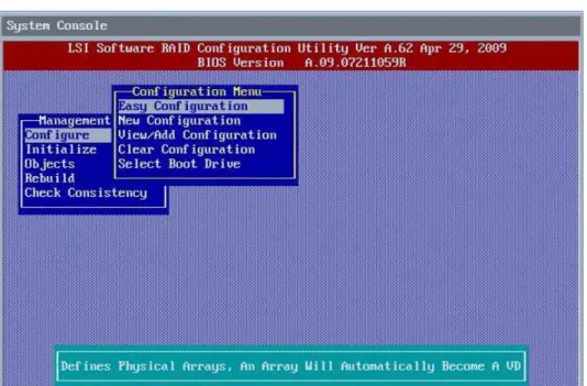
Management Menu
The Management Menu screen appears when you start the LSI Software RAID CU:
Figure 5 LSI Software RAID Configuration Utility Management Menu Screen
LSI Corporation 23 -Embedded MegaRAID Software User Guide
March 2012
Chapter 3: LSI Software RAID Configuration Utility Configuration Menu
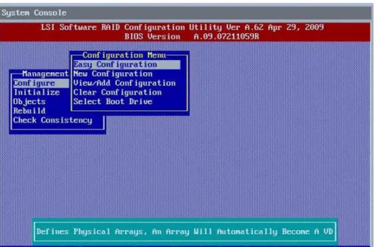
3.3
Configuration Menu
Use the Configuration Menu screen to configure drive groups and virtual drives. This section describes the configuration options.
3.3.1
Configuration Menu Options
The Configuration Menu screen provides four methods to modify and/or create a virtual drive configuration: Easy Configuration, New Configuration, View/Add Configuration, and Clear Configuration, as shown in the following figure:
Figure 6 LSI Software RAID Configuration Menu
Table 1 describes these methods. The Configuration Menu has an Advance submenu that enables you to set specific options. The available options depend upon the configuration method you use.
Table 1 LSI Software RAID Configuration Utility – Configuration Menu
Option Description
Easy Configuration Easy Configuration automatically associates every drive group with one virtual drive. Through the Advance Menu, Easy Configuration allows you to modify the RAID level and stripe size. Section 3.5.2, Using Easy Configuration, on page 26, provides detailed instructions.
New Configuration New Configuration allows you to modify the RAID level, stripe size, virtual drive size, and disk spanning (associating virtual drives with multiple drive groups). If you select New Configuration, the CU deletes the existing configuration information on the selected controller when saving the new configuration. Section 3.5.3, Using New Configuration, on page 30, provides detailed instructions.
View/Add Configuration
View/Add Configuration allows you to control the same virtual drive parameters as New Configuration without disturbing the existing configuration information. The View/Add configuration also allows you to enable the
Configuration on Disk feature. Section 3.5.4, Using View/Add Configuration, on page 34, provides detailed instructions. Clear Configuration Clear Configuration erases the current configuration information. Section 3.6, Clearing a Storage Configuration, on
page37, provides detailed instructions.
Specify Boot Drive Specify Boot Drive enables you to specify a virtual drive as the boot drive on the controller, if you have created virtual drives. Section 3.7, Configuring a Bootable Virtual Drive, on page 38, provides detailed instructions.
3.4
Configuring Drive Groups and Virtual Drives
The following sections provide detailed instructions for configuring drive groups and virtual drives with the LSI Software RAID CU.
The number of physical drives in a specific drive group determines the possible RAID levels that you can implement with the drive group.
RAID 0 requires from one to eight physical drives.
RAID 1 requires two physical drives.
RAID 5 required three to eight physical drives.
RAID 10 requires four, six, or eight physical drives.
3.5
Creating a Storage Configuration
This section explains how to use the LSI Software RAID Configuration Utility to configure RAID drive groups and virtual drives to create storage configurations:
3.5.1
Selecting the Configuration Method
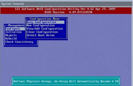
Easy Configuration automatically associates each drive group with one virtual drive. Follow these steps to open the Configuration Menu screen, and select a configuration method:
1. On the Management Menu screen, highlight Configure with your cursor, and press Enter.
The Configuration Menu screen appears, as shown in the following figure.
NOTE Use drives with the same capacity when you create a storage configuration. If you use drives with different capacities in one drive group, the CU limits each drive to the capacity of the smallest drive.
LSI Corporation 25 -Embedded MegaRAID Software User Guide
March 2012
Chapter 3: LSI Software RAID Configuration Utility Creating a Storage Configuration
Figure 7 Configuration Menu Screen
2. Select a configuration option.
— Easy Configuration – Automatically associates every drive group with one virtual drive.
— New Configuration – Clears the existing configuration and lets you create a new configuration.
— View/Add Configuration – Retains the existing storage configuration and adds new drives to it (this method does not cause any data loss).
— Clear Configuration – Clears the existing configuration.
3. Press Enter.
The configuration screen appear for the configuration option that you selected.
A dialog box warns that you will lose data if you select Clear Configuration or New Configuration. The following sections describe the configuration steps for each configuration method.
CAUTION If you choose to clear the existing configuration or to create a new configuration, the system deletes all of the existing data in the configuration. Make a backup of any data that you want to keep before you choose an option.
3.5.2
Using Easy Configuration
Follow these instructions to create a configuration with Easy Configuration, either with or without redundancy:
1. On the Management Menu screen, highlight Configure with your cursor, and press Enter.
The Configuration Menu screen appears, as shown in the following figure.
LSI Corporation 27 -Embedded MegaRAID Software User Guide
March 2012
Chapter 3: LSI Software RAID Configuration Utility Creating a Storage Configuration
2. Use your cursor to highlight Easy Configuration and press Enter.
The following screen appears.
Figure 9 Easy Configuration – Array Selection Menu
3. Press the space bar to select a drive and add it to the drive group. 4. Repeat step 3 to add additional drives to the drive group.
5. Press F10 to continue configuration.
The Select Configurable Array(s) dialog box appears, as shown in the following figure.
6. Press the space bar to select the drive group.
7. Press F10 to continue configuration.
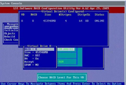
The Virtual Drive(s) Configured dialog box appears, as shown in the following screen. This screen shows the virtual drive number, RAID level, drive group size, number of stripes, stripe size and drive status.
Figure 11 Virtual Drive Parameters Dialog Box
8. Change the virtual drive options from the defaults listed on the screen as needed. Use the cursor keys to navigate
between the virtual drive parameters and press Enter to select an option. Here are brief explanations of the virtual drive options:
— RAID Level – The drop-down menu lists the possible RAID levels for the virtual drive. In some cases, only one RAID level is available, depending on the number of drives in the drive group.
— Size – This setting specifies the capacity of the virtual drive.
— Disk Write Cache Policy – When the disk Write Cache is On, a write transaction is considered to be complete when all the data has been written to the disk cache. When disk Write Cache is Off, the write transaction is complete only when the data has been written to the disk.
— Read Ahead Policy – When disk Read Ahead is On, extra data is read sequentially ahead of the data that is actually requested, and this extra data is stored in cache memory. If the additional read-ahead data is then requested, it can be read faster from the cache than from the disk directly. This setting speeds up reads for sequential data, but there is little improvement when accessing random data.
— Accept – Select this option to accept the virtual drive parameters.
LSI Corporation 29 -Embedded MegaRAID Software User Guide
March 2012
Chapter 3: LSI Software RAID Configuration Utility Creating a Storage Configuration
9. Highlight Accept and press Enter after you select your virtual drive parameters. The virtual drive configuration appears, as shown in the following screen.
Figure 12 Virtual Drive Configuration Parameters
10. Press any key to continue.
11. Click Yes at the prompt to save the configuration.
The LSI Software RAID Configuration Utility begins a background initialization of the virtual drives.
New RAID 5 virtual drives require a minimum number of drives for a background initialization to start. If there are fewer drives than the minimum, the background initialization will not start.
3.5.3
Using New Configuration
If you select New Configuration, the CU deletes the existing configuration information on the selected controller when it saves the new configuration.
Follow these instructions to create a configuration with Easy Configuration, either with or without redundancy:
1. On the Management Menu screen, highlight Configure with your cursor, and press Enter.
The Configuration Menu screen appears, as shown in the following figure.
LSI Corporation 31 -Embedded MegaRAID Software User Guide
March 2012
Chapter 3: LSI Software RAID Configuration Utility Creating a Storage Configuration
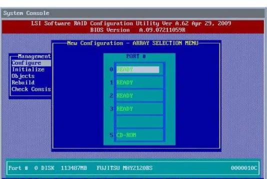
2. Highlight New Configuration with your cursor, and press Enter.
The following screen appears. This screen displays the drives.
Figure 14 New Configuration – Array Selection Menu
3. Press the space bar to select a drive and add it to the drive group. 4. Repeat step 3 to add additional drives to the drive group.
5. Press F10 to continue the configuration.
The Select Configurable Array(s) dialog box appears, as shown in the following figure.
6. Press the space bar to select the drive group.
7. Press F10 to continue the configuration.
The Virtual Drive(s) Configured dialog box appears, as shown in the following screen. This screen shows the virtual drive number, RAID level, drive group size, number of stripes, stripe size and drive status.
Figure 16 Virtual Drive Parameters Dialog Box
8. Change the virtual drive options from the defaults listed on the screen as needed. Use the cursor keys to navigate
between the virtual drive parameters and press Enter to select an option. Here are brief explanations of the virtual drive options:
— RAID Level – The drop-down menu lists the possible RAID levels for the virtual drive. In some cases, only one RAID level is available, depending on the number of drives in the drive group.
— Size – This setting specifies the capacity of the virtual drive.
— Disk Write Cache Policy – You can disable the write cache option when you create a virtual drive, but you can enable this option later using the configuration utilities. When the disk Write Cache is On, a write transaction is considered to be complete when all the data has been written to the disk cache. When disk Write Cache is Off, the write transaction is complete only when the data has been written to the disk.
— Read Ahead Policy – When disk Read Ahead is On, extra data is read sequentially ahead of the data that is actually requested, and this extra data is stored in cache memory. If the additional read-ahead data is then requested, it can be read faster from the cache than from the disk directly. This setting speeds up reads for sequential data, but there is little improvement when accessing random data.
— Accept – Select this option to accept the virtual drive parameters.
LSI Corporation 33 -Embedded MegaRAID Software User Guide
March 2012
Chapter 3: LSI Software RAID Configuration Utility Creating a Storage Configuration
9. Highlight Accept with your cursor, and press Enter after you select your virtual drive parameters. The virtual drive configuration displays, as shown in the following screen.
Figure 17 Virtual Drive Configuration Parameters
10. Press any key to continue.
11. Click Yes at the prompt to save the configuration.
The LSI Software RAID Configuration Utility begins a background initialization of the virtual drives.
New RAID 5 virtual drives require a minimum number of drives for a background initialization to start. If there are fewer drives than the minimum, the background initialization will not start.
3.5.4
Using View/Add Configuration
View/Add Configuration allows you to control the same virtual drive parameters as New Configuration without disturbing the existing configuration information.
Follow these instructions to create a configuration with Easy Configuration, either with or without redundancy:
1. On the Management Menu screen, highlight Configure with your cursor, and press Enter.
The Configuration Menu screen appears, as shown in the following figure.
LSI Corporation 35 -Embedded MegaRAID Software User Guide
March 2012
Chapter 3: LSI Software RAID Configuration Utility Creating a Storage Configuration
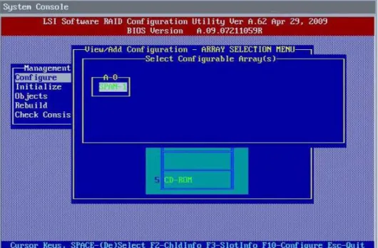
2. Highlight View/Add Configuration with your cursor, and press Enter.
The following screen appears.
Figure 19 View/Add Configuration – Array Selection Menu
3. Press the space bar to select a drive and add it to the drive group. 4. Repeat step 3 to add additional drives to the drive group.
5. Press F10 to continue the configuration.
The Select Configurable Array(s) dialog box appears, as shown in the following figure.
6. Press the space bar to select the drive group.
7. Press F10 to continue the configuration.
The Virtual Drive(s) Configured dialog box appears, as shown in the following screen. This screen shows the virtual drive number, RAID level, drive group size, number of stripes, stripe size and drive status.
Figure 21 Virtual Drive Parameters Dialog Box
8. Change the virtual drive options from the defaults listed on the screen as needed. Use the cursor keys to navigate
between the virtual drive parameters and press Enter to select an option. Here are brief explanations of the virtual drive options:
— RAID Level – The drop-down menu lists the possible RAID levels for the virtual drive. In some cases, only one RAID level is available, depending on the number of drives in the drive group.
— Size – This setting specifies the capacity of the virtual drive.
— Disk Write Cache Policy – You can disable the write cache option when you create a virtual drive, but you can enable this option later using the configuration utilities. When the disk Write Cache is On, a write transaction is considered to be complete when all the data has been written to the disk cache. When disk Write Cache is Off, the write transaction is complete only when the data has been written to the disk.
— Read Ahead Policy – When disk Read Ahead is On, extra data is read sequentially ahead of the data that is actually requested, and this extra data is stored in cache memory. If the additional read-ahead data is then requested, it can be read faster from the cache than from the disk directly. This setting speeds up reads for sequential data, but there is little improvement when accessing random data.
— Accept – Select this option to accept the virtual drive parameters.
— SPAN – Choose whether to span drive groups. This setting is available only for RAID 10 drive groups.
9. Highlight Accept with your cursor, and press Enter. The virtual drive configuration displays.
10. Press any key to continue.
11. Click Yes at the prompt to save the configuration.
The LSI Software RAID Configuration Utility begins a background initialization of the virtual drives.
New RAID 5 virtual drives require a minimum number of drives for a background initialization to start. If there are fewer drives than the minimum, the background initialization will not start.
LSI Corporation 37 -Embedded MegaRAID Software User Guide
March 2012
Chapter 3: LSI Software RAID Configuration Utility Clearing a Storage Configuration
3.6
Clearing a Storage Configuration
To clear a storage configuration, follow these steps:
1. On the Management Menu screen, select Configure > Clear Configuration.
The following screen appears.
Figure 22 Clear Configuration Option
2. At the prompt, select Yes to confirm and press Enter. The virtual drive is deleted from the configuration.
3.7
Configuring a Bootable Virtual Drive
The default boot virtual drive is LD 0. If you change the boot drive to another virtual drive, the BIOS and the CU preserve this change. However, if you delete the new boot virtual drive, you must be sure to configure another virtual drive for booting. The CU does not automatically select a different boot virtual drive.
Follow these steps to configure a bootable virtual drive:
1. On the Management Menu screen, select Configure > Select Boot Drive.
The following screen appears.
Figure 23 Select Boot Drive Option
2. Select a virtual drive from the list to be the designated boot drive. The virtual drive is configured to be the boot drive.
3.8
Initializing Virtual Drives
This section explains the two methods used to initialize a virtual drive with the LSI Software RAID Configuration Utility. If the Fast Init property is enabled, fast initialization is used. In fast initialization, the LSI Software RAID CU quickly writes zeroes to the first and last 8-MB regions of the new virtual drive.
If the Fast Init property is not enabled, the utility performs a complete initialization on the virtual drive. This process can take a long time if the physical disk drives are large.
LSI Corporation 39 -Embedded MegaRAID Software User Guide
March 2012
Chapter 3: LSI Software RAID Configuration Utility Initializing Virtual Drives
3.8.1
First Initialization Method
Follow these steps to initialize a virtual drive using the Initialize menu.
1. On the Management Menu screen, highlight Initialize with your cursor, and press Enter.
The list of virtual drives appears.
2. Use the cursor to highlight the virtual drive you want to initialize (if there is more than one virtual drive). 3. Press Enter.
The following screen appears.
Figure 24 Initializing a Virtual Drive – First Method
4. Press F10.
5. Select Yes at the prompt and press Enter to begin the initialization. A graph shows the progress of the initialization until it is complete. 6. After the initialization is complete, press Esc to return to previous menus.
If you press Esc while initialization is in progress, the following options appear:
— Stop – (Available only if Auto Resume is enabled on the controller: Management Menu > Objects >
Adapter > AutoResume.) The initialization is stopped, and the CU stores the percentage of the initialization already completed. If Auto Resume is enabled, and if Fast Init is not enabled, the initialization resumes where it left off when you restart it, instead of starting over from 0 percent.
— Continue – The initialization continues normally.
3.8.2
Second Initialization Method
Follow these steps to initialize a virtual drive using the Objects menu.
1. On the Management Menu screen, select Objects > Virtual Drive.
A list of configured virtual drives appears.
2. Use the cursor to highlight the virtual drive you want to initialize (if there is more than one virtual drive), and pressEnter.
The following screen appears.
Figure 25 Initializing a Virtual Drive – Second Method
3. Highlight Initialize with your cursor on the virtual drive submenu, and press Enter. 4. Select Yes at the prompt, and press Enter.
The utility displays a bar graph showing the initialization progress.
5. When initialization completes, press Esc to return to the previous menu.
If you press Esc while initialization is in progress, the Stop, Continue, and Abort options are available, as explained in Section 3.8.1, First Initialization Method, on page 39.
LSI Corporation 41 -Embedded MegaRAID Software User Guide
March 2012
Chapter 3: LSI Software RAID Configuration Utility Rebuilding a Drive
3.9
Rebuilding a Drive
The LSI Software RAID Configuration Utility enables you to rebuild a drive of a redundant drive group if the drive group has a failed drive. If the failed drive is still good (that is, if the drive is physically present and its capacity is greater than or equal to the defined capacity of the drive group), it will be rebuilt. If the drive is too small, an error message appears and the CU does not allow the drive to be rebuilt.
Follow these steps to rebuild a drive:
1. On the Management Menu screen, highlight Rebuild and press Enter.
2. When the list of drives appears, highlight the failed (FAIL) drive that you want to rebuild and press the spacebar to select it.
3. After you select the drive, press F10 to start the rebuild, and then select Yes at the confirmation prompt. The rebuild process begins, and a graph shows the progress of the rebuild until it is complete. Although the CU changes the disk drive state to Rebuild at this point, the change does not appear on the screen while the rebuild is in progress.
If the CU detects a media error on the source drive during rebuild, it initiates a sector read for that block. If the sector read fails, the CU adds entries to the Soft Bad Block Management (SBBM) table, writes this table to the target drive, and displays an error message.
Additional error messages appear if the SBBM table is 80 percent full or 100 percent full. If the SBBM table is completely full, the rebuild operation is aborted, and the drive is marked as FAIL.
4. When the rebuild is complete, the CU displays the message that the rebuild is successful.
5. Press Esc to display the Management Menu screen.
The state of the rebuilt disk drive changes from FAIL to ONLIN.
If you press Esc while the rebuild is running, the following options display:
— Stop – (Available only if AutoResume is enabled on the adapter: Management Menu > Objects > Adapter >
AutoResume.)
The rebuild is stopped, and the CU stores the percentage of the rebuild already completed. If AutoResume is enabled, the rebuild resumes where it left off when you restart it, instead of starting over from 0 percent.
— Continue – The rebuild continues normally.
— Abort – The rebuild is completely aborted and the disk drive remains in the FAIL state. If you restart the rebuild, it begins at 0 percent.
3.10
Creating a Global Hotspare Drive
The LSI Software RAID Configuration Utility enables you to create global hot spare drives to protect against data loss. A hot spare is an unused drive that you can use to rebuild the data from a failed drive and re-establish redundancy, in case of a disk failure in a redundant RAID drive group (RAID 1, RAID 5, or RAID 10).
NOTE You cannot rebuild a failed drive if the drives capacity is even 1 byte smaller than the defined capacity of the drive group.
NOTE Dedicated hot spare drives are not supported by the LSI Software RAID Configuration Utility.
NOTE When you select a drive to change into a global hot spare, be sure it is the same type of drive as the drives in the drive group that it will protect.
You can create a hotspare when you are configuring a new storage configuration, as described in the previous sections. To add a hotspare drive to an existing redundant storage configuration, follow these steps:
1. On the Management menu, select Configure > View/Add Configuration.
2. Select Physical Drive.
A list of physical drives appears.
3. Highlight an unconfigured drive or a Ready drive with your cursor, and press Enter. The following screen appears.
4. In the HotSpare dialog box, select Yes and press Enter.
5. Select Yes from the pop-up menu to create the hot spare drive.
LSI Corporation 43 -Embedded MegaRAID Software User Guide
March 2012
Chapter 3: LSI Software RAID Configuration Utility Checking Data Consistency
3.11
Checking Data Consistency
The Check Consistency feature verifies the consistency of the data on the physical drives that are part of RAID 1, 5, or 10 virtual drives. The LSI Software RAID Configuration Utility automatically corrects any differences found in the data when a consistency check is run.
Follow these steps to check consistency:
1. On the Management Menu screen, highligh