ATM
Agilent Technologies Broadband Series Test System
Application Note
LAN users are used to the speed and reliability of their local networks, and as business needs force LANs to expand beyond their original limited boundaries, services such as leased lines, ISDN, X.25, SMDS and frame relay have been used to interconnect LANs. But users expect the same speed and reliability for traffic routed over intermediate metropolitan and wide area links. This demand places substantial commercial pressure on service providers and equipment
manufacturers to create devices that can link different communications technologies into a seamless network.
This need for faster computer
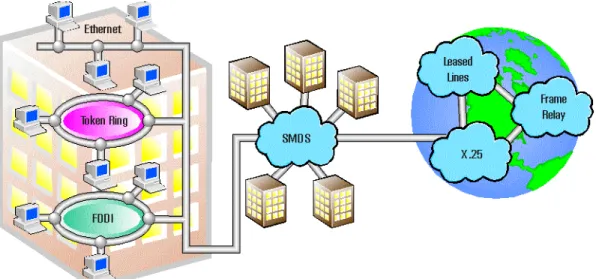
networking and higher speed wide area network services is the key driver of early ATM applications. ATM has been identified as an all in-one technology - incorporating backbone, LAN and WAN into one network architecture. But the current industry viewpoint is that the implementation of ATM will only be successful if introduced in a gradual, incremental approach. The installed base of legacy technologies must be offered an upgrade path to reduce the entry cost of ATM. Interworking between installed services in data communication is therefore key to the success of ATM. A typical data network in place today is shown in Figure 1. In time, ATM can replace each of these network islands. But current ATM products and services need to be refined before they can replace all of the existing equipment and technologies.
Editor’s Note: Reader not familiar with either ATM or Frame Relay may wish to see the background information on page 11.
Interworking Scenarios
Depending on where ATM will be implemented in the WAN, several new interworking interfaces have to be defined. Two major groups ofinterworking scenarios can be identified: network interworking and service interworking.The differences between these scenarios is subtle.
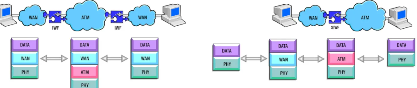
Network interworking over ATM uses the ATM bearer service as the transport bridge, or pipe, between different WAN network islands of the same network technology (i.e. SMDS or frame relay). The interworking function (IWF) is responsible for mapping WAN traffic into the ATM transport service. Two equal IWFs, one on each side of the ATM network, allow WAN users to access the ATM connection service and send their data over the ATM backbone without knowing the mechanics of the ATM network. A closer look at the protocol stack shows the transparency of the IWF to the WAN and higher layer protocols. Unlike network interworking, where encapsulated WAN data is bridged over the ATM network, service interworking involves the translation of protocols and semantics so that an ATM end-node can Figure 1: Typical data network in place today.
communicate with another end-node (e.g. a frame relay interface on a router). When implementing a service
interworking function (SIWF), only the data carried over the WAN is mapped into ATM cells. The protocol
information used by the WAN protocol is translated into the appropriate ATM semantics. No network-specific protocol from one side will be carried over the other network. None of the WAN overhead (headers, management information) is transported over the ATM network. An ATM end-user can
communicate without knowing that the partner station is connected to a different WAN interface; the interconnected network is service transparent. Higher layer applications also interwork from one WAN technology to another. In some cases (e.g. LAN), higher layer traffic encapsulation may not be the same on both networks. Interworking must also translate between different higher layer encapsulation schemes and headers. This adds complexity to the SIWF implementation.
ATM Interworking Functions
Each existing networking technology has its own attributes and protocol functions to provide network services. Examples are switching types, addressing schemes, congestion control mechanisms and others.An interworking device needs to translate service specific parameters and functions to ATM, taking the best possible advantage of available ATM facilities. The IWF that is responsible for the connection of two dissimilar
networks is service-specific (e.g. FR/ATM,SMDS/ATM, FDDI/ATM) as will be actual interworking equipment used for a given technology pair. Figure 2: Network and service interworking.
What is an Interworking
Function?
An ATM IWF is a set of definitions standardizing how a multiport device connecting two networks (FR/ATM, LAN/ATM) performs the translation from one service to another. Translation functions described may cover:
• Address translation
• Congestion indication translation • Connection status management • Protocol encapsulation and
decapsulation • Policing translation
• Connection setup and signalling translation
Not all of these functions must be translated in all cases. Simple network interworking can be performed by only translating the WAN address field into an ATM virtual channel and by
encapsulating the WAN traffic into ATM PDUs and (vice versa).Translation for policing and management information is not needed by a bare-bones minimal IWF.
To make the transmission more efficient, the translation of congestion information from the WAN traffic into ATM cells maybe added to the IWF. When cell discarding is needed in the ATM network, cells containing tagged WAN traffic will be discarded first. In this way overall throughput of low discard priority frames will be increased. Similarly, other features can
progressively be added to make the IWF more intelligent.
Where the IWF is
Implemented
The IWF can be implemented into a stand-alone interworking device or can be incorporated into the software and hardware of switches, multiplexers and interface cards. When interworking with an existing network, the IWF probably will be implemented in the bridging or routing component, in an access multiplexer or switching device. Interworking functions may also be embedded in bridges, routers, DSUs and network servers.
There are scores of different WAN technologies and many of them will eventually interwork with ATM. Depending on the functionality of the interworking device, SIWFs or network IWFs may be implemented. From this point onwards, this solution note focuses on an example of a frame relay to ATM IWF.
Frame Relay Interworking
with ATM
In early applications, devices
interworking frame relay and ATM will use undoubtedly ATM as a transport media to connect frame relay network islands. Connections will be permanent and manually provisioned by the network operator. As defined earlier, this is a case of PVC network interworking. An implementation agreement between the ATM Forum and the Frame Relay Forum defines a network interworking function in “Frame Relay/ATM Network Interworking Implementation
Agreement”, FRF.5. It includes: • How FR frames are transported over
ATM
• How FR channels are mapped into ATM virtual channels
• Different options for the translation of discard priority information • Different options for congestion
information translation
• How the link integrity is guaranteed over the interworking device The following paragraphs highlight major definitions and explain the associated functions.
Traffic Mapping
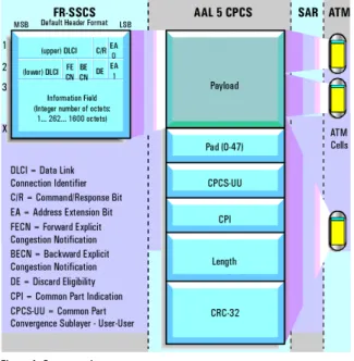
The main task of the IWF is to map frame relay frames to and from the ATM transport service. This mapping is done in a simple manner. Some of the FR frame content, such as the CRC-16, is not needed and simply stripped off (the frame relay CRC is redundant because AAL-5protects its PDU with the AAL-5CRC). The mapping of frame relay to AAL-5 CPCS is performed by a sub-layer known as the frame relay Service Specific Convergence Sublayer (FR-SSCS). The FR-SSCS is mapped into the AAL-5 CPCSSDU and then segmented using the normal AAL-5 procedures.
Connection Multiplexing
The IWF is also responsible for the routing of transmitted frames. On the ATM side, information is equipped with two routing information fields; the DLCI information at the FR-SSCS and the VCI/VPI of each cell after segmentation. This duplicity leads to two possible methods of connection mapping over the IWF: one-to-one multiplexing and many-to-one multiplexing.One-to-one multiplexing map search FR logical connection(DLCI) into a different ATM VC. Multiplexing is performed at the ATM layer using VCI/VPIs. The DLCI value in the FR-SSCSPDU is ignored by the destination equipment because each logical link is uniquely identified by the VP/VC in the ATM cell header. If no value for the FR-SSCSDLCI was agreed on,1022 is used as a default.
Many-to-one multiplexing makes use of the DLCI in the FR-SSCS to multiplex the different FR logical connections. The multiple DLCI streams are mapped into one single ATM VC. This piping allows the interconnection of different DLCIs between two end-users over one virtual ATM connection. This is only possible if all the DLCI channels terminate at the same place and the ATM VC functions as a simple point-to-point link. This multiplexing scheme is important, as some carriers will have a surcharge for each VC set-up, so minimizing the number of VCs used has a cost advantage. In this case the destination needs to examine the DLCI in the AAL-5payload as well as the VP/VC to fully demultiplex the traffic.
Discard Eligibility and Cell
Loss Priority Mapping
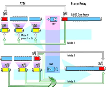
Frame relay and ATM both have traffic policing mechanisms to handle traffic that doesn’t meet the committed traffic transfer rate contract. ATM’s separation of non-conforming cells is called the Generic Cell Rate Algorithm (GCRA). ATM tags cells that exceed the allowed traffic limit by setting the CLP. Frame relay has a similar mechanism based on the Committed Information Rate algorithm (CIR) which results in setting the DE bit in the frame header. Marked cells or frames may still traverse the network, but when congestion is experienced, this is the first traffic to be discarded.Interworking units must both preserve the discard priority information and maintain the efficiency of the destination network by accurately simulating its behavior. Simply retaining the discard priority information can be
accomplished by copying the frame relay DE bit to, or from, the FR-SSCS frame. This is labelled as Mode 2 in Figure 5. In addition, by mapping frame relay DE bits into the cell loss priority (CLP), cells containing tagged FR frames will be discarded first if congestion occurs. The overall throughput of high priority frames will increase. This is labelled as Mode 1 in Figure 5.
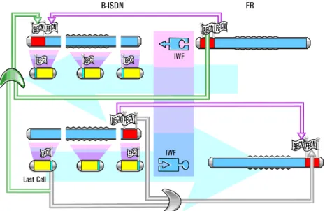
Congestion Indication
Both frame relay and ATM support a mechanism to indicate congestion to network devices. While FR supports congestion indication in both forward and backward directions (FECN and BECN bits), ATM only supports forward congestion (EFCI field). Figure 6 illustrates the mapping of FECN/BECN and EFCI information.One special case is when the last ATM cell of a received frame has the EFCI set. Because frame relay supports backward congestion, this activates the BECN of the next FR-SSCS to be set.
Link Integrity Management
Frame relay network management relies upon the exchange of status management messages to verify connectivity (as defined by ITU Q.933 Annex A and ANSI T1.617 Annex D). Heartbeat polling is used to verify the operation of a PVC link. If the heartbeat poll fails, the link is declared inoperable and the management system is informed. The network management system usually maintains a table of link status indicators, and issues alarms based on the data in this table. ATM uses a procedure similar to heartbeat polling; special OAM-F5 cells verify link integrity as defined by I.610 OAM.When interworking, the FR network management system is still used; but, instead of heartbeat polling, ATM virtual channel status information is directly mapped into the network management system’s link status table. In this way the heartbeat polling functions are “fudged” by the IWF.
The first service interworking definition by the Frame Relay Forum will not support frame relay interworking with VC-based multiplexing. In LLC encapsulation more than one routed and bridged LAN protocol will be carried over a single VC.
The receiving system must distinguish between different protocols on a single VC. LLC protocol encapsulation adds additional information to each bridged or routed packet as a Logical Link Control (LLC) and a Sub-Network Attachment Point (SNAP) header containing an identification of the protocol (e.g. FDDI, TCP/IP).
A different approach is taken when encapsulating bridged or routed LAN traffic into frame relay frames. A Network Level Protocol Identification (NLPID) header is attached to each LAN packet to identify the carried protocol type (e.g. bridged Ethertype, routed IP). This NLPID header does the same job as the ATM LLC header.
The maximum frame relay frame might be smaller than the LAN packet to be transported, so RFC 1490 defines how a LAN packet can be segmented to fit into FR frames.
An interworking device must not only handle header protocol translation, but also payload conversion by translating RFC 1490 encapsulated LAN traffic to RFC 1483 encapsulated AAL-5 frames and vice versa.
Service Interworking
There are two major limitations experienced when networkinterworking. The transport of frame relay headers over the ATM network limits transmission efficiency, but more importantly, both stations must have frame relay implemented (either by being connected to a frame relay network, or by emulating frame relay at their transmission port).
Service interworking addresses these limitations. Only the payload is moved between frame relay and ATM. The header content of one protocol is translated into the other protocol. A service interworking connection is transparent; users do not need to know if the other party that they are
communicating with uses the same network technology. An ATM
end-station can communicate with frame relay end-stations without performing any FR-specific functions.
Depending on the service being
interworked, a higher level payload data translation may be necessary. One such example is when LAN traffic is moved between frame relay and ATM. The Internet Engineering Task Force’s (IETF) RFCs define how protocols are transported over different network technologies. These RFCs are used by equipment manufacturers when implementing LAN encapsulation over wide area networks. Two encapsulation schemes are of interest for frame relay and ATM interworking:
• RFC 1483, “Multiprotocol Encapsulation over ATM” • RFC 1490, “Multiprotocol
Encapsulation over Frame Relay” RFC 1483 defines two methods to transport commonly-used bridged or routed LAN protocols over ATM AAL-5; LLC encapsulation and VC-based multiplexing.
SVC Network Interworking
Switched virtual circuit signalling will permit dynamic channel allocation using signalling protocols. To do this, an interworking unit must handle call-related messages based on Frame Relay Q.933 and ATM Q.2931. Link parameter translation from CIR, Be, Bc on the frame relay side to CDV, SCR, PCR on the ATM side is just one example of this kind of translation. Morestandardization is still needed in this area.
Internetworking Test
Requirements
A new interworking function will face many different types of tests as it moves from R&D engineering into a product. R&D engineering teams usually simulate interworking functions and observe the resulting behavior. Stressing a specific function not only tests its operation, but can help optimize underlying algorithms. After development has been completed, interworking functions are usually integrated into routers, switches and other products by a systems integration team. This group must verify that existing product functionality is not affected by new features.
This lengthy process is called regression testing, and is time-consuming since all previous features must be carefully tested.
Regression testing is repeated each time that a new version of a product is released, so a programmable test environment is therefore highly desirable.
Quality assurance teams must not only verify correct operation, but quantify the reliability and performance of new products. Reliability is usually established by extensive testing of the DUT’s ability to handle faulty traffic. The test equipment must be able to generate both normal and abnormal
Performance testing verifies the limits of the device under test when operating under extreme conditions. To prove the DUT’s integrity, the test equipment must generate realistic traffic. Real-world traffic is captured and played back, on a statistical representation of real world traffic, is used for this purpose. Service providers often perform acceptance testing to verify the operation of new equipment considered for purchase. Such testing usually measures conformance and interoperability with other vendors’ equipment.
Service providers must deliver the quality of service (QoS) specified in their customer contracts. QoS is defined by quantifiable service parameters and must be measured not just for individual pieces of equipment, but across entire networks. Being able to objectively measure network performance is a key consideration in customer satisfaction for service providers.
While it is not possible to cover all the issues related to testing the
implementation of internetworking functions in this paper, the following examples test some of the above areas. All tests assume that the device under test is an FR/ATM interworking unit (IWU).
Connectivity Testing
Connectivity testing verifies that the data link is working correctly. Typical tests are:
• Address translation and mapping table functionality
• Protocol translation verification • Protocol encapsulation and
decapsulation
• Discard priority information • Congestion indication translation • Connection status management
Testing the Discard Priority
Mapping
The basis of all ATM traffic management is the tagging of non-conforming cells. As earlier described, two modes can be implemented to translate tagging between the ATM CLP bit and the frame relay DE bit.
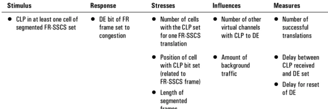
Factors listed in Figure 7 can help define a test setup to verify the mapping function from ATM to frame relay when Mode 1 of the Discard Priority Mapping is used.
Generally, test results are more
meaningful when the system under test is moderately busy. This is done by loading the system with background traffic as well as the test traffic which is used to carry out measurements. However, the test setup does not intend to test the functionality of the policing mechanisms, so background traffic should always be within allowed limits. Different stimulus events can be placed in a sequence. The more the system is stressed, the longer the delay before the cell appears with the CPL bit set or the shorter the frame relay SSCS frame. CLP to DE translation performance can be tested by setting up a few extreme cases. Receiver pattern matchers can count events on both sides of the IWU. The counters will match if all the requested DE changes actually occurred. Varying the background traffic load or the distribution pattern of the foreground channel can stress the discard priority mapping function until the counters do not match. Captured traffic can then be examined to determine why the error occurred. Was the CLP mapped into the immediately following frame, or was there a delay? Delays can be determined by examining the timestamps.
Handling Faulty Traffic
How reliable is the system under test? One very important test is the system’s ability to handle faulty traffic. Graceful recovery from a loss of signal, loss of synchronization, or discarded traffic are key to reliability.Some frame relay faults to test for are aborted frames, short frames, non-octet aligned frames, incorrect address lengths, and errored frames. Typical ATM faults include AAL-5 errors, cell mis-sequences, cell loss, and AAL-5 CPCS or CRC32 errors. All of the above frames should be discarded by the system, and the next correct frame should be routed through.
Performance Issues
Performance is an important testing issue since it quantifies how well data is handled.
Throughput, defined as the number of FR PDUs successfully transferred per unit time, is one important value describing frame handling capability. Latency, or the transfer delay of frames, is another performance parameter.
The frame relay portion may be implemented in an interface card. The same applies for ATM, with the connection done over a backplane bus. Unlike a single technology switch, this architecture is highly unsymmetrical and throughput may differ significantly depending on the direction that traffic goes through the IWU (ATM to frame relay or vice versa). Loopback tests cannot identify the cause of problems since they always result in both an ATM-to-frame relay translation and a frame relay-to-ATM translation.
Stimulus Response Stresses Influences Measures
• CLP in at least one cell of segmented FR-SSCS set
• DE bit of FR frame set to congestion
• Number of cells with the CLP set for one FR-SSCS translation • Number of other virtual channels with CLP to DE • Number of successful translations • Position of cell with CLP bit set (related to FR-SSCS frame) • Length of segmented frames • Amount of background traffic • Delay between CLP received and DE set • Delay for reset
of DE
An internetworking test equipment setup should be capable of generating traffic on the ATM side of the SUT and analyzing the frame relay side (and vice versa). The traffic generator and analyzer need to be correlated, and offer fully decoded and easy-to-compare displays of both received and transmitted traffic.
Synchronization is extremely important, especially when analyzing transit delay. What limits the performance of an interworking device? Typically, the frame-handling capacity, buffer capacity, receiver synchronization and backplane performance are the constraining factors.
Testing Framing Capacity
The task of using a look-up table to map each received frame into a FR-SSCS is done by processors. Of course, those processors can only perform a finite number of look-ups per time interval. Performance testing should determine the frame handling performance limit. Two parameters drive the rate at which look-ups can be mapped; frame length and the amount of traffic (percentage of total bandwidth).To test an IWU’s frame-handling capacity, send short frames on top of constant background traffic into it and count the outgoing frames. Also count the frames at the receiver side. The limits of the unit’s frame-handling capacity can be found by varying the background load and the burst length until there is a mismatch between the two counters.
Testing Buffers
Buffers are built into the SUT to store incoming frames. They have to be able to capture the longest frame allowed. Sending a burst of long frames interleaved with short ones tests the buffer allocation algorithm. Many short frames tests the speed and reliability of buffer allocation, while long frames test the ability of the buffer allocation algorithm to wrap around its physical memory limitation.
Testing Receiver
Synchronization
Frame relay byte synchronization is performed by flags between frames. Sending frames with the minimal time between them, one flag, stresses the synchronization mechanism. ATM synchronizes on the HEC calculation. Inserting HEC errors and varying their quantity stresses the cell synchronization.
Testing Backplane
Performance
ATM and frame relay interface cards sometimes are connected in one device over a backplane bus. All traffic interworking from one network to the other travels over this backplane bus. The IWU’s performance is therefore dependent on the cross traffic traversing the backplane bus. The bus has to be loaded with cross traffic while measuring throughput and latency to determine the behavior of the device under test. To realistically emulate a network environment and load the backplane, all physical ports should be loaded with independent, uncorrelated traffic sources loading different virtual channels with different distribution characteristics. One way to reduce the number of physical generators is to loop back some traffic. But looped back traffic is no longer uncorrelated.
To perform a more representative network emulation, more than one test port should be loaded on both sides and the configuration should be set-up to diversify the channels of different virtual connections.
Traffic Profiles
An IWU’s performance is dependent on several variables:
• Traffic burstiness • Average frame length • Percent total input bandwidth • Number of active virtual channels • Percent load of backbone
To test the real-world behavior of an interworking unit, a traffic generator should be able to generate very realistic traffic. A traffic generator should therefore permit the control of traffic profiles. The exact parameters defining the test profiles are dependent on the equipment under test and the services that are expected to be implemented over the device. For example, an IWU connected between a public frame relay network and a public ATM network will translate more DLCI channels than an access device connecting a few frame relay links to an ATM network.
Service Testing in a Network
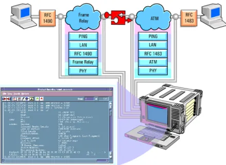
Test equipment is essential to help debug and verify new links involving an interworking function.One common way to identify an end-to-end connection is to send a “ping” message from a workstation (or tester) at one end of the link to another
workstation (or tester) at the other end. A ping message, defined in Internet Control Message Protocol (ICMP), is sent by one TCP/IP user to a destination defined by the IP address. If the destination station receives this echo request message, it formulates an echo reply and sends it back to the origin. If no ping response is received, the ping request message needs to be tracked to see were it was mis-routed.
But not only debugging can be performed this way. Service performance measurements such as transfer delays for a TCP application can be measured in each segment of a running network.
The test system checking the ping message must be capable of decoding the ICMP message on every protocol stack involved. When network interworking, this implies that the tester needs to be able to make time-correlations for different access points and over every implemented protocol stack.
Summary
ATM technology is well-proven, and many service providers are looking at implementing ATM in WAN
environments. The ability of ATM to interwork with existing networks will be critical to its success.
From a service perspective, supporting many interworking interfaces will be important because one limit to the success of a new technology is the installed base. One of the first
standardized interworking scenarios is that between frame relay and ATM. This paper covered some of the tasks a FR/ATM IWU must perform, and pointed out important test issues. We expect that future IWUs will support not just network interworking, but also service interworking. To guarantee the correct function of service interworking, a test system needs to be able to verify
the translation of RFC 1483 to and from RFC 1490.
As virtual channel services become available, support for signalling translation through the interworking device will be required and this is not an easy task. Only powerful test equipment supporting multiport, multiprotocol time-correlated emulation will be able to help develop and verify the correct functionality of such complex translation schemes.
A Note to Readers Familiar
with ATM But Not Frame
Relay
Frame relay (FR) is a fast
packet-switching service that uses variable length packets to transport data over a wide area. It is an evolution of X.25 that takes advantage of the superior transmission quality of today’s data lines to achieve faster transmission by reducing error checking overhead. Frame relay supports data transmission rates up to 2 Mb/s, and the Frame Relay Forum is currently working on a high capacity 45 Mb/s network-network interface
Each FR frame has a multifield header. The address field is called Data Link Connection Identifier (DLCI) and is only of local significance just like VCI/VPI indicators in ATM. Because the DLCI is a virtual channel identifier, different logical frame relay links can share the same physical link. Depending on the number and length of frames sent, each connection can access various amounts of available bandwidth.
The frame header includes fields for: • Forward explicit congestion
notification (FECN)
• Backward explicit congestion notification (BECN)
• Discard eligibility (DE bit) indicating the discard priority of a frame
The FECN bit is similar to the ATM EFCI congestion indication in the PTI field of an ATM cell. The DE bit has an ATM counterpart in the CLP bit of an ATM cell.
Frame relay has permanent and switched virtual connection (PVC and SVC) services. Most of today’s FR implementations are a low-cost PVC alternative to leased line connections and other data networks.
Frame Relay WAN applications are booming world-wide.
Frame Relay/ATM interworking standardization is very advanced for two reasons:
i) the deployment of both technologies is preceding at a rapid pace, forcing interworking
ii) the Frame Relay Forum and the ATM Forum have cooperated to produce a common interworking agreement This interworking agreement is available to guide the creation of interoperable FR/ATM interworking units. The Interworking Function (IWF) which translates FR to ATM and vice versa is defined in ITU-T I.555 and the Frame Relay Forum implementation
agreement, “Frame Relay/ATM Network Interworking Implementation
A Note for Readers Familiar
with Frame Relay But Not
ATM
ATM is a cell-switching service using fixed-length 53 byte packets called cells. A five-byte address header indicates the destination of the specific cell. The address field is split into two sub-fields called the virtual channel identifier (VCI) and virtual path identifier (VPI). Just like the DLCI, the VCI/VPI address is a virtual connection and is only of local importance.
Other important header fields are the cell loss priority (CLP) which indicates the priority of a cell in the event that traffic must be discarded. The Payload Type Indicator (PTI) contains the Explicit Forward Congestion Indication (EFCI), comparable to the FECN field in frame relay. ATM does not have any backward congestion capability, but the Operations Administration and Management (OAM) procedures in ITU I.610 define special cell types that can be used to convey similar information.
This protocol structure allows ATM to support the shared access and
bandwidth-on- demand features of FR’s frame switching.
SVC) services. The first ATM
implementations have all been PVC, but an SVC signalling system has been standardized and initial implementations are becoming available.
Traffic transported over ATM has to be divided into small cell payloads of 48 bytes. This process is called
segmentation. Different segmentation and reassembly schemes (ATM adaptation layers or AALs) handle different transmission needs for voice, data or video.
Due to the high speed of ATM, cells are switched in hardware over high bandwidth interfaces. Cells can be transmitted at any speed, with 45 Mb/s, 155 Mb/s, 622 Mb/s and 2.4 Gb/s being standard speeds. The upper limit of ATM transmission speed has yet to be reached; switching fabrics can currently switch cells at rates of gigabits per second, and new technologies capable of switching terabits per second are on the drawing board.
Transmission of constant-length short cells instead of
variable length frames permits the
interleaving of time-sensitive traffic (e.g. digitized telephone traffic) and long transmission frames
(e.g. Internet Protocol traffic) with greater control of transmission delay. This also results in much lower delay variation (jitter).
Much higher bandwidth requirements can also be satisfied with ATM cell switching. All this combines to make ATM a key technology for broadband transmission requirements.
But frame relay is a less drastic change from exiting data networking equipment and will have an important role in the transition to broadband networks.
Acronyms
AAL ATM Adaptation Layer ATM Asynchronous Transfer Mode Bc Burst committed
Be Burst excess
BECN Backward Explicit Congestion Notification
C/R Command/Response bit CDV Cell Delay Variation CIR Committed Information Rate CLP Cell Loss Priority
CPCS Common Part Convergence Sublayer
CRC Cyclic Redundancy Check DE Discard Eligibility
DLCI Data Link Connection Identifier DSU Data Service Unit
EA Address Extension
EFCI Explicit Forward Congestion Indication
FDDI Fibre Distributed Data Interface FECN Forward Explicit Congestion
Notification FR Frame Relay FRF Frame Relay Forum GCRA Generic Cell Ratio Algorithm GFC Generic Flow Control HEC Header Error Control
ICMP Internet Control Message Protocol IEEE Institute of Electrical and Electronic
Engineers IP Internet Protocol
ISDN Integrated Service Digital Network ITU-T International Telecommunication
Union
IWF Interworking Function
LLC Logical Link Control MAN Metropolitan Area Network OAM Operation And Maintenance PCR Peak Cell Rate
PDU Protocol Data Unit PT Payload Type
PVC Permanent Virtual Connection RFC Request For Comment RX Receive
SAR Segmentation And Reassembly SCR Sustainable Cell Rate SDU Service Data Unit
SIWF Service Interworking Function SMDS Switched Multimegabit Data
Service
SNAP Sub-Network Attachment Point SSCS Service Specific Convergence
Sublayer
SUT System Under Test
TCP Transmission Control Protocol TX Transmit
VC Virtual Connection
VCI Virtual Connection Indentifier VPI Virtual Path Identifier WAN Wide Area Network
UNIX is a registered trademark in the United States and other countries, licensed exclusively through X/Open Company Limited.
Copyright © 2000 Agilent Technologies United States:
Agilent Technologies
Test and Measurement Call Center P.O. Box 4026
Englewood, CO 80155-4026 1-800-452-4844
Canada:
Agilent Technologies Canada Inc. 5150 Spectrum Way Mississauga, Ontario L4W 5G1 1-877-894-4414 Europe: Agilent Technologies
European Marketing Organisation P.O. Box 999
1180 AZ Amstelveen The Netherlands (31 20) 547-9999
Japan:
Agilent Technologies Japan Ltd. Measurement Assistance Center 9-1, Takakura-Cho, Hachioji-Shi, Tokyo 192-8510, Japan Tel: (81) 426-56-7832 Fax: (81) 426-56-7840 Latin America: Agilent Technologies
Latin American Region Headquarters 5200 Blue Lagoon Drive, Suite #950 Miami, Florida 33126 U.S.A. Tel: (305) 267-4245 Fax: (305) 267-4286 Asia Pacific: Agilent Technologies
19/F, Cityplaza One, 1111 King’s Road, Taikoo Shing, Hong Kong, SAR Tel: (852) 2599-7889 Fax: (852) 2506-9233
Australia/New Zealand:
Agilent Technologies Australia Pty Ltd 347 Burwood Highway
Forest Hill, Victoria 3131 Tel: 1-800-629-485 (Australia) Fax: (61-3) 9272-0749
Tel: 0-800-738-378 (New Zealand) Fax: (64-4) 802-6881
QA testing. The latest leading edge, innovative solutions help you lead the fast-packet revolution and reshape tomorrow’s networks. It offers a wide range of applications:
• ATM traffic management and signalling • Packet over SONET/SDH (POS)
• switch/router interworking and performance • third generation wireless tesing
• complete, automated conformance testing
The BSTS is modular to grow with your testing needs. Because we build all BSTS products without shortcuts according to full specifications, you’ll catch problems other test equipment may not detect.