A New Harmonics Reduction Technique for
Three-Phase Microgrid Operations
M.Ganesh
M-tech Student Scholar
Department of Electrical & Electronics Engineering, Scient Institute of Technology, Ibrahimpatnam; R.R. (Dt); T.S,
India.email:[email protected]
B. Sreenivas
Assistant Professor
Department of Electrical & Electronics Engineering, Scient Institute of Technology, Ibrahimpatnam; R.R. (Dt); T.S,
India email: [email protected]
Abstract-There are many ongoing researches in the field of harmonic compensation us ing active and passive power filters or the combination of the two, which are known as hybrid power filters? These filters can be imp lemented as series or shunt units. For shunt compensation, the vo ltage rating of the components is usually higher, and the impedance of the filtering unit should be very high to block the flow of the fundamental harmonic. For the series compensation, the impedance for the fundamenta l components should be minimal. In order to improve the power quality, many control algorithms have been proposed for automatic and selective harmonic compensation.
In this project to ensuring power quality both in the grid current and PCC by harmonic elimination is presented. The proposed method is developed to take care of harmonics in grid-connected (GC) mode, as well as in the is landed or standalone (SA) mode of operation, where the main objective is to remove the harmonics from the grid current and the point of common coupling (PCC) voltage. The suggested placement of the harmonic reduction unit dictates the use of a special controller structure that uses the harmonics magnitude in the dq reference frame. In the proposed control algorithm, the required amount of attenuation for harmonics is determined to meet the total harmonic distortion. Fast and efficient algorithm for phase detection irrespective of the presence of harmonics has been utilized for the system. The effectiveness of proposed method is further implemented by connecting induction motor to the output and performance of the motor is studied using Matlab/simulink software.
Index Terms—Adaptive compensation, distributed renewableenergy sources, grid-connected microgrid, harmonics, power quality, standalone microgrid.
I. INTRODUCTION
Electrical power demand within a micro grid power system requires reliable functionality, storage of energy, diagnostics, remote device control and monitoring as important functions of modern Distributed Power Generation (DPG) modules. Renewable energy sources like solar, wind, and micro-hydropower can be interfaced through the DPG modules with the microgrid system which can operate in islanded mode (off-grid) and gridconnected mode. The microgrid operation needs to respond to the load demand under any circumstances therefore back-up with energy storage elements is essential. The microgrid presented in this paper is a low voltage application and it is comprised of DPG modules,
distributed energy storage elements, electrical distribution gear and controllable loads. DPG modules are critical components within the micro grid systems and need to have flexible features in order to respond for a wide range of applications. DPG are designed to operate in islanded mode, utility grid-connected or genset-connected (diesel, liquid propane generators). DPG converter modules may have the following modes of operation: voltage-controlled source, current controlled source, active rectifier and active power filter mode. The converted energy produced can be delivered to the local loads within the micro grid structure or exported to the utility grid. In active rectifier mode, with ac to dc energy conversion the DG has a multi loop embedded control with power factor correction and dc voltage and current are controlled typically for battery charging [1]. In active power filter mode selective ac current harmonics are generated to cancel out the load current harmonics from the funda mental line frequency [2]. PV inverters are typically DPG operating in current controlled mode, with dc to ac energy conversion where ac current is controlled in magnitude and phase [3], [4]. Transformerless PV inverters represent an attractive solution due to higher efficiency, smaller size and weight, reduced cost [5], [6].
electromechanical systems for a large spectrum of industrial systems. Comparison of basic and high frequency carrier based techniques for NPC inverters is given by Feng, 2000. Influence of number of stator windings on the characteristics of motor is given by Golubev, 2000. Modified CSI based induction motor drive is given by Gopukumar, 1984. Multilevel inverter modulation schemes to eliminate common mode voltage is given by Zhang, 2000. Modulation schemes for six phase induction motor are given by Mohapatra, 2002. Improved reliability in solid state ac drives is given by Thomas, 1980. Multilevel converters [11] for large electric drives are given by Peng, 1999. Active harmonic elimination for multilevel inverters is given by Tolbert, 2006. The inverters are either Current Source Inverter (CSIs) or Voltage [8] Source Inverters (VSIs). Current source inverters are widely used for the implementation of fully generative induction machine variable speed drives. An important and attractive feature of CSI is its good fault protection capability and the inherent regeneration capability.
II. PLACEMENT OF HARMONIC
COMPENSATION UNIT IN MICROGRID SYSTEM
In conventional methods [13], [14], the series harmonics reduction units are placed at the grid side, as shown in Fig.1 where the objective is to make the line impedance at the harmonic frequency as high as possible. From Fig.1,
Fig.1.Conventional harmonic compensation method.
The mesh equations for the overall system for harmonic components can be written as follows:
(1)
(2)
Where , represents the nth harmonic
PCC voltage, injected voltage, grid current, and coupling
impedance, respectively. The grid current can be expressed as
(3)
The injected harmonic voltage in series with the grid is proportional to the grid current such as
(4)
Where gain of knis related to the coupling impedance and
the transformer turns ratio. Based on (1) and (4), can be determined as
(5)
The compensation unit pushes voltage har monics to make the grid current harmonics free; however, this voltage harmonics distort the PCC voltage. Moreover, during the SA mode of operation, the grid branch is disconnected making the compensation unit idle.
The proposed place ment for the harmonics injection unit in this research is the distributed generation side, as shown in Fig.2. In this case, the objective of the harmonic compensation
Fig.2. Proposed harmonic compensation method.
unit is to make the impedance in the sources of the microgrid side as s mall as possible to divert all the current harmonics far from the grid side. This way, if the grid voltage is harmonics free, the PCC voltage will become harmonics free. Moreover, when the grid is disconnected the harmonics reduction unit can continue to operate. The unit makes the PCC voltage harmonicfree by providing harmonic voltage at its output that counteracts the harmonics results from the voltage drop at the coupling impedances away SA operation. For the harmonic components, the equation for mesh current I1 and I2 can
(6)
(7)
From (6) it is clear that if is close zero then will be close to zero also. In literature, the inverters in the microgrid are controlled to share the current harmonics such that theharmonics in the PCC can be reduced. This approach can help in distributing the harmonics production across the sources, but it cannot insure that the total har monic distortion(THD) at the grid current or at the PCC voltage is below the required limit. Having the compensation unit close to the PCC allows an easy access to the PCC voltage and the grid current, whereas the accessibility could be impractical for other sources due to the geographical spread of the microgrid. Then, thecompensation unit can secure the harmonics free grid currentand PCC voltage by diverting the harmonics to the side of the other sources, which can share the harmonics effectively through the techniques provided in.
III. CONTROLLER STRUCTURE
The overall block diagram of the controller structure is shown in Fig.3. The block diagram for the harmonics elimination unit is shown in Fig. 3.4. The harmonics elimination unit mainly consists of two major blocks— harmonics estimation block and harmonics injection block. Efficient and effective harmonics estimation and the harmonics elimination methods, suggested and illustrated in Fig. 4, are used for phase detection and harmonics component estimation. As the existence of the harmonics affect the PLL accuracy, the first stage is used to eliminate the harmonics from the sa mpled grid signal ensuring accuracy of the PLL. The second stage provides fast and accurate harmonics estimation as the PLL produces an accurate phase. The har monics injection block, which dictates the amount of harmonics injection by the har monics compensator.
Fig.3. Overall, harmonic compensation block.
Fig.4. Harmonics elimination block diagram
The grid current and/or the PCC voltage are fed to the phase locked look (PLL) block. The PLL lock extracts the phase of the fundamental component. Then, using the PLL output,the 3rd, 5th. . . nth harmonics of these signals are estimated. The dqcomponents of the estimated
harmonics are sent to the harmonics injection block to determine how much voltage atthe specified harmonic frequency should be injected into the line based on the error between the actual and reference.
Fig.5. Harmonics estimation block.
The harmonics estimation block is used to estimate the amount of harmonics needed to be injected from the compensator. The block diagram for harmonics estimator is shown in Fig.5. The harmonics estimation is performed based on the phase provided by the PLL block. The closed-loop system provides the estimated voltage in both
αβ and dqrotating reference frame for fundamental, as
well as harmonics components. The transfer function for the harmonics estimation block can be written as
According to IEEE 519, the individual harmonic components should be less than 3% and the THD should be less than 5% to ensure power quality. The reference value of THD in the THDcontrol block, as shown in Fig.4, should be set according to this requirements. When the overall harmonics is reduced below the recommended THD, the amount of the injection for individual harmonics component is kept constant. This also ensures the syste m to operate in stable condition.
In the presence of non-integer harmonics or any other disturbances the measured current signal shown in Fig. 3.3, can be expressed as
(9) Whereigis the grid current and d is the disturbance. The
estimated disturbance can be expressed as
(10) Where, is the estimated value of the current and err is the estimation error. The estimation error is expected to be much smaller than the disturbance (err << d). The error err reflects the effect of d on the estimation of which is attenuated significantly by the filters of the estimators (see Fig.5). Thus, can be described as
(11)
Since err will go to zero after a couple iterations, will become error free. Thus, PLL will not be affected by the presence of non-integer harmonics.
Fig.6. Harmonics injection unit. IV.CONTROLLER OPERATION
Fig.5 illustrates the block diagram of the harmonics injection unit, where the desired a mounts of harmonics are commanded in dqreference frame. Desired THD level
is also provided as a reference into the controller block.
The THD control block receives the commanded THD and actual THD of the grid current or voltage at PCC. The THD reference is usually set according to the required power quality. The d and q component of the harmonic current or voltage should be reduced to eliminate harmonics from the system.
This scheme ensures that in the absence of any particular harmonics, the compensation unit will not inject any extra harmonics to the system (see Fig.6). The PI controller isresponsible for reducing the harmonics components below the specified limit. After the THD level reaches below the allowable limit, the PI controller output stabilizes and continues to injectthe particular amount of harmonics. The flow diagram of the overall harmonics elimination process of grid current and PCC voltage is provided in Fig.7.
Fig.7. System Flow Diagram.
The harmonic resonance condition may occur due to the capacitors connected to a microgrid. The control of harmonic resonance can be achieved through tuning the virtual impedance in the microgrid controller. Increasing the virtual impedance will result in limiting the harmonic current flow.
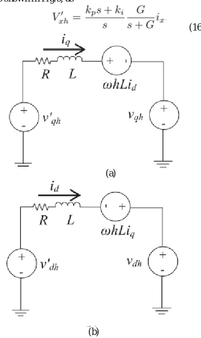
To design a PI controller for harmonic compensation, an approxi mate model for the equivalent system is derived in dqrotating reference frame, as shown
graphically in Fig.8. Thedifferential equations for the systems can be written as
(13) In the Laplace domain (12) and (13) can be written as
(14) (15) The transfer function can be expressed in ter ms of the PI controller (kp,ki) and harmonics estimation gain, G, as shown in Fig.5, as
(16)
(a)
(b)
Fig.8. Equivalent (a) q component (b) d component circuit for PI controller design.
V.INDUCTION MOTOR
Induction Motor (1M) An induction motor is an example of asynchronous AC machine, which consists of a stator and a rotor. This motor is widely used because of its strong features and reasonable cost. A sinusoidal voltage is applied to the stator, in the induction motor, which results in an induced electromagnetic field. A current in the rotor is induced due to this field, which creates another field that tries to align with the stator field, causing the rotor to spin. A slip is created between these fields, when a load is applied to the motor.
Compared to the synchronous speed, the rotor speed decreases, at higher slip values. The frequency of the stator voltage controls the synchronous speed [12]. The frequency of the voltage is applied to the stator through power electronic devices, which allows the control of the speed of the motor. The research is using techniques, which implement a constant voltage to frequency ratio. Finally, the torque begins to fall when the motor reaches the synchronous speed. Thus, induction motor synchronous speed is defined by following equation,
=
Where f is the frequency of AC supply, n, is the speed of rotor; p is the number of poles per phase of the motor. By varying the frequency of control circuit through AC supply, the rotor speed will change.
Fig.9.Speed torque characteristics of induction motor. VI.MATLAB/SIMULATION RESULTS
Fig 10 Matlab/simulation circuit of Conventional harmonic compensation method.
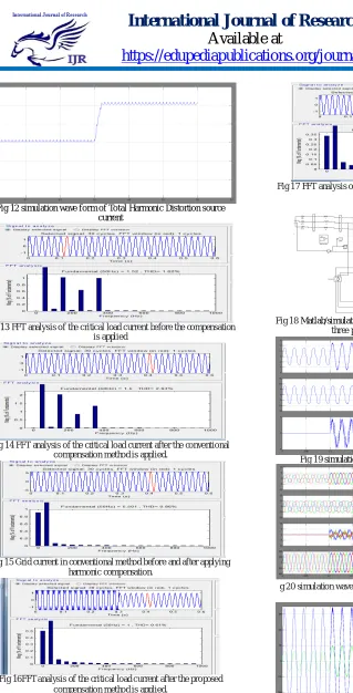
Fig 12 simulation wave form of Total Harmonic Distortion source current
Fig 13 FFT analysis of the critical load current before the compensation is applied
Fig 14 FFT analysis of the critical load current after the conventional compensation method is applied.
Fig 15 Grid current in conventional method before and after applying harmonic compensation.
Fig 16FFT analysis of the critical load current after the proposed compensation method is applied.
Fig 17 FFT analysis of the critical load current before the compensation is applied.
Fig 18 Matlab/simulation circuit of harmonic compensation method with three phase source industrial application
Fig 19 simulation wave form of voltage and current source
Fi g 20 simulation wave form of source and load current ,inverter current
and source voltage
VII.CONCLUSION
The power converter system integration with renewableenergy sources and interaction within a microgrid structure is presented with applicability in off grid islanded, grid-connected and genset-connected for residential and commercial installations. The system architecture presented incorporates DPG modules with flexible modes of operation in order to control the power flow for energy prioritization and syste m efficiency maximizationThe suggested placement of the harmonic reduction unit dictates the use of a special controller structure that uses the harmonics magnitude in the dqreference frame. An effective and efficient method is used to estimate the harmonics in the line. The proposed injects a voltage to counteract the harmonics in the system and reduce the THD to desired levels.An improved based harmonic elimination technique has been applied in this paper for control of induction motors and the various simulations has been performed on Simulink.
REFERENCES
[1].Saeed Anwar, Ali Elrayyah, and Yilmaz Sozer, Senior Member, IEEE”Efficient Single-Phase Harmonics EliminationMethod for Microgrid Operations”IEEE Transactions On Industry Applications, Vol. 51, No. 4, July/August 2015
[2] R. Erickson and D. Maksimovic, “Fundamentals of PowerElectronics,” 2nd Ed., Springer Science+Business, 2001, Ch.18. [3] C. Lascu, L. Asiminoaei, I. Boldea, and F. Blaabjerg, “Frequency Response Analysis of Current Controllers for Selective Harmonic Compensation in Active Power Filters,” IEEE Trans. Power Electron., vol. 56, no. 2, pp. 1826–1835, Feb. 2009.
[4] F. Blaabjerg, R. Teodorescu, M. Liserre, A. Timbus,”Overview of Control and Grid Synchronization for Distributed Power Generation Systems,” IEEE Trans. Ind. Electron., vol. 53, pp. 1398-1409, Oct. 2006. [5] M. Brenna, G.C. Lazaroiu, G. Superti-Furga, and E. Tironi, “Bidirectional Front End Converter for DG With Disturbance Insensitivity and Islanding-Detection Capability,“ IEEE Trans. Power Delivery, vol. 23, no. 2, pp. 907-914, April 2008.
[6] T. Kerekes, R. Teodorescu and U. Borup, “Transformer less Photovoltaic Inverters Connected to the Grid,” in Applied Power Electronics Conf., APEC 2007 - Twenty Second Annual IEEE, pp. 1733 – 1737, Feb. 2007-March 2007.
[7] M. Dai, M. Marwali, J. Jung, and A. Keyhani, “Power flow control of a single distributed generation unit,” IEEE Trans. Power Electron., vol. 23, no. 1, pp. 343–352, Jan. 2008.
[8] D. Ben Attous and Y. Bekakra, “Speed Control of a Doubly Fed Induction Motor using Fuzzy Logic Techniques”, International Journal of Electrical Engineering and Informatics, Vol. 2, No. 3, December 2010.
[9] M. D. Manjrekar, P. K. Steimer, and T. A. Lipo, “Hybrid multilevel power conversion system: a competitive solution for high-power applications,” IEEE Transactions on Industry Applications, vol. 36, pp. 834–841, May/June 2000
[10] Kennedy, James. "Particle swarm optimization." Encyclopedia of Machine Learning. Springer US, 2010. 760-766.
[11] Moradi, M. H., and M. Abedini. "A combination of genetic algorithm and particle swarm optimization for optimal DG location and sizing in distribution systems." International Journal of Electrical Power &Energy Systems 34.1 (2012): 66-74.
[12] Gandomi, Amir Hossein, et al. "Chaos-enhanced accelerated particle swarm optimization." Communications in Nonlinear Science and Numerical Simulation 18.2 (2013): 327-340.
[13] X. Yu and A. M. Khambadkone, “Combined active and reactive power control of power converter building block to facilitate the connection of micro-grid to Electric Power system,” in Proc. IEEE ECCE, 2009, pp. 1444–1450.
[14] M. Rahmatian, M. J. Sanjari, M. Gholami, and G. B. Gharehpetian, “Optimal control of distribution line series compensator in micro grid considering fault current limitation function,” in Proc. 17th Conf. EPDC, May 2012, pp. 1–5.
Author’s Profile:
B. Sreenivas received B.TECH degree from Raja Mahendra College Engineering & Technology (JNTUH) in the year 2011 and recived M.Tech in the stream of Electrical Power Engineering at Bharat Institute of Engineering &Technology(JNTUH).Currentl y working as a Assistant Professor in Scient Institute of Technology since 3 years and I am also the member of IJEEE. And his areas of interest are Power Syste ms, Electrical machines, Electrical Circuits and Control Systems.