Sri Krishna College of Engineering & Technology, Kuniamuthur, Coimbatore-641008, Tamilnadu, India
STATCOM with FLC and Pi Controller for a
Three-Phase SEIG Feeding Single-Phase
Loads
Ponananthi.V, Rajesh Kumar. B
Final year PG student,Department of Power Systems Engineering, M.Kumarasamy College of Engineering, Karur,
Tamilnadu, India
Assistant Professor, Department of Electrical and Electronics Engineering, M.Kumarasamy College of Engineering,
Karur, Tamilnadu, India
ABSTRACT: Induction generators are increasingly being used in non conventional energy systems. The self excited induction generators has some drawbacks such as poor voltage regulation, it requires reactive power source and while connecting non-linear loads the harmonics are injected. When single phase loads are connected to three-phase SEIG it cause unbalance in source current. The three-phase static synchronous compensator (STATCOM) connected at the point of common coupling (PCC) to compensate the unbalance current and to eliminate the harmonics. The hysteresis based control algorithm is used to generate the switching pulses to the STATCOM. The fuzzy controller is used instead of PI controller. The fuzzy logic controller gives better performance than conventional PI controller. This method is simulated using MATLAB/SIMULINK software. The simulated results shows that SEIG terminal voltage is maintained constant even with unbalanced loads using STATCOM based voltage regulation.
KEYWORDS: Self Excited Induction Generator (SEIG); single-phase synchronous D-Q frame theory; Static Synchronous Compensator (STATCOM).
І.INTRODUCTION
In remote areas, plenty of non-conventional energy sources are available. These non-conventional energy sources are used as prime input for the generating systems. Externally driven induction machine operates as a self-excited induction generator (SEIG) with its excitation requirements being met by a capacitor bank connected across its terminals. The SEIG has advantages like simplicity, maintenance free, absence of DC, brushless etc. as compare to the conventional synchronous generator.
Self-excitation phenomenon in induction machines although known for more than a half century. This induction generator is self excited by a suitable capacitor banks across the terminals. This phenomenon is known as capacitor self-excitation and the induction generator is called a “SEIG” [2]. A major disadvantage of SEIG is its poor voltage regulation requires a variable capacitance bank to maintain constant terminal voltage under varying loads.
ISSN (Online) : 2319 - 8753 ISSN (Print) : 2347 - 6710
I
nternationalJ
ournal ofI
nnovativeR
esearch inS
cience,E
ngineering andT
echnologyAn ISO 3297: 2007 Certified Organization, Volume 4, Special Issue 4, April 2015
National Conference on Trends in Automotive Parts Systems and Applications (TAPSA-2015) On 20th & 21st March
Organized by
Sri Krishna College of Engineering & Technology, Kuniamuthur, Coimbatore-641008, Tamilnadu, India
In this paper, the single phase linear and non-linear loads are connected to the three-phase SEIG which cause unbalance current and draws non-sinusoidal current due to non-linearity of load which injects harmonics into the system. The STATCOM is introduced to eliminates the harmonics, provides load balancing and supplies the reactive power and feeding single-phase loads using a three-phase SEIG without de-rating the machine. The transient analysis of the SEIG-STATCOM system under balanced/ unbalanced single-phase linear and non-linear loads and simulated results show that the SEIG-STATCOM system behaves an ideal supply under these unbalanced loads.
II. SELF EXCITED INDUCTION GENERATOR (SEIG)
Induction generator
The induction generators offer advantages over synchronous machines, resulting in a simplified installation with economy in first cost and in operating and maintenance expenses. The attractive feature of the induction generator is simplicity of operation.
Process of self excitation
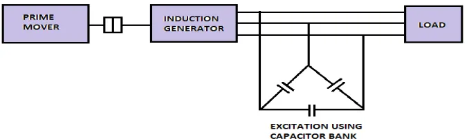
When an induction machine is driven at a speed greater than the synchronous speed then there will be negative slip. By means of an external prime mover, the direction of induced torque is reversed and it starts working as an induction generator. When the slip is negative then the induction machine draws a current, which lags the voltage by more than 90. This means that real power flows out of the machine but the machine needs the reactive power. To build up voltage across the generator terminals, excitations must be provided by two modes (i.e., grid connected and isolated mode). In case of a grid-connected mode, the induction generator can draw reactive power either from the grid but it will place a burden on the grid For an isolated mode, there must be a suitable capacitor bank connected across the generator terminals. This phenomenon is known as capacitor self-excitation and the induction generator is called a “SEIG.”
Figure 1: self excitation of induction generator
III. STATIC SYNCHRONOUS COMPENSATOR (STATCOM)
The static synchronous compensator is a shunt-connected reactive power compensation device which provides voltage support by generating or absorbing reactive power at the point of common coupling without the need of large external reactors or capacitor banks.
Modelling of control scheme of STATCOM
Sri Krishna College of Engineering & Technology, Kuniamuthur, Coimbatore-641008, Tamilnadu, India
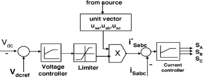
Figure 2: Block diagram of hysteresis current control technique
In three-phase balance system, the RMS voltage source amplitude is calculated at the sampling frequency from the source phase voltage (Vsa ,Vsb ,Vsc) and is expressed, as sample template Vsm, sampled peak voltage, as,
2 / 1 2 2 23
2
sa sb scsm
V
V
V
V
(1)The in-phase unit vectors are obtained from AC source phase voltage and the RMS value of unit vector as,
sm sa sa
V
V
u
;sm sb sb
V
V
u
;sm sc sc
V
V
u
(2) The in-phase generated reference currents are derived using in-phase unit voltage template as,
i
I
i
sa sa
.
*
;i
*sb
I
.
i
sb ;i
*sc
I
.
i
sc (3)Where I is proportional to magnitude of filtered source voltage for respective phases. This ensures that the source current is controlled to be sinusoidal. The unit vectors implement the important function in the grid connection for the synchronization for STATCOM. This method is simple, robust and favourable as compared with other methods.
The switching function for phase ‗a„ is expressed as
i
sa< (
i
sa*
-- HB) Sa = 0 (4)
i
sa> (
i
sa*
-- HB) Sa = 1 (5)
Where HB is a hysteresis current-band, similarly the switching function can be derived for phases b and c.
1) Hysteresis controller with PI voltage regulator
ISSN (Online) : 2319 - 8753 ISSN (Print) : 2347 - 6710
I
nternationalJ
ournal ofI
nnovativeR
esearch inS
cience,E
ngineering andT
echnologyAn ISO 3297: 2007 Certified Organization, Volume 4, Special Issue 4, April 2015
National Conference on Trends in Automotive Parts Systems and Applications (TAPSA-2015) On 20th & 21st March
Organized by
Sri Krishna College of Engineering & Technology, Kuniamuthur, Coimbatore-641008, Tamilnadu, India
Figure 3: STATCOM model with PI – Voltage Regulator block diagram
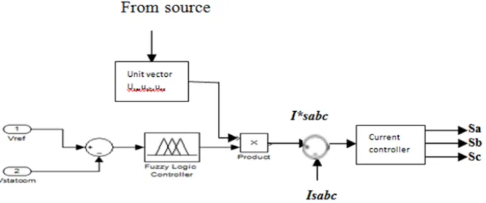
2) Hysteresis controller with Fuzzy logic
The fuzzy logic controller is fed by one input that is voltage error. This gives the reactive source current to the system as shown in figure 4.
Figure 4: STATCOM model with Fuzzy- Voltage Regulator block diagram
IV. SYSTEM CONFIGURATION AND PRINCIPLE OF OPERATION
Sri Krishna College of Engineering & Technology, Kuniamuthur, Coimbatore-641008, Tamilnadu, India
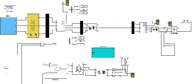
Figure 5: Block diagram of SEIG-STATCOM model
The STATCOM is employed to compensate the unbalanced currents caused by single-phase loads that are connected across the two terminals of the three-phase SEIG. Therefore, the SEIG is capable of feeding single-phase loads up to its rated power. The STATCOM acts as a source of lagging or leading current to maintain the constant terminal voltage with variation in load. Moreover, the STATCOM suppresses harmonics injected by nonlinear loads and provides load balancing while feeding single-phase loads. The STATCOM consists of a two- level, three-phase IGBT based current controlled voltage source inverter and DC bus capacitor.
For simulation a 3.7-kW, 230-V, 50-Hz, Y-connected induction generator has been used to investigate the performance while feeding single-phase loads. A Δ-connected 4-kVAR capacitor bank is connected across the induction generator terminals to provide self-excitation and a induction motor having 3.7-kW, 415-V, 50-Hz, Y-connected is used to drive the SEIG. A three-phase two-level IGBT based VSI has been used as the STATCOM. The STATCOM is connected across the PCC through filter inductors. Both linear and nonlinear loads are considered for testing the system. A single-phase uncontrolled diode bridge rectifier feeding a series R-L load is used as a nonlinear load.
V. RESULTS AND DISCUSSION
The three-phase self excited induction generator feeding single-phase linear and non-linear loads with STATCOM is simulated using MATLAB/simulink software as shown in figure 6. While connecting single phase loads the THD value of the source current using FFT analysis without STATCOM are shown in figure 7.
ISSN (Online) : 2319 - 8753 ISSN (Print) : 2347 - 6710
I
nternationalJ
ournal ofI
nnovativeR
esearch inS
cience,E
ngineering andT
echnologyAn ISO 3297: 2007 Certified Organization, Volume 4, Special Issue 4, April 2015
National Conference on Trends in Automotive Parts Systems and Applications (TAPSA-2015) On 20th & 21st March
Organized by
Sri Krishna College of Engineering & Technology, Kuniamuthur, Coimbatore-641008, Tamilnadu, India
Figure 7: FFT analysis of source current waveform without STATCOM
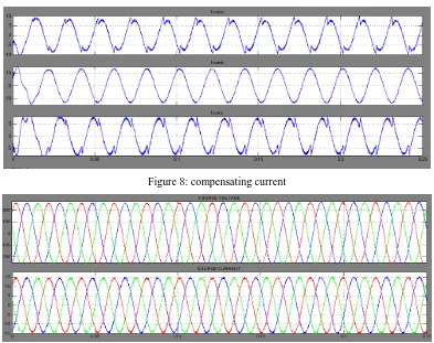
The compensating currents are generated as using the STATCOM to balance the unbalanced current caused by single phase loads and to reduce harmonics. The switching pulse generated is given to the three-phase two level IGBT based voltage source inverter. STATCOM absorbs or generate reactive power and in which the output can be varied to control the specific parameters of an electric power system. Figure 8 shows the compensating currents at the point of common coupling. The icoma, icomb, icomc are the compensating current to regulate the terminal voltage of the SEIG. The PCC voltage is found very stable and well regulated during the load perturbation. After the compensating currents the source current is balanced in the system. Figure 9 shows the source current and voltage after compensation.
Figure 8: compensating current
Sri Krishna College of Engineering & Technology, Kuniamuthur, Coimbatore-641008, Tamilnadu, India
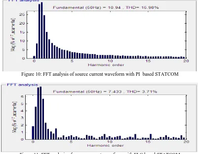
The figure 7 and 10 shows the harmonic suppression from 26.92% to 2.92% when connecting STATCOM controller with PI. The figure 11 shows the THD value of source current from the FFT analysis with FLC based STATCOM, it is observed that the THD of the source current waveform of the test system with FLC based STATCOM is 1.42 %. Thus, it is observed that there is a further reduction in the THD value of the source current waveform.
Figure 10: FFT analysis of source current waveform with PI based STATCOM
Figure 11: FFT analysis of source current waveform with FLC based STATCOM
VI. CONCLUSION
The proposed method of feeding single-phase loads from a three-phase SEIG with STATCOM combination has been tested, and it has been proved that the SEIG is able to feed single-phase loads up to its rated capacity. Hysteresis based Fuzzy controller of a three-phase STATCOM has been proposed, discussed, and experimentally implemented for current balancing of the SEIG system. From the simulated results, it is found that SEIG terminal voltage remains constant and sinusoidal feeding the three-phase or single-phase rectifiers with R and R-L loads. The proposed FLC based STATCOM have improved the power quality of source current significantly by reducing the THD from 26.92% to1.42 %. It is clearly presented that STATCOM with FLC gives better performance than STATCOM with conventional PI controller. Therefore, it is concluded that STATCOM acts as voltage regulator, load balancer and also harmonic eliminator.
ACKNOWLEDGMENT
ISSN (Online) : 2319 - 8753 ISSN (Print) : 2347 - 6710
I
nternationalJ
ournal ofI
nnovativeR
esearch inS
cience,E
ngineering andT
echnologyAn ISO 3297: 2007 Certified Organization, Volume 4, Special Issue 4, April 2015
National Conference on Trends in Automotive Parts Systems and Applications (TAPSA-2015) On 20th & 21st March
Organized by
Sri Krishna College of Engineering & Technology, Kuniamuthur, Coimbatore-641008, Tamilnadu, India REFERENCES
[1] Bhim Singh, Fellow, IEEE, S. S. Murthy, Life Fellow, IEEE, and Raja Sekhara Reddy Chilipi, “STATCOM-Based Controller for a Three-Phase SEIG Feeding Single-Phase Loads”, IEEE transactions on energy conversion, vol. 29, no. 2, june 2014.
[2] C. Bansal, Senior Member, IEEE , “Three-phase self -excited induction generator : An overview,” IEEE transactions on energy conversion, vol. 20, no. 2, june 2005.
[3] Dhikra Chermiti, Adel Khedher, “A New Method Voltage and Frequency Regulation of Self-Excited ” wseas transactions on environment and
development Induction Generator Operating in Stand Alone
[4] G. Dastagir and L. A. C. Lopes, “Voltage and frequency regulation of a stand-alone self-excited induction generator,” in Proc. IEEE Electr.
Power Conf., 2007, pp. 502–506.
[5] H. Rai, A. Tandan, S. Murthy, B.Singh, and B. Singh, “Voltage regulation of self excited induction generator using passive elements,” in Proc.
IEEEInt. spp. 240– 245.
[6] L. Shridhar, B. Singh, and C. Jha, “Transient performance of the self regulated short shunt self excited induction generator,” IEEE Trans.
EnergyConvers., vol. 10, no. 2, pp. 261–267, Jun. 1995.
[7] E. Bim, J. Szajner, and Y. Burian, “Voltage compensation of an induction generator with long-shunt connection,” IEEE Trans. Energy Convers., vol. 4, no. 3, pp. 526–530, Sep. 1989.
[8] L. Shridhar, B. Singh, C. Jha, B. Singh, and S. Murthy, “Selection of capacitors for the self regulated short shunt self excited induction generator,” IEEE Trans. Energy Convers., vol. 10, no. 1, pp. 10–17, Mar. 1995.
[9] L. Wang and C.-H. Lee, “Long-shunt and short-shunt connections on dynamic performance of a SEIG feeding an induction motor load,” IEEE
Trans. Energy Convers., vol. 15, no. 1, pp. 1–7, Mar. 2000.
[10] M. B. Brennen and A. Abbondanti, “Static exciters for induction generators,” IEEE Trans. Ind. Appl., vol. IA-13, no. 5, pp. 422–428, Sep. 1977. [11] B. Singh, S. Murthy, and S. Gupta, “STATCOM-based voltage regulator for self-excited induction generator feeding nonlinear loads,” IEEE
Trans. Ind. Electron., vol. 53, no. 5, pp. 1437–1452, Oct. 2006.
[12] E. Larsen, N. Miller, S. Nisson and S. Lindgren, "Benefits of GTO based compensation systems for electric utility applications," IEEE Trans, on
Power Delivery, Vol. 7, No. 4, pp. 2055-2064, October 1997.
[13] C. Schauder and H. Mehta, "Vector analysis and control of advanced static VAR compensator," IEE Proc.-C, Vol. 140, No. 4, pp.299-306, July 1993.
[14] T. Chan and L. L. Lai, “A novel single-phase self-regulated self-excited induction generator using a three-phase machine,” IEEE Trans. Energy
Convers., vol. 16, no. 2, pp. 204–208, Jun. 2001.s