Validation of Nonrigid Image Registration Using
Finite-Element Methods: Application to
Breast MR Images
Julia A. Schnabel*, Christine Tanner, Andy D. Castellano-Smith, Andreas Degenhard, Martin O. Leach,
D. Rodney Hose, Derek L. G. Hill, Member, IEEE, and David J. Hawkes
Abstract—This paper presents a novel method for validation of
nonrigid medical image registration. This method is based on the simulation of physically plausible, biomechanical tissue deforma-tions using finite-element methods. Applying a range of displace-ments to finite-element models of different patient anatomies gen-erates model solutions which simulate gold standard deformations. From these solutions, deformed images are generated with a range of deformations typical of those likely to occur in vivo. The regis-tration accuracy with respect to the finite-element simulations is quantified by co-registering the deformed images with the orig-inal images and comparing the recovered voxel displacements with the biomechanically simulated ones. The functionality of the val-idation method is demonstrated for a previously described non-rigid image registration technique based on free-form deforma-tions using B-splines and normalized mutual information as a voxel similarity measure, with an application to contrast-enhanced mag-netic resonance mammography image pairs. The exemplar non-rigid registration technique is shown to be of subvoxel accuracy on average for this particular application. The validation method pre-sented here is an important step toward more generic simulations of biomechanically plausible tissue deformations and quantifica-tion of tissue moquantifica-tion recovery using nonrigid image registraquantifica-tion. It will provide a basis for improving and comparing different non-rigid registration techniques for a diversity of medical applications,
Manuscript received September 12, 2001; revised October 23, 2002. The work on biomechanical tissue modeling using ANSYS was supported by the EPSRC. The work of J. A. Schnabel was supported by EasyVision Advanced Development, Medical Imaging Information Technology (MIMIT), Philips Medical Systems, Best, The Netherlands. The work of C. Tanner was supported by the EPSRC under Grant GR/M52779 and Grant MIAS-IRC. The work of A. D. Castellano-Smith was supported by the EPSRC under Grant GR/M47294. The work of A. Degenhard was supported by the EPSRC under Grant GR/M52762. The Associate Editor responsible for coordinating the review of this paper and recommending its publication was M. Giger. Asterisk
indicates corresponding author.
*J. A. Schnabel is with the Computational Imaging Sciences Group, Division of Imaging Sciences, Guy’s, King’s and St. Thomas’ School of Medicine, King’s College London, London SE1 9RT, U.K. (e-mail: [email protected]).
C. Tanner, A. D. Castellano-Smith, D. L. G. Hill, and D. J. Hawkes are with the Computational Imaging Sciences Group, Division of Imaging Sciences, Guy’s, King’s and St. Thomas’ School of Medicine, King’s College London, London SE1 9RT, U.K.
A. Degenhard was with the CRC Clinical MR Research Group, The Institute of Cancer Research and the Royal Marsden NHS Trust, Sutton, Surrey SM2 5PT, U.K. He is now with the Faculty of Physics, University of Bielefeld, 33615 Bielefeld, Germany.
M. O. Leach is with the CRC Clinical MR Research Group, The Institute of Cancer Research and the Royal Marsden NHS Trust, Sutton, Surrey SM2 5PT, U.K.
D. R. Hose is with the Clinical Sciences Division, Department of Medical Physics and Clinical Engineering, Royal Hallamshire Hospital, University of Sheffield, Sheffield S10 2JF, U.K.
Digital Object Identifier 10.1109/TMI.2002.808367
such as intrasubject tissue deformation or motion correction in the brain, liver or heart.
Index Terms—Biomechanics, breast MR imaging, finite element
methods, image registration, validation.
I. INTRODUCTION
I
MAGE registration describes the process of establishing spatial correspondence between features in an image pair, or a dynamic or temporal sequence of images, in order to relate them for diagnosis, inspection of homologous positions, or temporal monitoring. The images might be acquired using the same or different imaging modalities, and can also be aligned to a computer model, or to locations in physical space for image guidance. Feature alignment is described by a transforma-tion, which, for rigid-body registratransforma-tion, describes differences in global patient positioning. For nonrigid registration, the transformation explains additional deformations due to soft tissue properties, surgical intervention, temporal changes due to tumor growth or radiotherapy treatment, and morphological differences between individuals. Also, nonrigid registration can compensate for geometric image distortion caused by the acquisition technique. There is a consensus in the literature that registration is needed to compensate for patient positioning and deformation. Various registration algorithms have been proposed, surveys of which can be found in [1]–[5]. Prior to clinical use, registration techniques need to be validated. However, validation of registration performance suffers from the lack of knowledge as to if, how much, and where patient movement has occurred between and even during scanning procedures, and whether such movement affects the clinical usefulness of the data. To maintain clinical usefulness, and inherently improve patient treatment and health care, it is, therefore, mandatory to ensure that registration is successful. How the success of medical image registration can be assessed and failure can be detected is laid out in a recent survey by Fitzpatrick [6], and will be discussed with an emphasis on validation of nonrigid registration in the following.As a first step, a registration method can be assessed in an independent evaluation in the absence of a ground truth. An ini-tial visual inspection allows for a qualitative assessment of reg-istration performance, which can be complemented by quanti-tative checks for robustness and consistency. The former estab-lishes the measurement precision by testing the bias sensitivity when adding noise or choosing different starting estimates [7].
The latter assesses the capability of a registration technique to find circular transformations based on a registration circuit, but can be sensitive to bias and may not be applicable to nonin-vertible transformations generated by many nonrigid registra-tion methods. Nonetheless, consistency checks have been suc-cessfully used for intramodality rigid body registration applica-tions, e.g., for serial magnetic resonance (MR) imaging of the brain [8].
As a second step, the registration outcome can be judged and ranked by expert observers using visual assessment techniques in a large study. This can involve the inspection of subtraction images, contour or segmentation overlays, alternate pixel dis-plays, or viewing anatomical landmarks. These approaches have been applied to rigid registration [9], and since they involve in-spection of the entire volume domain of the image pair, can be extended to nonrigid registration [10]. Visual assessment is an important step toward clinical acceptance and routine use of a registration method, but may be compromised for nonrigid reg-istration by locally implausible deformations which may not be readily picked up by observers [11].
As a third step, quantitative measures assessing the accuracy of a registration method can be performed. Accuracy, however, can only be measured if a ground truth is available. Maintz and Viergever [3] argue that if such ground truth techniques existed, they should be used for the registration in the first place. Nonetheless, registration accuracy can be studied while keeping the error bounds in mind. The main approach for estimating accuracy involves establishing a gold standard. For example, the retrospective registration evaluation project [12] used skull-implanted markers in patients undergoing brain surgery to derive a gold standard transformation for multimodality rigid-body image registration of the head to compare different established registration methods. For non-rigid registration validation, extrinsic markers could be attached to the skin surface or implanted into deformable tissue. Skin markers have the advantage of not being invasive, but suffer from movement related to skin mobility, and from being far from more internal, relevant anatomical structure. Implanted markers are highly invasive and, therefore, can only be used if a patient is undergoing surgery. At any rate, such markers may not provide a sufficiently dense displacement field for nonrigid registration validation. This is also true for intrinsic markers like anatomical landmarks, which are often too sparse and too difficult to localize accurately. As an alternative, physical phantoms or cadavers with densely distributed markers could be used, but they cannot be easily deformed in a controlled manner, nor are accuracy measures obtained in vitro readily transferable to in vivo applications. As an alternative to markers, a gold standard registration system can be used to simulate “ground truth” transformations against which transformations obtained from registration can be compared [6]. For nonrigid motion simulation, the most common approach is to displace a set of landmarks and interpolate a dense displacement map using thin-plate splines or other interpolants (e.g., [13]). The landmarks may be anatomical or geometric, or corresponding to intersections of a regular grid superimposed on the image. Such simulations commonly ignore the underlying tissue properties, which may lead to physically and biomechanically unrealistic deformation simulations. Moreover, in many cases the same or a similar displacement interpolant is used in the
subsequent registration process, which could introduce a bias of the validation toward the registration method.
Finally, there are more practical validation issues to con-sider. For example, Maintz and Viergever [3] list resource
requirements and algorithmic complexity, which refer to
preparations required for the registration (such as segmentation of structures, or landmark extraction), and computational time constraints for use in clinical practice, respectively. Automated registration methods can help to fulfill such requirements, and, with computing power improving, the run-time of registration algorithms continues to decrease.
The validation steps described above highlight a number of unresolved research issues for nonrigid registration validation. In this paper, we address the simulation of gold standard defor-mations to measure nonrigid registration accuracy. We present a novel biomechanically motivated validation methodology which is based on modeling tissue properties and simulating tissue deformations using finite-element methods (FEMs). Earlier work on this technique was presented by us in [14]. This simulation comprises a range of physically plausible tissue deformations which are most likely to happen in clinical practice and, hence, provides more insight into the reliability of the registration, i.e., the behavior of the algorithm to be expected in a real clinical setting for reasonable clinical input [3]. The accuracy of the registration can be established via a complete, dense map of simulated voxel displacements. We apply this validation method to a previously described nonrigid registration algorithm by Rueckert et al. [15] for contrast-en-hanced (CE) MR mammography. Although the validation method is applied here to a specific algorithm and clinical application, it describes a generic methodology for validating nonrigid registration algorithms. This methodology requires FEM modeling of the target anatomy but may be applied to a variety of registration tasks, e.g., motion or deformation correction in the brain, liver or heart. The purpose of this paper is to present the concept of the validation framework using an exemplar registration technique and application. It is designed for intrasubject registration tasks, where tissue deformation with respect to a subject’s anatomy and an assumed material model can be simulated using biomechanical modeling. Inter-subject registration validation using deformation simulations is an even more challenging task, as this would also require a model of anatomical variability, which has so far only been attempted using statistical models of variation [16], [17].
The remainder of this paper is organized as follows: Sec-tion II briefly describes the exemplar nonrigid registraSec-tion method used, and Section III describes the breast tissue modeling using FEMs. Section IV presents the simulation of biomechanical deformations in breast tissue, and Section V summarizes the registration accuracy measurements obtained. Finally, Section VI summarizes the presented validation methodology, outlines the potential for further improvement, and concludes this paper.
II. NONRIGIDREGISTRATION
on free-form deformations using B-splines, and uses normal-ized mutual information as a voxel-similarity measure [18]. It models global patient motion using an affine transformation, followed by modeling local motion by manipulating an under-lying mesh of B-spline control points. The combined global and local motion model at each image point is ex-pressed as
(1)
The flexibility and computational complexity of the local mo-tion model is related to the choice of control point spacing. The algorithm makes no assumption about the underlying material properties of the different tissue types in the breast.
In a visual assessment study, the algorithm was shown to sig-nificantly improve the image quality of the subtraction images for a large MR mammography database [10]. For this applica-tion, patient movement as well as tissue deformation often occur during dynamic scanning due to patient reaction to contrast in-jection, contraction and relaxation of the pectoral muscles, as well as movement against the scanner radio-frequency (RF) coil. As tumors are often only clearly seen on subtraction images, any misalignment may render enhanced tumors indistinguishable from surrounding bright motion artefacts. Recently, we have found that this algorithm can cause volume changes in regions of enhanced lesions in MR mammography [11]. These volume changes may occur due to the similar intensity of fatty tissue and CE fibroglandular tissue, but are physically unlikely given the incompressibility of the breast tissue, and the short acqui-sition time of the dynamic image sequence. There is, therefore, a need to further investigate the behavior and accuracy of this algorithm using simulations of patient motion in CE MR mam-mography.
III. FINITE–ELEMENTMODELING OF THEBREAST
A. Background
The modeling of biomechanical tissue properties has gained considerable interest in a range of clinical and research ap-plications. FEMs can be used to model the interrelation of different tissue types by applying displacements or forces. This can help to predict mechanical or physical deformations during surgical procedures, and to derive and quantify tissue properties from observed deformations. For example, FEMs for brain modeling have been investigated for model updating of image guided surgery procedures [19]–[21], for integration into physically based nonrigid registration methods [22], and for simulation of brain shift in interventional MR imaging [23]. For mammography, FEMs have been explored for predicting mechanical deformations during biopsy procedures [24], for simulating compressions similar to X-ray mammography in MR mammography [25], for improving and testing the reconstruction of elastic properties in elastography [26]–[28], and for modality-independent elastography with application to breast imaging [29].
B. Materials
From a database of previously acquired dynamic sequences of Gadolinium DTPA (Gd-DTPA)-enhanced MR mammog-raphy volumes of 42 patients with histologically confirmed
Fig. 1. Two-dimensional example slices, subtractions, and maximum intensity projections (MIPs) of subtraction volumes for three MR breast volumes. (from left to right) Patient cases 1–3. (from top to bottom) Precontrast image, postcontrast image, subtraction image, and MIP.
carcinoma, three patient cases were selected. All data were acquired on a Philips 1.5-T Gyroscan ACS2 using a fast 3-D
gradient echo sequence with ms, ms, 35
flip angle, 350-mm field of view (FOV), and axial (transversal) slice orientation. A dynamic sequence of one scan before, and five scans after contrast injection of 0.2-mmol Gd-DTPA/kg of body weight at temporal intervals of 1 min was acquired. For the purpose of this paper, we have selected the precontrast scan and the second postcontrast scan of the three patients. The images have dimensions of 256 256 25 voxels with an in-plane voxel size of 1.37 mm 1.37 mm (cases 1 and 2) and 1.48 mm 1.48 mm (case 3), all with 4.2-mm slice thickness. From each data set, we have extracted a volumetric cuboid region of interest (ROI) containing one breast for each patient. Both the anatomy and pathology of the selected cases are substantially different, with the overall breast volume ranging from 0.66 10 mm (case 1) to 1.23 10 mm (case 3), with tumor volumes between 235.52 mm (case 1) and 3061.75 mm (case 3).
shows two-dimensional (2-D) example slices through the ROIs of the image pairs and image subtractions, as well as maximum intensity projections (MIPs) through the subtraction volumes. From the subtraction images as well as the MIPs one can ap-preciate the negligible amount of motion between precontrast and postcontrast scans within the breast tissue, and motion arte-facts due to breathing and cardiac motion at the chest wall. The tumors and some enhanced blood vessels become clearly vis-ible within the subtraction images and MIPs. Nonrigid registra-tion confirmed almost no moregistra-tion for the original image pairs: mean tissue displacements within the breast tissue, excluding the tumor region, were estimated to be within 1 mm (case 1), 0.36 mm (case 2), and 0.55 mm (case 3). Within the tumor re-gions, mean tissue displacements of 0.45 mm (case 1), 0.68 mm (case 2), and 0.40 mm (case 3) were found. Having selected image pairs with only little motion enables us to simulate motion between the original, uncorrected precontrast and postcontrast scans.
C. Model Construction
For the construction of finite-element models for the three cases, the first step is to obtain tissue segmentations. For this, the ANALYZE software package [30] was used to segment fatty and fibroglandular tissue in the CE images. The tumors were segmented in the subtraction images, which was made possible due to the negligible amount of motion between scans.
As the second step, we have constructed for the three cases isotropic, linear, and nearly incompressible elastic models incorporating skin surface, fat, fibroglandular, and tumorous tissue. For this purpose, we have performed 3-D triangula-tions of the tumors and the overall breast tissue (excluding the tumorous tissue) using standard marching cubes and decimation techniques provided by the Visualization Toolkit [31], with minimal edge lengths of 4.2 mm (corresponding to the slice thickness) for tumorous tissue and 8.4 mm for the remaining tissues. Using the ANSYS FEM software package,1
the triangulations were meshed into isoparametric tetrahedral structural solids (elements), having four corner FEM nodes2
and an additional FEM node in the middle of each edge for a quadratic displacement behavior. Each FEM element was labeled corresponding to the underlying tissue type. Skin was modeled by adding 1-mm-thick triangular shell elements consisting of six FEM nodes onto the surface of the fatty tissue. The models contain 40 172 (case1), 117 436 (case 2), and 118 278 (case 3) FEM nodes, arranged in 30 841 (case 1), 89 094 (case 2), and 89 944 (case 3) elements, including the surface shells. Each FEM node has three associated degrees of freedom which define translational displacement in the , , and directions.
As the third and final step in the model construction, material properties for the different tissue types were chosen from the literature. The Young’s moduli (stress–strain relations) of the different tissues were set to 1 kPa for the fatty tissue, 10 kPa for the fibroglandular tissue, and 16.5 kPa for the tumorous carcinoma [32]. A Young’s modulus of 88 kPa was chosen for
1Available: http://www.ansys.com
2To avoid any confusion with anatomical tissue nodes in the pectoral breast
region, or the B-spline control points used in the registration, we will refer to the nodes of the FEM elements as FEM nodes in the remainder of this paper.
Fig. 2. Breast segmentations and FEM model renderings for patient cases shown in Fig. 1. (from top to bottom) Patient cases 1–3. (from left to right) Example slices for segmentations into fat (dark grey), fibroglandular tissue (light grey), and tumor (white); wire-frame cuts through FEM models with material labels in the same color code; mesh surface renderings of FEM models. The wire-frame cuts show the higher mesh resolution within tumor locations.
the skin, representing a linear approximation of the nonlinear stress–strain curve for abdominal skin parallel to the cranio-caudal median investigated by Park [33] for strains up to 30%. For near-incompressibility of the tissue, the Poisson’s ratio was set to 0.495.
The aim of this study is to obtain approximate breast models which can produce physically plausible deformations, rather than to build optimal, patient-specific models. This allows the generation of a generic image class for registration val-idation. For more realistic breast modeling, patient-specific model parameters would need to be determined from in vivo elastographic measurements. However, the models described above can be varied further with respect to material properties, nonlinear or even anisotropic tissue characteristics, in order to simulate different patient characteristics. Fig. 2 shows example slices through the tissue segmentations, material-labeled wire-frame renderings as well as surface renderings of the three breast models.
IV. SIMULATION OFGOLDSTANDARDBREASTDEFORMATIONS
A. Finite-Element Model Solutions
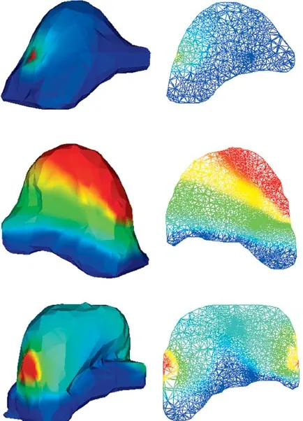
Fig. 3. Surface and wire-frame renderings of example solutions for models shown in Fig. 2. (from top to bottom) Patient cases 1–3, for point puncture (case 1), regional displacement (case 2), and two-sided contact (case 3). (left) Surface renderings of deformed meshes. (right) Wire-frame cuts through deformed meshes. Deformation magnitudes are mapped using rainbow color coding, with dark blue corresponding to 0 mm, and dark red corresponding to 10-mm deformation magnitude.
breast model, the following four deformation types character-istic for real patient acquisitions were applied.
• Regional displacement simulates a uniform surface dis-placement by translating a set of surface FEM nodes. • Point puncture displaces a single surface FEM node which
simulates a very localized displacement, e.g., as occurring during a biopsy without any breast fixation.
• One-sided contact displaces surface FEM nodes on one side onto a plane, which simulates the deformation of the breast when moving against the scanner RF coil, assuming no sliding on the plane itself.
• Two-sided contact analogously models the deformation when the breast is fixed at both sides, by displacing sur-face FEM nodes onto a plane on each side.
Thus, we have obtained 12 deformation simulations (three breast models with four deformation simulations each). For more exhaustive deformation simulations, additional simula-tions can be performed by varying the type, magnitude, and locality of the boundary conditions. In all simulations, the FEM
nodes adjacent to the deep pectoral fascia have been fixed,
assuming no movement of the pectoral muscle and pectoral fascia. Fig. 3 shows surface renderings of and wire-frame cuts through the patient models for example FEM solutions, with local deformation magnitudes mapped in rainbow color coding.
B. FEM Displacements
Each FEM solution yields a displacement vector at each FEM node within the model. The average displacement of the whole breast volume and within individual tissue compartments can be obtained by integrating over all displacement vectors
(2)
where is the number of FEM nodes in the model or of indi-vidual tissue compartments.
For an image voxel (or subvoxel) location not coinciding with a FEM node location, but lying anywhere within a FEM element, a numerically exact displacement can be in-terpolated by weighting the element’s ten FEM node displace-ments by their quadratic shape function [34]
(3)
Hence, a dense displacement interpolation for all image voxels can be obtained, and integrated over all voxel locations within the breast volume or within individual tissue compartments to find the average displacement
(4)
where is the number of voxels over which this measure is computed.
Fig. 4 shows the average and maximum node and interpolated voxel displacements for all patient solutions within the whole breast volume as well as only within the tumorous tissue. The maximum displacements are around 10 mm, mostly occurring in fatty tissues close to the skin surface. A higher mean displace-ment within the tumors occurs for cases 2 and 3, where the tu-mors are located close to the initially displaced skin surface.
C. Interpolation of FEM Solutions
Fig. 4. Mean and maximum FEM node and interpolated voxel displacements of different FEM solutions for the three patient cases, computed within whole breast tissue (left) and within tumorous tissue (right). (top) FEM node displacements. (bottom) FEM shape-interpolated voxel displacements.
To avoid any simulation inconsistencies, we instead employ the accurate FEM shape interpolation defined in (3). This inter-polation removes any residual bias of the validation method to-ward the motion model used by the registration method. Based on the dense displacement fields within the breast tissue, the image intensities are interpolated using a truncated sinc inter-polation kernel [36]. It is important to note that since by defi-nition no voxel displacements occur at locations outside of the model, these locations need to be masked out in the deformed images and excluded from any further processing and analysis. For this reason, and to avoid any further intensity interpolation of the simulated image volumes during registration, the FEM deformed images become the reference (or target) image vol-umes, and the original, undeformed and unmasked images are the transform (or source) image volumes for the subsequent reg-istration process. If an image volume is to be registered against a FEM deformed version of itself, the noise field of the FEM deformed image is changed by adding Rician distributed noise with a standard deviation corresponding to the noise distribution in the original image background.
The original postcontrast images of the three patient cases were deformed with respect to the four FEM solutions and asso-ciated dense displacement interpolations. Fig. 5 shows example slices through the FEM deformed postcontrast images of the three patients for the three example solutions shown in Fig. 3.
Fig. 5. Slices of example FEM deformation simulations of postcontrast image volumes. (from left to right) Patient cases 1–3, for point puncture (case 1), regional displacement (case 2), and two-sided contact (case 3). Compare with original postcontrast image slices in Fig. 1.
V. EXPERIMENTS ANDRESULTS
A. Experiments
To demonstrate the potential of the proposed validation scheme, we have applied it to test the exemplar nonrigid registration algorithm described in Section II with a control point resolution of 10 mm as a sensible choice, given the expected maximum displacements of 10 mm imposed by the FEM boundary conditions. Another motivation for using this particular resolution is that it was successfully used in the visual assessment study on the same data [10].
by registering the original postcontrast images to a deformed version of themselves. A more realistic setting, where patient motion or deformation has occurred between precontrast and postcontrast scans, is then simulated by registering the original precontrast images to the FEM deformed postcontrast images. This approach is based on the reasonable assumption that for the selected patient cases, actual motion between the original precontrast and postcontrast images was negligible.
The registration accuracy can then be assessed either at the
FEM node positions [using of (2)], or over the entire
in-terpolated displacement field within the warped breast volumes [using of (4)]. The latter is more consistent in the sense that it provides a denser sampling of displacements for accuracy measurements, in view of the scattered distribution of the FEM
nodes. The residual registration error for a given transformation
[as defined by (1)] is then defined for all tissue locations or subsets thereof as
(5)
where is the number of voxels at which the error measure is calculated.
B. Postcontrast-to-Postcontrast Image Registration Accuracy
Fig. 6 illustrates example 2-D slices for the three patient cases through the subtracted images volumes before and after registra-tion of the postcontrast images to the FEM deformed versions of themselves, with the difference of artificially added Rician distributed noise in the warped images. Before registration, a considerable amount of deformation imposed by the FEM so-lutions near to the skin surface, and to a lesser degree within the breast tissues, can be observed. Ideally, after registration the subtraction images should contain only the added noise. Fig. 6 shows that the deformations are mostly recovered within the breast tissue after registration, with remaining localized misreg-istrations only near the skin surface, and at the edge of the FOV. The residual average and maximum registration errors ac-cording to (5) for the postcontrast registration experiment are shown in the top row of Fig. 9. The average registration error is about 0.4 mm, with maximum errors between 2.4 mm and up to 10 mm. These maximum errors were found to be very localized near the edge of the FOV and the displaced skin surface. When investigating the registration accuracy within the tumorous tis-sues separately, the average error for the postcontrast registra-tion experiment is very low and lies around 0.17 mm, with only a small maximum error of up to 0.45 mm.
C. Precontrast-to-Postcontrast Image Registration Accuracy
The clinically more realistic and relevant experiment of reg-istering the original precontrast images to FEM deformed post-contrast images investigates how well simulated patient motion between precontrast and postcontrast acquisitions can be recov-ered by registration. The subtraction slices in the top row of Fig. 7 show that the tumors are barely visible before registration, and cannot be clearly distinguished from the surrounding bright motion artefacts. However, after registration, these motion arte-facts have been mostly removed, apart from localized areas near the skin surface (bottom row of Fig. 7). Fig. 8 shows additional
Fig. 6. Example subtraction slices of original postcontrast images from example FEM deformation simulations before (top) and after (bottom) registration. From left to right: Patient cases 1–3, for point puncture (case 1), regional displacement (case 2), and two-sided contact (case 3).
Fig. 7. Example subtraction slices of original precontrast images from example FEM deformation simulations before (top) and after (bottom) registration. (from left to right) Patient cases 1–3, for point puncture (case 1), regional displacement (case 2), and two-sided contact (case 3). Compare with original subtraction slices in Fig. 1.
Fig. 9. Mean and maximum registration error for the registration of the original image pairs to FEM deformation simulations for the three patient cases, computed as mean voxel displacements in the whole breast volume (left) and in tumorous tissue (right). (top) registration of original postcontrast images to FEM deformed postcontrast images. (bottom) Registration of original precontrast images to FEM deformed postcontrast images.
MIPs through the subtraction volumes before and after registra-tion. Although the registered subtraction images and MIPs are not directly comparable to the original subtraction images and MIPs in Fig. 1, as they are defined in the coordinate system of the FEM deformed images rather than the original images, they appear to be of a similar quality.
The bottom row of Fig. 9 shows the residual average and max-imum registration errors for the precontrast image registration according to (5). The average registration error is slightly higher (0.85 mm) than for the postcontrast image registration described in Section V-B, with maximum errors between 2.86 mm and up to 10 mm, which were also found to be localized outliers near the skin surface. Within the tumorous tissue, the average error within the tumors is slightly higher than in the whole breast tissue (0.97 mm), and the maximum errors are between 0.53 mm and 2.93 mm, with the larger errors mainly occurring for patient 2 where the tumor lies close to the displaced skin surface. This higher error in the tumor region may also be an indication for the hypothesis that in CE image pairs, tumor volume is not suf-ficiently preserved by the nonrigid registration algorithm [11]. This may result in a very localized misregistration which now can be quantified with the presented validation methodology.
In summary, the registration accuracy for the registration method investigated using FEM simulations is slightly higher when registering the postcontrast image volumes to a FEM
deformed version of themselves, than for registration of the precontrast to the FEM deformed postcontrast images. This is not surprising as there may remain a small amount of patient motion between the original, undeformed image pairs, which should be recovered by the registration and, thus, is quantified as a registration error. Both registration scenarios show very localized maximum errors at the skin surface. This error may be due to the masking of the FEM deformed breast images, leading to a local, sharp discontinuity of the simulated deformation field (in particular for the plate contact solutions). Smooth deformation interpolants such as the B-spline interpolation in the registration used in this paper may not compensate for this at the chosen control point resolution.
VI. DISCUSSION
A. Summary
range of data, based on different patient anatomies and deforma-tion simuladeforma-tions, the validadeforma-tion framework provides the means to establish success or failure of a registration method for ex-pected reasonable clinical input.
We have demonstrated the functionality of the presented validation methodology for an exemplar application using three CE MR mammographic image pairs, and a previously described nonrigid registration algorithm developed for that application [15]. The original image pairs were selected from a large database as being those few cases with negligible motion. This meant that patient motion during a dynamic image acquisition could be simulated by deforming the CE images only. The average accuracy of registering the original image pairs to the deformed CE images was found to be subvoxel using the exemplar registration method. Localized registration failures with higher registration errors could also be quantified by the validation method.
B. Outlook
The validation methodology presented here has scope for fur-ther improvement and extension. For more exhaustive defor-mation simulation and generation of data for nonrigid registra-tion validaregistra-tion, the type, magnitude and locality of the FEM boundary conditions could be further varied, along with the ma-terial properties. For example, the models constructed in this paper treat all breast tissue as linear, which only holds for strains of less than 1% [28]. Instead, nonlinear elastic behavior of fi-broglandular, ductile and cancerous tissue could be modeled [37]. Incorporating other important structures like the fibrous strands called Cooper’s ligaments and the dynamic flexion and relaxation characteristics of the pectoral muscle is a challenging task which to our knowledge has not been adequately solved. Azar et al. [24] model the effect rather than the structure of Cooper’s ligaments by nonlinearly increasing the stiffness of the fatty tissue, but this does not take the anisotropic ligament structure into account. In [38], they propose to model the pec-toral muscle as the interface between breast and rib cage, al-lowing the nodes which are part of the breast tissue in contact with the rib cage to slide against the nodes representing the rib cage.
The use of a model-based gold standard simulation system as proposed in this paper may raise concern about the accuracy of the model and simulations themselves. In this paper, a generic image class for registration validation is simulated. More real-istic, patient-specific modeling for predicting or emulating in
vivo tissue deformations for a specific patient would require
accurate and complete knowledge of the true boundary con-ditions and patient-specific tissue characteristics. Such knowl-edge, however, is quite difficult to obtain, and may even require the use of a registration method to establish correspondence. We recently conducted a case study for the comparison of dif-ferent breast models of volunteer data deformed in vivo [39], including nonlinear models [24], [25], for a range of mesh reso-lutions, FEM solvers, Young’s moduli and Poisson’s ratios. The main conclusion from that work is that inaccurate assumptions of boundary conditions appear to have a much larger impact on the solutions than the chosen model parameters. Recently, Azar
et al. [38] investigated the choice of material properties amongst
other potential sources of error, and concluded that a model with
very simplified material properties would not significantly af-fect the results for a given patient.
Finally, in on-going work [40], [41] we are applying the pre-sented validation method to validate, compare and further im-prove the nonrigid registration algorithm by Rueckert et al. [15] and our recent extensions [42] with respect to local volume con-servation and intrinsic registration parameters such as the choice of the control point mesh resolution.
C. Conclusions
The validation framework presented in this paper presents a generic approach for simulating tissue motion under the as-sumption of a specific tissue model. This can be adapted to pa-tient-specific anatomy, FEM material properties and boundary conditions. The validation methodology we present here is a generic tool for generating images encompassing a range of physically plausible tissue deformations with which to test the accuracy and reliability of nonrigid registration algorithms. The methodology is not restricted to the exemplar nonrigid registra-tion algorithm by Rueckert et al. [15] tested in this paper, but can be readily used for other nonrigid registration methods. Further-more, the validation methodology is applicable to a wider range of intrasubject medical image registration problems where cor-responding anatomy and tissue motion can be modeled using FEMs, such as brain, liver or cardiac applications. Finally, the validation methodology presented here could be used to help im-prove any nonrigid registration algorithm, or to compare the reg-istration performance of a set of nonrigid regreg-istration methods.
ACKNOWLEDGMENT
The authors would like to thank Prof. F. A. Gerritsen and M. Quist from EasyVision Advanced Development, Medical Imaging Information Technology (MIMIT), Philips Medical Systems, Best, The Netherlands, and Dr. D. Rueckert from Imperial College London, United Kingdom, for useful discus-sions. They would also like to thank Dr. L. Sonoda from CISG, Dr. E. Denton, and Dr. S. Rankin from Guy’s Hospital for access to the image database. Finally, they would like to thank Dr. P. Batchelor from CISG and J. Penrose from the University of Sheffield for their help in the model construction.
REFERENCES
[1] L. G. Brown, “A survey of image registration techniques,” ACM
Comput. Surveys, vol. 24, no. 4, pp. 325–376, 1992.
[2] P. A. Van den Elsen, E.-J. D. Pol, and M. A. Viergever, “Medical image matching: A review with classification,” IEEE Eng. Med. Biol. Mag., vol. 12, pp. 26–39, 1993.
[3] J. B. A. Maintz and M. A. Viergever, “A survey of medical image regis-tration,” Med. Image Anal., vol. 2, no. 1, pp. 1–36, 1998.
[4] H. Lester and S. R. Arridge, “A survey of hierarchical nonlinear medical image registration,” Pattern Recogn., vol. 32, no. 1, pp. 129–149, 1999. [5] Med. Image Registration, J. V. Hajnal, D. L. G. Hill, and D. J. Hawkes,
Eds., CRC Press, 2001.
[6] J. M. Fitzpatrick, “Detecting failure, assessing success,” in Med. Image
Registration, J. V. Hajnal, D. L. G. Hill, and D. J. E. Hawkes, Eds: CRC
Press, 2001, ch. I-6, pp. 117–139.
[7] C. Studholme, D. L. G. Hill, and D. J. Hawkes, “Automated 3D regis-tration of MR and PET brain images by multi-resolution optimization of voxel similarity measures,” Med. Phys., vol. 24, pp. 25–35, 1999. [8] M. Holden, D. L. G. Hill, E. R. E. Denton, J. M. Jarosz, T. C. S. Cox, T.
[9] J. M. Fitzpatrick, D. L. G. Hill, Y. Shyr, J. West, C. Studholme, and C. R. Maurer Jr., “Visual assessment of the accuracy of retrospective reg-istration of MR and CT images of the brain,” IEEE Trans. Med. Imag., vol. 17, pp. 571–585, Aug. 1998.
[10] E. R. E. Denton, L. I. Sonoda, D. Rueckert, S. C. Rankin, C. Hayes, M. Leach, D. L. G. Hill, and D. J. Hawkes, “Comparison and evaluation of rigid and nonrigid registration of breast MR images,” J. Comput. Assist.
Tomogr., vol. 23, no. 5, pp. 800–805, 1999.
[11] C. Tanner, J. A. Schnabel, D. Chung, M. J. Clarkson, D. Rueckert, D. L. G. Hill, and D. J. Hawkes, “Volume and shape preservation of enhancing lesions when applying nonrigid registration to a time series of contrast enhancing MR breast images,” in Lecture Notes in Computer
Science. Berlin, Germany: Springer-Verlag, 2000, vol. 1935, Proc. Medical Image Computing and Computer-Assisted Intervention, pp. 327–337.
[12] J. B. West, J. M. Fitzpatrick, M. Y. Wang, B. M. Dawant, C. R. Maurer Jr., R. M. Kessler, R. J. Maciunas, C. Barillot, D. Lemoine, A. Col-lignon, F. Maes, P. Suetens, D. Vandermeulen, P. A. van den Elsen, S. Napel, T. S. Sumanaweera, B. Harkness, P. F. Hemler, D. L. G. Hill, D. J. Hawkes, C. Studholme, J. B. A. Maintz, M. A. Viergever, G. Malandain, X. Pennec, M. E. Noz, G. Q. Maguire Jr., M. Pollac, C. A. Pelizzari, R. A. Robb, D. Hanson, and R. P. Woods, “Comparison and evaluation of retrospective intermodality brain image registration techniques,” J.
Comput. Assist. Tomogr., vol. 21, no. 4, pp. 554–566, 1997.
[13] K. Rohr, M. Fornefett, and H. S. Stiehl, “Approximating thin-plate splines for elastic registration: Integration of landmark errors and orientation attributes,” in Lecture Notes in Computer Science. Berlin, Germany: Springer-Verlag, 1999, vol. 1613, Proc. Information Pro-cessing in Medical Imaging, pp. 252–265.
[14] J. A. Schnabel, C. Tanner, A. D. Castellano-Smith, M. O. Leach, C. Hayes, A. Degenhard, R. Hose, D. L. G. Hill, and D. J. Hawkes, “Vali-dation of nonrigid registration using finite element methods,” in Lecture
Notes in Computer Science. Berlin, Germany: Springer-Verlag, 2001, vol. 2082, Proc. International Conference on Information Processing in Medical Imaging, pp. 344–357.
[15] D. Rueckert, L. I. Sonoda, C. Hayes, D. L. G. Hill, M. O. Leach, and D. J. Hawkes, “Non-rigid registration using free-form deformations: Ap-plication to breast MR images,” IEEE Trans. Med. Imag., vol. 18, pp. 712–721, Aug. 1999.
[16] J. Z. Chen, S. M. Pizer, E. L. Chaney, and S. Joshi, “Medical image synthesis via Monte Carlo simulation,” in Lecture Notes in Computer
Science. Berlin, Germany: Springer-Verlag, 2002, vol. 2489-I, Proc. Medical Image Computing and Computer Assisted Intervention, pp. 347–354.
[17] D. Rueckert, A. F. Frangi, and J. A. Schnabel, “Automatic construction of 3D statistical deformation models using nonrigid registration,” in
Lec-ture Notes in Computer Science. Berlin, Germany: Springer-Verlag, 2001, vol. 2208, Proc. Medical Image Computing and Computer-As-sisted Intervention, pp. 77–84.
[18] C. Studholme, D. L. G. Hill, and D. J. Hawkes, “An overlap entropy measure of 3D medical image alignment,” Pattern Recogn., vol. 32, pp. 71–86, 1999.
[19] M. I. Miga, K. D. Paulsen, J. M. Lemery, S. D. Eisner, A. H. Hartov, F. E. Kennedy, and D. W. Roberts, “Model-updated image guidance: Ini-tial clinical experiences with gravity-induced brain deformation,” IEEE
Trans. Med. Imag., vol. 18, pp. 866–874, Oct. 1999.
[20] M. Ferrant, S. K. Warfield, A. Nabavi, F. A. Jolesz, and R. Kikinis, “Registration of 3D intraoperative MR images of the brain using a fi-nite element biomechanical model,” in Lecture Notes in Computer
Sci-ence. Berlin, Germany: Springer-Verlag, 2000, vol. 1935, Proc Med-ical Image Computing and Computer-Assisted Intervention, pp. 19–28. [21] O. ˇSkrinjar, C. Studholme, A. Nabavi, and J. Duncan, “Steps toward a stereo-camera-guided biomechanical model for brain shift compen-sation,” in Lecture Notes in Computer Science. Berlin, Germany: Springer-Verlag, 2001, vol. 2082, Proc. Information Processing in Medical Imaging, pp. 183–189.
[22] A. Hagemann, K. Rohr, H. S. Stiehl, U. Spetzger, and J. M. Gilsbach, “Biomechanical modeling of the human head for physically based, non-rigid image registration,” IEEE Trans. Med. Imag., vol. 18, pp. 875–884, Oct. 1999.
[23] A. Castellano-Smith, T. Hartkens, J. Schnabel, R. Hose, H. Liu, W. A. Hall, C. L. Truwit, D. J. Hawkes, and D. L. G. Hill, “Constructing patient specific models for correcting intraoperative brain deformation,” in
Lec-ture Notes in Computer Science. Berlin, Germany: Springer-Verlag, 2001, vol. 2208, Proc. Medical Image Computing and Computer-As-sisted Intervention, pp. 1091–1098.
[24] F. S. Azar, D. N. Metaxas, and M. D. Schall, “A finite model of the breast for predicting mechanical deformations during biopsy proce-dure,” in Proc. IEEE Workshop Mathematical Methods in Biomedical
Image Analysis, 2000, pp. 38–45.
[25] A. Samani, J. Bishop, M. J. Yaffe, and D. B. Plewes, “Biomechanical 3-D finite-element modeling of the human breast using MRI data,” IEEE
Trans. Med. Imag., vol. 20, pp. 271–279, Apr. 2000.
[26] R. Sinkus, J. Lorenzen, D. Schrader, M. Lorenzen, M. Dargatz, and D. Holz, “High-resolution tensor MR elastography for breast tumour detec-tion,” Phys. Med. Biol., vol. 45, pp. 1649–1664, 2000.
[27] D. B. Plewes, J. Bishop, A. Samani, and J. Sciaretta, “Visualization and quantification of breast cancer biomechanical properties with mag-netic resonance elastography,” Phys. Med. Biol., vol. 45, pp. 1591–1610, 2000.
[28] M. M. Doyley, P. M. Meaney, and J. C. Bamber, “Evaluation of an iter-ative reconstruction method for quantititer-ative elastography,” Phys. Med.
Biol., vol. 45, pp. 1521–1539, 2000.
[29] M. I. Miga, “A new approach to elastographic imaging: Modality in-dependent elastography,” in Proc. Medical Imaging 2002: Image
Pro-cessing, vol. 4684, 2002, pp. 604–611.
[30] Biomedical Image Resource, Mayo Foundation, Rochester, MN. [31] W. Schroeder, K. Martin, and B. Lorensen, The Visualization Toolkit,
2nd ed. Englewood Cliffs, NJ: Prentice-Hall, 1997.
[32] A. Sarvazyan, D. Goukassian, E. Maevsky, and G. Oranskaja, “Elastic imaging as a new modality of medical imaging for cancer detection,” in Proc. Int Workshop Interaction of Ultrasound With Biological Media, 1994, pp. 69–81.
[33] J. B. Park, Biomaterials Science and Engineering. New York: Plenum, 1984.
[34] A. J. Davis, The Finite Element Method: A First Approach. Oxford, U.K.: Oxford Univ. Press, 1980.
[35] S. Lee, G. Wolberg, and S. Y. Shin, “Scattered data interpolation with multilevel B-splines,” IEEE Trans. Visual. Comput. Graphics, vol. 3, pp. 228–244, July/Sept. 1997.
[36] R. W. Hamming, Digital Filters. Englewood Cliffs, NJ: Prentice-Hall, 1989.
[37] P. S. Wellman, “Tactile imaging,” Ph.D. dissertation, Harvard Univ., Cambridge, MA, 1999.
[38] F. S. Azar, D. N. Metaxas, and M. D. Schall, “Methods for modeling and predicting mechanical deformations of the breast under external pertu-bations,” Med. Image Anal., vol. 6, no. 1, pp. 1–27, 2002.
[39] C. Tanner, A. Degenhard, J. A. Schnabel, A. D. Castellano-Smith, C. Hayes, L. I. Sonoda, M. O. Leach, D. R. Hose, D. L. G. Hill, and D. J. Hawkes, “A comparison of biomechanical breast models: A case study,” in Proc. Medical Imaging 2002: Image Processing, vol. 4684, 2002, pp. 1807–1818.
[40] C. Tanner, J. A. Schnabel, A. Degenhard, A. D. Castellano-Smith, C. Hayes, M. O. Leach, D. R. Hose, D. L. G. Hill, and D. J. Hawkes, “Val-idation of volume-preserving nonrigid registration: Application to con-trast-enhanced MR-mammography,” in Lecture Notes in Computer
Sci-ence Berlin, Germany, 2002, vol. 2489-I, Proc. Medical Image Com-puting and Computer-Assisted Intervention, pp. 307–314.
[41] J. A. Schnabel, C. Tanner, A. D. Castellano-Smith, A. Degenhard, C. Hayes, M. O. Leach, D. R. Hose, D. L. G. Hill, and D. J. Hawkes, “Finite element based validation of nonrigid registration using single-and multi-level free-form deformations: Application to contrast-en-hanced MR mammography,” in Proc. Medical Imaging 2002: Image
Processing, vol. 4684, 2002, pp. 550–561.