ISSN 2348 – 7968
637
Fuzzy Based Nine Switch Power Conditioner
P.A.Chandrakanth Reddy
1, A. Praveen Kumar
2, G.Satish Kumar
31
PG Scholar, Electrical & Electronics Engineering.AVR & SVR College of Engineering and Technology,
Nannur, Kurnool, Andhra Pradesh, India
2
Head of the Department, Electrical & Electronics Engineering.AVR & SVR College of Engineering and Technology,
Nannur, Kurnool, Andhra Pradesh, India
3
, Assistant professor in Department ofElectrical & Electronics Engineering.AVR & SVR College of Engineering and
Technology,Nannur, Kurnool, Andhra Pradesh, India
ABSTRACT
An Integrated nine Switch Power Conditioner used for power quality enhancement and voltage sag mitigation is proposed here. A nine-switch power converter having two sets of output terminals was recently proposed in place of the traditional back-to-back power converter that uses 12 switches in total. The nine-switch converter has already been proven to have certain advantages, in addition to its component saving topological feature. Despite these advantages, the nine-switch converter has so far found limited applications due to its many perceived performance tradeoffs like requiring an oversized dc-link capacitor, limited amplitude sharing, and constrained phase shift between its two sets of output terminals. Instead of accepting these tradeoffs as limitations, a nine-switch power conditioner is proposed here that virtually “converts” most of these topological short comings into interesting performance advantages. Aiming further to reduce its switching losses, an appropriate discontinuous modulation scheme is proposed and studied here in detail to doubly ensure that maximal reduction of commutations is achieved. With an appropriately designed control scheme then incorporated, the nine-switch converter is shown to favorably raise the overall power quality in experiment, hence justifying its role as a power conditioner at a reduced semiconductor cost. The simulations are obtained by MATLAB/SIMULINK.
Keywords—Discontinuous pulse-width modulation, nineswitch converter, power conditioner, power quality.
1.
INTRODUCTION
Since its first introduction, static power converter development has grown rapidly with many converter topologies now readily found in the open literature. Accompanying this development is the equally rapid identification of application areas, where power converters can contribute positively toward raising the overall system quality. In most cases, the identified applications would require the power converters to be connected in series or shunt, depending on the operating scenarios under consideration. In addition, they need to be programmed with voltage, current, and/or power regulation schemes sothat they can smoothly compensate for harmonics, reactive powerflow, unbalance, and voltage variations. For evenmore stringent
regulation of supply quality, both a shunt and a series converter are added with one of them tasked to perform voltage regulation, while the other performs current regulation.
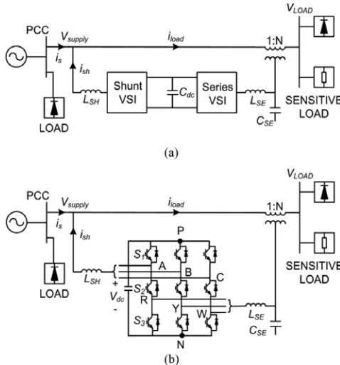
Fig. 1.Representations of (a) back-to-back and (b) nine-switch powerconditioners.
back-to-ISSN 2348 – 7968
638
back configuration to reduce its losses, component count,
and complexity would still be favored, if there is no or
only slight expected tradeoff in performance.
2.
PROPOSED FUZZY BASED NINE SWITCH
POWER CONDITIONER
2.1 Introduction
Fuzzy based nine switch converter operating principles and their existing constrains, describes proposed fuzzy based nine switch power conditioner, control strategies i.e., space vector modulation scheme for generating gating signals, series control and shunt control blocks for compensation problems.
2.2 The nine switch converter operating principles and
existing constrains
The proposed converter has three legs with three switches per leg. The noveltyof this converter is that the middle switch in each of the converter legs is shared bythe rectifier and inverter, thereby reducing the switch count by 33% in comparison tothe back-to-back converter. The utility power is delivered to the load partially throughthe middle switches (direct AC/AC conversion) and partially through a quasi DC linkcircuit. Fig. 1(b) representation shows the nine switch power conditioner. The nine switch converter is formed by tying three semiconductor switches perphase, giving a total of nine for all three phases. The nine switches are powered by acommon dc link, which can either be a micro source or a capacitor depending on thesystem requirements under consideration. Like most reduced component topologies,The nine switch converterisformed bytyingthreesemiconductor switchesperphase,givingatotalofnineforallthreephases. The nine switches are powered by a common dc link, which can either be a micro source or a capacitor depending on the system requirements under consideration.
! ON, if upper reference is larger than carrier
OFF, otherwise
! ON, if lower reference is smaller than carrierOFF, otherwise
S2= S’1 S’3 ... (1)
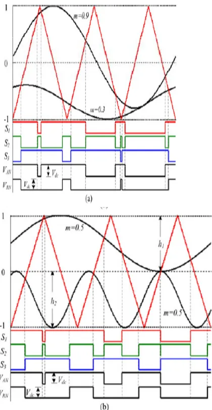
Where is logical XOR operator.Signals obtained from equation 1, when applied to the nine-switch converter, and then lead to those output voltage transitional diagramsdrawn in Fig.2.1 for representing and per phase. Together, these voltage transitions show that the forbidden state of = 0V and
is effectively blocked off.
Fig. 2.1.Arrangementsof
referencehaving(a)thesamefrequencybutdifferentamplitudes, and(b) different frequencies butthesameamplitude.
Table 1 Switch states and output voltages per phase
ON ON OFF
ON OFF ON
0
OFF ON ON 0
0
ISSN 2348 – 7968
639
maximum modulation ratio of 0.5 each, extendible by 1.15 timesif triplen offsetis added, in order to avoid crossover. The limited phase-shift constraint, associatedwith references of the same frequency and combined modulation ratio of greater than1.15 with triplen offset added (=1.2 as an example), has recently beenshown to adapt well with online uninterruptible power supplies, which indeed is aneat and intelligent application of the nine-switch converter. This, however, is only asingle application, which by itself is not enough to bring forward the full potential ofthe nine switch converter.
Fig.2.2 Transitions Of Modulating References And Control Schemes Between Normal (Left) And Sag Mitigation (Right) Modes.
3.
SIMULATION RESULTS AND ANALYSIS
3.1 Introduction
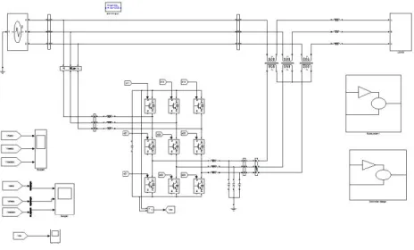
The development of MATLAB/SIMULINK simulation model of fuzzy based nine switch Power conditioner and its space vector selectionusing MATLAB/SIMULINK for harmonic reduction and power factor improvement. Italsodiscusses the simulation procedure for implementing the Simulink model of proposed system.
The simulation results of simulation models ofnine switch power conditioner, followed by with basic shunt active filtercompensation and series active filter compensation for harmonic reduction and powerquality improvement. Then the Total Harmonic Distortion (THD) analyses for theproposed nine switch power conditioner with compensation and withoutcompensation are compared.In the given model the source voltage is selected as 230V rms value. Thus theline is maintained at 230V automatically through the transformers. From the load endside tapping is taken to the three phase transformers and the output of the three phasetransformer is given to the universal bridge. The capacitors which are connected inseries are storing the D.C. value of voltage and these are feeding to the universalbridge 2 which is converting the D.C.to A.C. voltage.The required voltage for the line under the fault to compensate the voltage sagis determined by the pulses. Then the universal bridge draws required voltage toconvert it intoalternative voltage and it feeds to the filters. The inductive filters andcapacitive filters are filtered the harmonics and provide the alternating voltage to theline through the transformers. Here the fault is created and the fault block isconnected. The fault which is selected is three phase fault.
Fig. 3.1 Simulink Model of Fuzzy based Nine Switch Power Conditioner
Table. 3.1 The Applied Values in the Simulation of Proposed System
Fig. 3.2Space Vector Selection
Parameter Value
Input voltage Frequency DC link capacitor DC link voltage Shunt filter inductance Series filter inductance Series filter capacitance Load resistance Load inductance
230V 50Hz 33Mf 270V 5mH 0.5mH 30µF 100Ω
ISSN 2348 – 7968
640
Fig. 3.3 Reference Signal GenerationFig. 3.2 shows the space vector selection for generating gating signals. Fig. 3.3shows the reference signals generation with standard mathematical computation. Togenerate time varying, 60 Hz sinusoidal signal with estimated phase angle, theMATLAB function blocks are used. The sine and cosine signals, at unity magnitude,from the Phase Locked Loop (PLL) are used to maintain the synchronization betweenthe generated reference signal and the supply voltage.This signal multiplied with computed series voltage magnitude gives therequired series-injected voltage signal with desired phase angle shift. Similarly, withphase angle difference the reference signals for other two phases are generated. Thesethree reference series-injected voltages are compared with sensed three-phase seriesinjected voltages and the errors are then processed by hysteresis controller to generatethe required switching signals for series inverter switches.
3.2 RESULTS OF NINE SWITCH POWER
CONDITIONER DURING NORMAL CONDITION
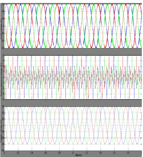
The performance of the proposed integrated nine switch power conditioner isevaluated with a detailed simulation model using MATLAB/SIMULINK. Fig. 3.4shows the supply voltage, series injection voltage and load voltage with a higher gridTHD, and with both series and shunt compensation activated. The supply voltage isdistorted and appears across the load if series compensation is deactivated and thetransformer is bypassed. The distortion would, however, be largely blocked from propagating to the load, and upon activating the series compensation scheme with theshunt compensation scheme still kept executing. With the injection of series voltagethe source voltage become sinusoidal and having fewer harmonic.
Fig. 3.4 Load, Series Injection, and Supply Voltages during Normal Power Conditioning Mode
Fig. 3.5 shows the load, shunt injection and supply currents conditioned by thenine switches UPQC to verify its shunt compensating capability. The load current isheavily distorted due to nonlinear diode rectifier load, but the source currentapproached sinusoidal due to the compensation current injected by shuntcompensator.
ISSN 2348 – 7968
641
Table 3 .2 THD Analysis
Fig 3.6: Total Harmonic Distortion of Source current shows 3.92% with PI controlled converter
Fig 3.7: Total Harmonic Distortion of Source current shows 1.86% with Fuzzy controlled converter.
3.3 RESULTS OF FUZZY BASED NINE SWITCH
CONVERTERPOWER CONDITIONER DURING
NORMAL TO SAGCONDITION
A programmable source is used to introduce sag. Fig. 3.7 shows thecompensated load voltage, series injection voltage, sagged grid voltage during normalto sag condition. The grid voltage is sinusoidal throughout the whole transitionalprocess with decrease in amplitude during sag period. This decrease in grid voltage istransferred to the series terminal of the nine switch power conditioner. The decreasein power is associated with low series voltage is forced out to shunt terminal, need tomaintain load voltage unchanged.Fig. 3.8 shows the compensated load current; shunt injection current, gridcurrent during normal to sag condition. The DC link voltage of nine switch powerconditioner is always to maintain higher than the back to back conditioner. The grid current is obviously sinusoidal throughout the whole transitional process with anincrease in amplitude noted during the period of grid sag.
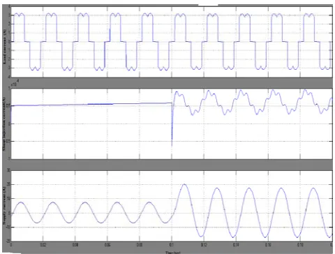
Fig. 3.8 Load, Series Injection and Supply Current during Normal to Sag Mode
Fig. 3.9 Load, Shunt Injection and Supply Current during Normal to Sag Mode
The increase in grid current is transferred to the shunt terminal of the nineswitch power conditioner, whose absorbed (negative of injected current now has aprominent fundamental component, as also reflected by the second row of waveformsplotted in Fig. 3.8. Upon processed by the nine-switch power stage, the incrementalpower associated with the higher shunt current is eventually forced out of the seriesterminal as an injected voltage, needed for keeping the load voltage and powerunchanged. Fig.3.9 shows the conditioner DC link voltage regulated at 270Vthroughout the whole sag transition.
ISSN 2348 – 7968
642
4.CONCLUSION AND FUTURE SCOPE
4.1 Conclusion
The Fuzzy based nine switch converter is simulated using MATLAB/SIMULINK. It effectively reduces the current and voltage harmonics. The nineswitchconverter is more suitable for replacing back- to-back converter in “series–shunt” systems. As a further performance booster, a modified space vectormodulation and 120 degree modulation scheme is presented for reducing the overallcommutation count by 33%. It is also compensated for voltage sags, total harmonicdistortion with proper series and shunt controls. Since thenumber ofswitchesrequired is less compared to conventional converter, the switching losses are less.
4.2 FUTURE SCOPE
The proposed system is the model which comes under the category of thebasic converter in FACTS. It is the basic converter for all the upcoming FACTSdevices like UPQC etc. The converter used here is nine switch converter i.e., ac-acconverter. Recent works done on this nine switch converter are up-grading. So we canadopt this technology to any FACTS devices which need the AC-DC-AC conversion.
It can be used for STATCOM and SVC for reduce power compensation with less switching losses.
It can be used in industrial drives for supplying high quality power with less switching devices.
So, the proposed technology can act as the basic model for the upcomingtechnologies in FACTS and the control strategy can be implemented to many closedloop systems.
REFERENCES:
[1] Edward. F. Fuchs, Mohammad. A. S. Masoum, “Power Quality in Power Systems and Electrical Machines”, ISBN-970-0-12-369536, Elsevier Inc., 2008.
[2] Alexander kusko and Marc.T.Thompson, “Power Quality in Electrical Systems”, The McGraw-Hill Company, Inc. 2007.
[3] B.Han,B.Bae,H.Kim,andS.Baek, “Combined
operationofunifiedpower-qualityconditionerwithdistributedgeneration,”IEEETrans.P ower Delivery,vol. 21,no.1,pp.330–338,Jan.2006. [4] KhadkikarandA.Chandra,“Anewcontrol
philosophyforaunifiedpowerqualityconditioner(UPQC)toc oordinateload-reactivepowerdemandbetween
shuntandseriesinverters,” IEEETrans. PowerDel., vol. 23,no.4,pp.2522–2534,Oct.2008.
[5] Y.,W.Li,D.M.Vilathgamuwa,andP.C.Loh,“Agrid-
interfacingpowerqualitycompensatorforthree-phasethree-wiremicro gridapplications,” IEEE Trans.PowerElectron.,vol.21,no.4,pp.1021–1031,Jul. 2006.
[6] P.C.Loh,F.Blaabjerg, F.Gao,A.Baby,andD.A.C.Tan,“Pulse
width modulationofneutral-point-clamped indirectmatrixconverter,” IEEETrans. Ind.Applicant.,
vol.44,no.6,pp.1805–1814,Nov./Dec.2008.
[7] E.Ledezma,B.McGrath,A.Munoz,andT.A.Lipo,
“Dualac-drive systemwithareducedswitchcount,”IEEE Trans.Ind.Applicat.,vol.37,no. 5,pp.1325–
1333,Sep./Oct.2001.
[8] M.Jones, S.N.Vukosavic,D.Dujic,
E.Levi,andP.Wright,“Five-leg
inverterPWMtechniqueforreduced switchcounttwo-motorconstant powerapplications,” IETProc.Electric PowerApplicat.,vol.2,no.5,pp. 275–287,Sep.2008.
[9] C.Liu,B.Wu,N.R.Zargari,D.Xu,andJ.Wang,“Anovelthree-phasethree-legac/acconverterusingnineIGBTs,”
IEEETrans.Power Electron., vol.24,no.5,pp.1151–1160, May2009.
P.A.Chandrakanth Reddy, currently pursuing M.Tech with
POWER &INDUSTRIAL DRIVES as specialization in AVR & SVR College of Engineering and technology, Nannur, Kurnool, Andhra Pradesh ,India. Had Obtained B.Tech degree from Gates Institute of Technology, Gooty ,Anantapur, Andhra Pradesh, India.
A.PRAVEEN KUMAR received his B.Tech Degree in Electrical and Electronics Engineering JNT University .He then received his M.Tech Power systems from JNTU University. He entered in to teaching field in 2002 as a Lecturer and latter promoted as Assistant Professor Presently he is working as Associate Professor & Head of the Department of EEE in AVR&SVR College of Engineering Technology, Nannur, Kurnool (AP,India).. A.PRAVEEN KUMAR has guided several B.Tech Projects M.Tech dissertations. He is the life member of AMIE. He has also delivered special Lectures in various engineering colleges. He has published 18 research papers in National/International Journal/Conferences
G.SATISH KUMAR received his B.Tech Degree in Electrical and Electronics Engineering JNT University .He then received his M.Tech in Power Electronics from JNTU University. He entered in to teaching field in 2006 as a Lecturer and latter promoted as Assistant Professor Presently he is working as Assistant Professor of the Department of EEE in AVR&SVR College of Engineering and Technology.