ISSN (Print) : 2320 – 3765 ISSN (Online): 2278 – 8875
I
nternational
J
ournal of
A
dvanced
R
esearch in
E
lectrical,
E
lectronics and
I
nstrumentation
E
ngineering
(A High Impact Factor, Monthly, Peer Reviewed Journal)
Website: www.ijareeie.com
Vol. 7, Issue 9, September 2018
Effect on Transient Stability Using PSS &
SVC in the Power System
Savay jain1, Ajit Rajpoot2
Research Scholar, Department of Electrical Engineering, VITM, Gwalior, India1
Assistant Professor, Department of Electrical Engineering, VITM, Gwalior, India2
ABSTRACT: To maintain the stability and steady state operation of power system causing from disturbance or oscillation, faults and suddenly changing of the load, voltage instability, voltage sag, disturbance in frequency, stability is the most important factor regarding to power system. Due to instability, different problems come forward in power system such as fluctuation in voltage and frequency, which may cause damage or failure of power system. The Static Var Compensator (SVC) is also used to improve stability in the system because of its role in reducing the reactive power in the electrical transmission lines. This paper presents an application of (SVC) in electrical transmission lines and PSS in two areas, two generator test power system. Using Matlab software to design and implements control system and study the effect of damping oscillations in stability power system after proposed faults in transmission lines of research model that used (PSS-generic and multiband) types and automatic voltage regulator (AVR).
KEYWORDS: AVR; Power System; PSS; SVC; Short Circuit; Transient Stability.
I. INTRODUCTION
A simple transmission system containing two hydraulic power plants. A static var compensator (SVC) and power system stabilizers (PSS) are used to improve transient stability and power oscillation damping of the system. Various types of FACTS devices consist of Distribution Static Synchronous Compensator (D-STATCOM), Thyristor Controlled Series Compensator (TCSC), Static Series Synchronous Compensator (SSSC), Static VAR Compensator (SVC), Unified Power Flow Controller (UPFC), Thyristor Controlled Series Reactor (TSSR), Thyristor Controlled Voltage Reactor (TCVR), Interline Power Flow Controller (IPFC) and another more devices.
ISSN (Print) : 2320 – 3765 ISSN (Online): 2278 – 8875
I
nternational
J
ournal of
A
dvanced
R
esearch in
E
lectrical,
E
lectronics and
I
nstrumentation
E
ngineering
(A High Impact Factor, Monthly, Peer Reviewed Journal)
Website: www.ijareeie.com
Vol. 7, Issue 9, September 2018
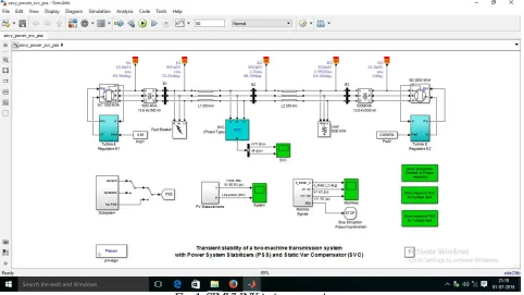
Fig. 1. SIMULINK test power system.
II. SYSTEM DESCRIPTION
The above Figure represents a system whose characteristics are: (a) Two synchronous generators.
(b)Two power transformers of 13.8 kV / 500 kV. (c)Three busbars.
(d) A transmission line of 500 kV and 700 km.
(e) Two PSS and two AVR (Automatic Voltage Regulator). (f) The SVC characteristics: 200 Mvar.
(g) A purely resistive load of 5000 MW confirm that you have the correct template for your paper size.
Note that the load center is modeled by (5000 MW) resistive load which is fed by the remote of (1000 MVA-plant M1), and a local generation of (5000 MVA-plant M2). A load flow has been performed on this system for M1 and M2 with generating rate of (950 MW and 4046 MW) respectively while the line carries (944 MW) which is closed to its surge impedance loading (SIL = 977 MW). The shunt compensated used in this research is with rate of (200 Mvar) to maintain system stability after faults.
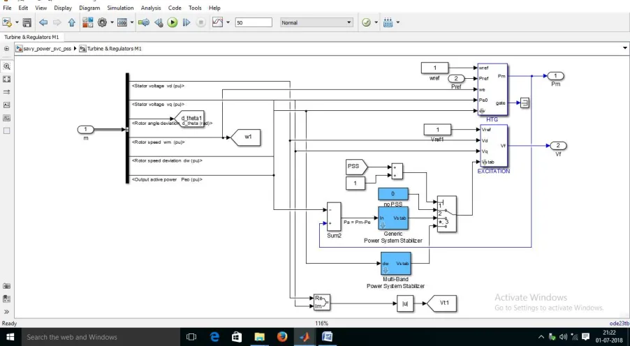
The SVC does not have a power oscillation damping (POD) unit. M1 and M2 are equipped with a Hydraulic Turbine and Governor (HTG), excitation system, and Power System Stabilizer (PSS). Two standard types of stabilizer models can be connected to the excitation system: Generic model using the acceleration power (Pa) which is the difference
between mechanical power (Pm) and electrical output power (Poe) and Multiband model which use a speed deviation
(dw).
III. SIMULATION RESULT AND DESCUSSION
ISSN (Print) : 2320 – 3765 ISSN (Online): 2278 – 8875
I
nternational
J
ournal of
A
dvanced
R
esearch in
E
lectrical,
E
lectronics and
I
nstrumentation
E
ngineering
(A High Impact Factor, Monthly, Peer Reviewed Journal)
Website: www.ijareeie.com
Vol. 7, Issue 9, September 2018
power system stability a single-phase to ground fault and a three-phase fault have been applied on the first section of the line (L1) see in Fig.1.
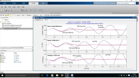
The results have been assembled in the same graph to allow comparison between a various cases (without PSS, with PSS Generic type and with PSS MB type. A. Single-Phase Fault - Impact of PSS - No SVC In this part the SVC is set to operate in fixed susceptance mode with (Bref=0) this is equivalent to putting the SVC out of order. Also a single-phase to ground fault have been applied at t=0.1 s and eliminated at t=0.2 s.
The first trace of Fig. 2 on the Machines scope shows the rotor angle difference d_theta1_2 between the two machines. Power transfer is maximum when this angle reaches 90°. This signal is a good indication of system stability. If d_theta1_2 exceeds 90º for too long a period of time, the machines will lose synchronism and the system goes unstable. The second trace of Fig. 2 shows the speed oscillation of machine M1 Notice that machine 1 speed increases during the fault because during that period its electrical power is lower than its mechanical power.
The third trace of Fig. 2 shows the positive sequence voltage at the SVC bus, we notice that as soon as the fault has been applied the voltage grows to reach 1.08 then this peak is followed by oscillations.
In the blue waveforms we can clearly see that, if there is no PSS than system can’t be able to sustain stability and lose it synchronism (see Fig. 2).
In the red waveforms notice that when we use PSS Generic type system becomes stable but there is low frequency oscillation present (see Fig. 2).
In the magenta waveforms we notice that when we use PSS MB type system may be stable with no low frequency oscillation. So PSS MB type is more accurate compare to PSS genetic type.
ISSN (Print) : 2320 – 3765 ISSN (Online): 2278 – 8875
I
nternational
J
ournal of
A
dvanced
R
esearch in
E
lectrical,
E
lectronics and
I
nstrumentation
E
ngineering
(A High Impact Factor, Monthly, Peer Reviewed Journal)
Website: www.ijareeie.com
Vol. 7, Issue 9, September 2018
Fig. 3. Comparison of simulation result for a 6-cycle, Three phase fault PSS (Generic Pa) in service; No SVC
ISSN (Print) : 2320 – 3765 ISSN (Online): 2278 – 8875
I
nternational
J
ournal of
A
dvanced
R
esearch in
E
lectrical,
E
lectronics and
I
nstrumentation
E
ngineering
(A High Impact Factor, Monthly, Peer Reviewed Journal)
Website: www.ijareeie.com
Vol. 7, Issue 9, September 2018
Fig. 5. Internal block diagram of Turbine & Regulator M1
ISSN (Print) : 2320 – 3765 ISSN (Online): 2278 – 8875
I
nternational
J
ournal of
A
dvanced
R
esearch in
E
lectrical,
E
lectronics and
I
nstrumentation
E
ngineering
(A High Impact Factor, Monthly, Peer Reviewed Journal)
Website: www.ijareeie.com
Vol. 7, Issue 9, September 2018
Fig. 7.Run Time simulation result V. Pos sequence B1,B2,B3 (pu) & Line power
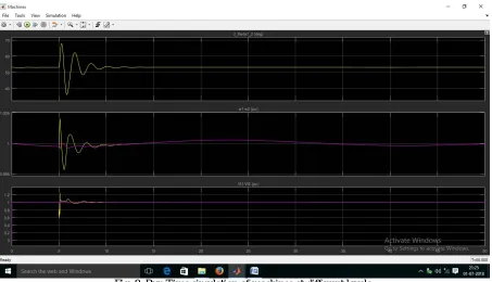
Fig. 8. Run Time simulation of machines at different levels.
ISSN (Print) : 2320 – 3765 ISSN (Online): 2278 – 8875
I
nternational
J
ournal of
A
dvanced
R
esearch in
E
lectrical,
E
lectronics and
I
nstrumentation
E
ngineering
(A High Impact Factor, Monthly, Peer Reviewed Journal)
Website: www.ijareeie.com
Vol. 7, Issue 9, September 2018
however the two PSS has been maintained in service by fixing value=1 in the PSS constant block. Also a three-phase to ground fault have been applied at t=0.1 s and eliminated at t=0.2 s. The results have been assembled in the same graph to allow comparison between the two tests (without SVC, with SVC).Here we show that if there is three phase transient fault than Without SVC both PSS not able to maintain the stability. By looking at the red waveforms we should observe that the two machines quickly fall out of synchronism after fault clearing. In order not to pursue unnecessary simulation, the Simulink 'Stop' block is used to stop the simulation when the angle difference reaches 3*360degrees.Now the SVC is set to operate in voltage regulation mode. The SVC will now try to support the voltage by injecting reactive power on the line when the voltage is lower than the reference voltage (1.009 pu).In steady state the SVC will therefore be 'floating' and waiting for voltage compensation when voltage departs from its reference set point.
The results of these studies show that the SVC has an excellent capability in damping power system oscillations and enhances greatly the dynamic stability of the power system. We also note that the stabilization time is minimal.
IV. CONCLUSION
The work described in this paper illustrates modeling of a simple transmission system containing two hydraulic power plants. A static Var compensator (SVC) and power system stabilizers (PSS - generic & multiband types) are used to improve transient stability and power oscillation damping of the system. The results depict that a system has been developed successfully for the stability of transients in a bi-machine transmission system with PSS and SVC. The basic structure of (PSS) is operating under typical control generator while the basic structure of (SVC) is operating under typical bus voltage control. The proposed controller is used (PSS) & (SVC) under abnormal system conditions.
From simulation results of proposed model we can conclude:
(a) The proposed model is oscillatory and instable with absence effects of (PSS) and (SVC).
(b) The selective of (PSS) are capable of proving sufficient damping to the steady state oscillation and transient stability voltages performance over a wide range of operating conditions and various types of disturbances of the system used in proposed model.
(c) If there is Single line to ground fault than the PSS able to sustain the stability, but using SVC the angle deviation is reduce.
(d) If there is three phase transient fault than Without SVC both PSS not able to maintain the stability.
(e) Compare working two types of (PSS), the multiband type oscillation is quickly damped that which in generic type.
REFERENCES
[1] M.H. Zakaria, “Optimisation des paramètres d’un FACTS shunt pour l’amélioration de la stabilité transitoire d’un système électrique,” SETIF University of Technology, Juin, 2012.
[2] N.G. Hingorani and L. Gyugyi, “Understanding FACTS: concepts and technology of flexible AC transmission systems,” IEEE Press, New York, 2000.
[3] R. Haimour, “Controle des Puissances Réactives et des Tensions par les Dispositifs FACTS dans un Réseau Electrique,” Ecole Normal Supérieurde l’Enseignement Technologique d’Oran, 2009.
[4] S. Panda and N.P. Padhy, “Power System with PSS and FACTS Controller Modeling, Simulation and Simultaneous Employing Genetic Algorithm,” International Journal of Electrical and Electronics Engineering, pp.9-18, 2007.
[5] K. Salma, B. Wissem and K. Mohamed Ben Ali, “Improvement of power system stability by static Var compensator and tuning employing genetic algorithm,” International Journal of Modern Nonlinear Theory and Application, pp.113-123, 2014.
[6] T. R. Hussein, “Using Power System Stabilizers (PSS) And Shunt Static Var Compensator (SVC) For Damping Oscillations In Electrical Power System,” Journal of faculty MAAMOUN.
[7] A. Ali. “Development of system with transitory steadiness of a bimachine transmission system with power system stabilizers and static Var compensator,” International Journal of Engineering Research and Applications, vol. 3, Issue 3, pp.1121-1125, May-Jun 2013.
[8] K. Alok and D. Surya Bhushan, “Enhancement of transient stability in transmission line using SVC facts controller,” International Journal of Recent Technology and Engineering, Vol. 2, Issue 2, May 2013.
[9] M. Mohammad , “Voltage stability analysis with static Var compensator (SVC) for various faults in power system with and without power system stabilizers (PSS),” Research Journal of Applied Sciences, Engineering and Technology, vol. 3, No. 7, pp.668-676, 2011.
[10] B. Omar Mohammed, “Analyse de la stabilité transitoire dans un réseau électrique comportant un PSS et un SVC,” Mémoire de magister Département d’électrotechnique, Faculté des sciences de l’ingénieur, Algerie, Sidi Bel abbes, janvier 2014.