for applications such as open-cast mining operations and highly dynamic vehicles such as spaceplanes. Moreover, using GLONASS satellites in addition to GPS is useful for long baseline applications since it increases the numbers of satellites in common view. Japan’s National Aerospace Laboratory (NAL) has been conducting feasibility studies using combined GPS/GLONASS positioning for spaceplane landing systems and the precise navigation of stratospheric airships. This paper presents the results of the first Japanese kinematic GPS/GLONASS flight test. In the test, the difference in estimated position between dual frequency GPS and single frequency GPS/GLONASS systems was found to be within a few centimeters, indicating that GLONASS carrier phase ambiguities were correctly resolved. To demonstrate the benefits of combining GLONASS with GPS navigation, an on-the-fly (OTF) test of instantaneous ambiguity resolution with a 30 degree cutoff angle was performed. The OTF performance of the combined GPS/GLONASS system was found to be similar to that of a GPS system with a cutoff angle of 10 degrees, showing that augmentation of GPS with GLONASS will be useful for highly dynamic vehicle applications.
1.
Introduction
Inertial navigation and Global Positioning System (GPS) satellite navigation have been playing an important role in aircraft en-route navigation and precision landing systems. However, the use of inertial navigation with GPS alone can-not satisfy navigation availability requirements for highly dynamic vehicles such as spaceplanes. Japan has been de-veloping an unmanned space shuttle named HOPE-X (H-II Orbiting Plane eXperimental), and differential GPS (DGPS) integrated with inertial navigation is the main candidate for providing precise navigation data for the vehicle’s automatic landing system. However, the use of GLONASS is desir-able in order to improve the availability and integrity of the navigation system.
In addition to navigation, kinematic Global Satellite Navi-gation System (GNSS) positioning combining GPS and GLONASS is useful for scientific missions such as airborne remote sensing in mountainous areas. In particular, global environment observation from stratospheric airships flying at an altitude of 20 km would yield much useful informa-tion for earth sciences. The stratospheric airship is currently one of Japan’s biggest aerospace projects, and its main uses are earth observation, telecommunications and broadcasting. In this application, since the distance of the aircraft from ground reference sites may exceed a few hundred kilometers, augmentation of GPS navigation with GLONASS would be beneficial since it would increase the number of satellites in common view.
Copy right cThe Society of Geomagnetism and Earth, Planetary and Space Sciences (SGEPSS); The Seismological Society of Japan; The Volcanological Society of Japan; The Geodetic Society of Japan; The Japanese Society for Planetary Sciences.
Although the results of static or stop-and-go on-the-fly (OTF) satellite navigation performance have been reported by Pratt et al. (1997), Kozlov and Tkachenko (1998), and Habrich (1998), there are few research publications on kine-matic OTF, especially airborne kinekine-matic OTF, since it is not easy to evaluate accuracy on a moving platform. This paper presents the results of kinematic GPS/GLONASS flight test evaluations conducted by Japan’s National Aerospace Labo-ratory (NAL). NAL has been developing its own Kinematic GPS Software (KINGS, Tsujii et al., 1997), and this was modified to process GLONASS data. The performance of this software was then evaluated using flight test data. The main objectives of the evaluation were:
1) Evaluation of the accuracy of L1 single frequency kine-matic GPS/GLONASS positioning against GPS L1/L2 dual frequency profile.
2) Performance evaluation of instantaneous GPS/ GLONASS ambiguity resolution on-the-fly, using the LAMBDA method.
For the evaluation, an Ashtech GG-24 L1 receiver and a Trimble 4000SSI L1/L2 receiver were installed in a re-search aircraft as well as at a ground reference site. The antennae on board the aircraft were installed at separate lo-cations, and attitude information from a carrier DGPS/INS (CDGPS/INS) navigation system was used to correct for this. The CDGPS/INS is an original robust high precision navi-gation system developed by NAL for aircraft CAT-III and spaceplane automatic landing applications (Harigae et al., 1998).
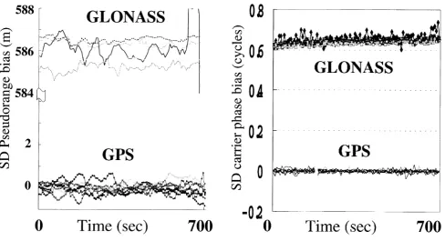
Fig. 1. Single differenced pseudorange bias (meters) of aircraft on-board GG-24 receiver.
In the OTF performance evaluation, cutoff angles of 10, 20, and 30 degrees were used in order to simulate the views of the satellite constellations from the bottom of an open-cast mine or from a manoeuvring aerospace vehicle.
2.
GLONASS Inter-Channel Hardware Biases
The measurement of GLONASS pseudorange contains a frequency-dependent inter-channel hardware bias, as pointed out by Rossbach and Hein (1996), and Kozlov and Tkachenko (1998). A zero-baseline test was therefore conducted in or-der to estimate inter-channel bias and random error, and the resulting data values were used as weights for least-squares adjustment.Figure 1 shows the GPS/GLONASS single differenced pseudorange error of the aircraft on-board GG-24 receiver. It can be seen that there is a large constant bias of approximately 586 meters and inter-channel biases on the order of a few meters. The constant bias appears to be due to the use of an old version of the receiverfirmware, which was not updated prior to the experiments.
Figure 2 shows the single differenced carrier phase in cycles. Although the GLONASS common biases are seen to increase gradually, which might be due to temperature changes, there seem to be no noticeable inter-channel biases. It can therefore be concluded that the GLONASS ambigu-ities would befixed as integers if double differences were taken.
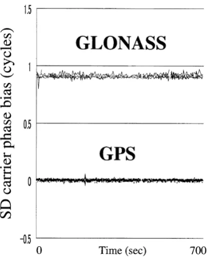
Figures 3 and 4 show respectively the pseudorange and carrier phase biases of the ground-based reference receiver, thefirmware of which had been updated to the latest version at the time of the experiment. It is clear that the inter-channel bias of the GLONASS pseudorange and the random error of the GPS pseudorange are smaller than those of the aircraft
Fig. 2. Single differenced carrier phase bias (cycles) of aircraft on-board GG-24 receiver.
on-board receiver; moreover, there is no apparent trend in the common bias of GLONASS carrier phase.
3.
Positioning Method
The observation equations of the double differenced GPS/GLONASS carrier phase for a short baseline are shown below, where the notation for satellitesiand jis applicable to both GPS and GLONASS (Prattet al., 1997).
ϕi j =ρ
ϕi j: double differenced carrier phase for satellitei and j
(cycles)
ρi: single difference of range to satellitei(meters)
λi: wave length for satellitei(meters)
b: single difference of receiver clock bias (meters)
Ni j: double differenced integer ambiguities (cycles)
εi j: double differenced measurement noise (cycles)
Tropospheric and ionospheric delays are omitted from the above equation as they are negligible in short baseline appli-cations.
The transformation parameters between the GPS84 and PZ90 geoids were derived from Rossbachet al.(1996), and the parameters to adjust for the difference between GPS and GLONASS time were taken from the broadcast navigation messages. The errors in these parameters are not significant for short baselines.
Fig. 3. Single differenced pseudorange bias (meters) of ground reference GG-24 receiver.
Fig. 4. Single differenced carrier phase bias (cycles) of ground reference GG-24 receiver.
For the GPS-GPS double difference, the term relating tob
in Eq. (1) vanishes because the wavelength of the GPS sig-nal is identical for all satellites. Although this term remains in the GLONASS-GLONASS double difference, it can be eliminated by using the pseudorange-based estimate of the clock bias term. After this clock bias term is eliminated, the forms of the GLONASS-GLONASS and GPS-GPS double
Fig. 6. Height of the aircraft vs. time.
Fig. 7. Separation between aircraft and reference receiver.
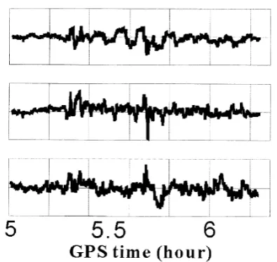
Fig. 9. Position difference (meters) between L1-KGPS and L1/L2 KGPS.
differences become identical and they are then treated in the same way.
Next to the pseudorange-based position estimation, the float solutions of ambiguities are calculated. Position, GPS ambiguities, and GLONASS ambiguities are estimated at the same time using the DD of the GPS pseudorange/carrier and the GLONASS carrier. The GLONASS pseudorange is not used as the inter-channel hardware bias degrades the accu-racy of the estimate. The GPS and GLONASS integer am-biguities are estimated instantaneously using the LAMBDA method proposed by Teunissen (1993) and De Jongeet al.
(1996), and validated by the simple ratio test. The more sophisticated validation algorithms proposed by Rizos and Han (1995) will be implemented in the next version of the software. The performance of the instantaneous ambiguity resolution inflight tests is reported later in this paper.
4.
Flight Test and Results
A flight test was conducted around the Taiki airfield, Hokkaido in the north of Japan in November 1998 using NAL’s Dornier Do.228 research aircraft. An Ashtech GG-24 GPS/GLONASS single frequency receiver was installed in the aircraft, and another GG-24 receiver was located at a surveyed ground reference point. In addition, Trimble 4000 SSI dual frequency receivers were used to obtain the ref-erence flight trajectories. The antennae for the GPS and GPS/GLONASS receivers were installed at different loca-tions in the aircraft, and attitude information from an on-board CDGPS/INS navigation system was used to correct for this. The separation of the antennae was 5.43 meters, and the attitude accuracy of the CDGPS/INS system is bet-ter than 0.1 degrees (3 sigma), so the attitude-derived po-sition propagation error from the GPS L1/L2 antenna to the GPS/GLONASS antenna was less than one centimeter. How-ever, any clock difference between the two receivers may cause a far greater difference in computed position. Al-though the clocks of the two receivers are both designed to synchronize with GPS time to within 1 millisecond, the clock difference between the two receivers may be up to 2 milliseconds. Assuming an aircraft speed of 100 m/s, the
Fig. 10. Position difference (meters) between L1-KGNSS and L1/L2 KGPS.
maximum difference in computed position due to clock skew is therefore 20 cm.
Height profiles from the flight test are shown in Figs. 5 and 6. The horizontal axis of Fig. 5 is along the centerline of Taiki’s runway. Several touch-and-go landings were made during thisflight, as can be seen from thefigures, and the total flight duration was approximately 1.2 hours. Figure 7 shows the separation between the aircraft and the ground reference station, which did not exceed 7 km. Figure 8 shows the number of observed GPS and GLONASS satellites.
The results shown in Fig. 9 are of the comparison between L1-KGPS and L1/L2-KGPS, and in Fig. 10 of the compar-ison between L1-KGNSS and L1/L2-KGPS. The position differences are on the order of a few centimeters RMS, and it is clear that L1-KGPS and L1-KGNSS have approximately the same accuracy. Although some trends can be observed in thefigures, these are due to the clock difference between the two receivers on board rather than ionospheric delay error, which is negligible for such a short baseline.
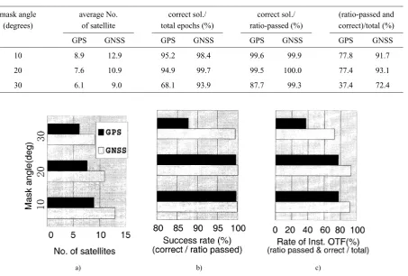
An OTF test was performed to demonstrate the advan-tage of combining GLONASS with GPS navigation. Var-ious mask angles were used to simulate satellite visibility from the bottom of an open-cast mine or from a maneuver-ing aerospace vehicle. The performance of instantaneous ambiguity resolution OTF by the LAMBDA method at mask angles of 10, 20, and 30 degrees is summarized in Table 1. The correct ambiguities were determined using static data taken at the airfield, and maintained during the flight. A threshold value of 2 was used for the ratio test. In gen-eral, the performance of the GNSS is superior to that of GPS alone. When the data are visualized as in Fig. 11, it can be seen that the performance of the GNSS with a mask angle of 30 degrees is similar to that of GPS with a mask angle of 10 degrees.
5.
Conclusions
follow-a) b) c)
Fig. 11. a) Number of observed satellites for various mask angles. b) Success rate of ambiguity resolution on-the-fly (correct solutions/solutions which passed the ratio test). c) Success rate of instantaneous ambiguity resolution on-the-fly (correct and ratio-passed solutions/total epochs).
ing conclusions can be drawn from the results of the test:
1. The positioning accuracy of kinematic GPS/GLONASS is similar to that of kinematic GPS.
2. The instantaneous OTF performance of GPS/ GLONASS with a mask angle of 30 degrees is simi-lar to that of GPS with a mask angle of 10 degrees.
The second conclusion has important implications not only for highly dynamic aerospace vehicles but also for high-altitude or long-range kinematic applications, since using GPS and GLONASS increases the number of satellites in common view.
NAL’s kinematic software will be updated to implement more sophisticated OTF and validation algorithms than were used for this experiment. The software will be applied to the precise positioning of the Japanese stratospheric airship system for earth environmental observation.
Acknowledgments. The authors would like to thank Professor Teunissen for providing useful information about the LAMBDA method. Gratitude is also expressed to the staff of Taiki town office for their kind support during the experiment.
References
Habrich, H., Experiences of the BKG in processing of GLONASS and com-bined GLONASS/GPS observations,Proc. IGS Analysis Center
Work-shop, Darmstadt, February 9–11, 1998.
Harigae, M., T. Tsujii, T. Ono, and T. Inagaki, Flight Evaluations of Carrier DGPS/INS Hybrid Navigation for Automatic Landing,Proc. of ION GPS-98, Nashville, Sept. 15–18, 437–448, 1998.
De Jonge, P. J., C. C. J. M. Tiberius, and P. J. G. Teunissen, Computational Aspect of the LAMBDA Method for GPS Ambiguity Resolution,Proc. of ION GPS-96, 935–944, 1996.
Kozlov, D. and M. Tkachenko, Centimeter-Level, Real-Time Kinemtic Po-sitioning with GPS+GLONASS C/A Receivers,Navigation,45(2), 137– 147, 1998.
Pratt, M., B. Burke, and P. Mirsa, Single-Epoch Integer Ambiguity Reso-lution with GPS-GLONASS L1 data,Proc. ION 53rd Annual Meeting, The Institute of Navigation, 691–699, 1997.
Rizos, C. and S. Han, A New Method of Constructing Multi-Satellite Am-biguity Combinations for Improved AmAm-biguity Resolution,Proc. of ION GPS-95, 1145–1153, 1995.
Rossbach, U. and G. Hein, Treatment of Integer Ambiguities in DGPS/DGLONASS Double Difference Carrier Phase Solution,Proc. of ION GPS-96, 909–916, 1996.
Rossbach, U., H. Habrich, and N. Zarraoa, Transformation Parameters Be-tween PZ-90 and WGS-84,Proc. of ION GPS-96, 279–285, 1996. Teunissen, P. J. G., Least-squares estimation of the integer GPS ambiguities,
Delft Geodetic Computing Centre LGR-series No. 6, 1993.
Tsujii, T., M. Harigae, and M. Murata, The development of Kinematic GPS Software, KINGS, and its application to observations of the crustal movements,J. Geod. Soc. Japan,43(2), 91–105, 1997 (in Japanese). Wang, J., Mathematical Models for Combined GPS and GLONASS
Posi-tioning,Proc. of ION GPS-98, 1333–1344, 1998.