Article
1
Novel S-bend resonator based on a multi-mode
2
waveguide with mode discrimination for a refractive
3
index sensor
4
Do-Hyun Kim 1, Su-Jin Jeon 1, Jae-Sang Lee 1, Seok-Ho Hong 1 and Young-Wan Choi 1,*
5
1 Department of Electrical and Electronics Engineering, Chung-Ang University, 221 Heuksuk-Dong,
6
Dongjak-ku, Seoul, 156-756, Korea; [email protected] (D.-H.K); [email protected] (S.-J.J);
7
[email protected] (J.-S.L); [email protected] (S.-H.H)
8
* Correspondence: [email protected]; Tel.: +82-2-822-5326
9
10
Abstract: In this paper, a multi-mode waveguide-based optical resonator is proposed for an
11
integrated optical refractive index sensor. Conventional optical resonators have been studied for
12
single-mode waveguide-based resonators to enhance the performance, but mass production is
13
limited owing to the high fabrication costs of nano-scale structures. To overcome this problem, we
14
designed an S-bend resonator based on a micro-scale mode waveguide. In general,
multi-15
mode waveguides cannot be utilized as optical resonators, because of a performance degradation
16
resulting from modal dispersion and an output transmission with multi-peaks. Therefore, we
17
exploited the mode discrimination phenomenon using the bending loss, and the resulting S-bend
18
resonator yielded an output transmission without multi-peaks. This phenomenon is utilized to
19
remove higher-order modes efficiently using the difference in the effective refractive index between
20
the higher-order and fundamental modes. As a result, the resonator achieved a Q-factor and
21
sensitivity of 2.3×10³ and 52 nm/RIU, respectively, using the variational finite-difference
time-22
domain method. These results show that the multi-mode waveguide-based S-bend resonator with
23
a wide line width can be utilized as a refractive index sensor.
24
Keywords: mode discrimination; multi-mode waveguide; S-bend resonator; refractive index sensor;
25
integrated optical sensor
26
27
1. Introduction
28
Recently, integrated optical devices for refractive index (RI) sensors have been widely studied
29
for applications such as bio-chemical analysis and temperature monitoring. Structures such as ring
30
resonators, microdisk resonators, Mach–Zehnder interferometers, and Fabry–Perot interferometers
31
have been developed for use as refractive index sensors [1-6]. These are based on measurements of
32
the resonance wavelength peak shift through external refractive index changes when a reaction
33
occurs in the sensing region, such as a bio-chemical reaction of the target or a temperature change.
34
Among optical devices, ring resonators such as liquid core optical ring resonators, split ring
35
resonators, and planar ring resonators have been studied in biological and chemical sensing, because
36
these have considerably high Q-factors and steep slopes [7-10]. Single-mode waveguides have
37
generally been utilized in ring resonators, as they have the advantages of a low propagation loss,
38
small size, and low modal dispersion [11,12]. However, a relatively high-cost fabrication process
39
must be employed, and mass production is difficult as single-mode waveguides typically have
40
widths of several hundred nanometers.
41
To solve this problem, we proposed and designed a novel S-bend ring resonator, based on a
42
multi-mode waveguide exploiting a mode discrimination phenomenon. Mode discrimination means
43
that high-order modes are removed in specific structures, which yield a performance similar to that
44
of a single-mode waveguide by removing the multi-peaks from the multi-mode waveguide. In a
45
multi-mode waveguide, high-order modes have lower propagation constants than fundamental
46
mode, and so the effective refractive index of a high-order mode is smaller than that of a fundamental
47
mode [13,14]. Because the effective refractive index differs between fundamental and higher-order
48
modes, different bending losses are occured on each mode in a bending structure. Therefore, by
49
employing a bending structure yielding a mode discrimination phenomenon based on a multi-mode
50
waveguide, it is possible to solve the problem of the relatively high-cost fabrication process and
51
achieve mass productivity. To exploit this phenomenon, we analyzed and designed an S-bend
52
structure using a multi-mode waveguide to minimize the loss of the fundamental mode and remove
53
higher-order modes. The resonator consisted of the SU-8 2002 polymer, which has a simple
54
fabrication process and good optical transparency [15]. In addition, SU-8 has a smaller refractive
55
index than other materials employed as waveguides, allowing wider line width design of
56
waveguides with the same number of modes. [16]. Furthermore, we designed the multi-mode
57
waveguide-based S-bend resonator without multi-peaks, which yields a similar output transmission
58
to a single-mode waveguide-based resonator for MODE simulation by using the variational
finite-59
difference time-domain (varFDTD) method.
60
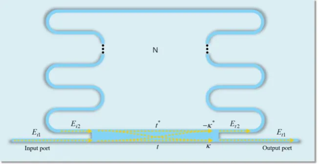
2. DESIGN OF S-BEND RESONATOR
61
The S-bend resonator consists of a ridge waveguide, a multi-mode interferometer (MMI)
62
coupler, and several bend structures, as shown in Figure 1. The waveguide is a highly important
63
component of the resonator design, because the line width of the waveguide determines the range
64
and costs of the available fabrication process. To reduce the fabrication process costs, we designed a
65
multi-mode waveguide with a line width of several micrometers. Furthermore, the coupling
66
efficiency between the optical fiber and the waveguide is higher than a single-mode waveguide,
67
because the multi-mode waveguide has a wider line width. As shown in Figure 2a, the multi-mode
68
waveguide was designed on the SiO2 ( 2 SiO
n = 1.44 at λ = 1.55 μm) substrate. SU-8 2002 polymer (nSU8
69
= 1.564 at λ = 1.55 μm) is utilized as the core material to achieve a simple fabrication process and good
70
optical transparency, and the cross section was designed in a rectangle shape with width (W) of 3 μm
71
and height (H) of 2 μm. In addition, because SU-8 has a smaller refractive index than other materials,
72
a waveguide with the same number of modes can be designed with a wider line width. Figure 2b
73
shows the electric (E) field profiles of eight modes in the designed waveguide.
74
(a) (b)
Figure 2. (a) Cross-section of the ridge waveguide; (b) E-field profiles of SU-8-based waveguide structure.
However, multi-mode waveguides are not generally suitable for use in resonators owing to a
75
performance degradation and a multi-peak output transmission for higher-order modes. To solve
76
this problem, we exploited the mode discrimination phenomenon that can remove higher-order
77
modes. Furthermore, we analyzed and designed a novel S-bend structure based on the multi-mode
78
waveguide to apply the mode discrimination phenomenon, as shown in Figure 3. The simple
79
approximation of the bending loss is given as follows
80
exp( ),
K cR
where (2 eff)3/2eff n c
n
(1)
81
The value of K depends on the refractive index of the core and cladding, and also the thickness
82
of the waveguide, Δneff is the difference between the cladding index and modal effective index neff,
83
and R is the radius of the semi-circle [17]. In equation 1, it can be observed that the bending loss is
84
inversely proportional to the radius and effective refractive index. The effective refractive index of
85
the mode is expressed by equation 2.
86
0
eff n
k
(2)
87
Here, is the propagation constant and k0 is the wavenumber in free space. The effective
88
refractive index also decreases as the order of the mode increases in equation 2, because the
89
propagation constants of high-order modes are smaller than those of the fundamental mode. In other
90
words, the difference in the effective refractive index between the modes leads to different losses in
91
a structure with the mode discrimination phenomenon. Therefore, the multi-mode waveguide can
92
yield a performance similar to that of a single-mode waveguide by removing the higher-order modes.
93
As shown in Figure 3b, we constructed the S-bend structure by cascading the semi-circles shown in
94
Figure 3a.
95
(a) (b)
In general, the bending loss factor in a ring resonator should be reduced [18,19]. However, we
96
focused on the difference in the effective refractive index between the fundamental mode and
higher-97
order modes and analyzed the bending loss according to the radius of the semi-circle for the mode
98
discrimination phenomenon. Higher-order modes with lower effective refractive indexes cause a
99
greater bending loss than does the fundamental mode. Table 1 lists the bending loss (%) for each
100
mode according to the radius of the semi-circle.
101
Table 1. Bending loss of each mode according to the radius.
102
R (𝝁𝒎) TE0 TM0 TE1 TM1 TM2
Bending loss (%)
12.0 0.8 1.0 3.2 2.8 20.8
11.5 1.1 1.7 3.3 3.1 48.3
11.0 1.2 1.8 3.8 3.3 28.6
10.5 1.5 1.6 5.0 5.2 32.7
10.0 2.2 2.0 7.9 7.8 46.8
9.5 3.6 4.0 13.1 14.1 46.2
An important factor in our proposed resonator is that there must be some difference in the
103
bending loss between the fundamental and second modes. This is because if the bending loss
104
difference between the fundamental and second modes is very small, then the mode discrimination
105
phenomenon cannot be efficiently applied as the removal ratio of each mode is similar. Furthermore,
106
because the bending loss increases in proportion to the number of semi-circles, the loss of the
107
fundamental mode should be small, and thus a radius of less than 9.5 μm is not suitable. The bending
108
losses at a radius of 10 μm are 2.0% and 2.2% in transverse magnetic (TM) 0 and transverse electric
109
(TE) 0, and 7.8% and 7.9% in TM1 and TE1, respectively. Each difference is approximately 6%. This
110
represents an optimized condition, with a loss difference from the second mode that minimizes the
111
bending loss in the fundamental mode, which is suitable for applying the mode discrimination
112
phenomenon. The higher-order modes above TM2 are omitted from Table 1, as the bending losses
113
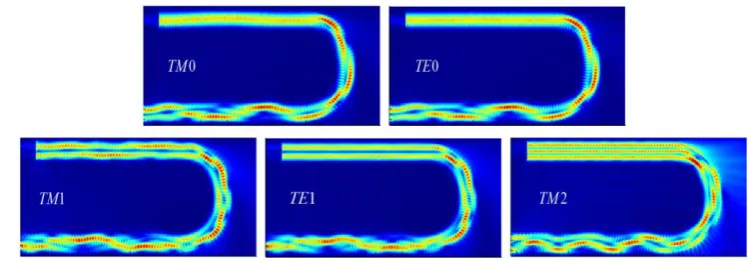
tend to be considerably large. Figure 4 depicts the field profile for each mode at R = 10 μm. This
E-114
field profile can visually confirm that each mode is removed by the mode discrimination
115
phenomenon in the semi-circle structure.
116
Figure 4. E-field profile of each mode in the semi-circle.
The S-bend resonator was designed as shown in Figure 1 by applying the previously defined
117
mode discrimination phenomenon at R = 10 μm. The value of N represents the number of layers, each
118
composed of two semi-circles. The resonator was constructed using a multi-mode interferometer
119
(MMI) coupler rather than a direct coupler with a very sensitive ratio change, owing to the nano-scale
120
coupling gap. In addition, the MMI coupler is wider than the designed waveguide, which can allow
121
cost-effective fabrication. The MMI length was determined as 124 μm, and approximately 3 dB of the
122
input source is coupled into the resonator.
123
We can simply analyze the S-bend resonator using the transfer function of a single-ring
126
resonator. Using this model, the relationship in the MMI coupler can be expressed as
127
1 1
* *
2 2
t i
t i
t
E E
E t E
(3)
128
where t and κ are the transmission and coupling coefficients, respectively. The round trip in the ring
129
is given by
130
2 2
j
i t
E
e E (4)131
Here, α is the attenuation coefficient considering the propagation and bending losses of S-bend
132
resonator, and θ is the phase difference per round trip. Then, the transmitted intensity can be
133
expressed as
134
2 2 2
1 1 2 2
2 cos
1 2 cos
t t
t t
P E
t t
(5)
135
Because the transmitted intensity is affected by the attenuation coefficient, the value of N is
136
critical in designing the resonator. As the value of N increases, mode discrimination can effectively
137
be applied. However, if the value of N becomes too large, then the total loss increases and the
138
performance of the resonator degrades. Therefore, the performance of the resonator according to N
139
is analyzed in Section 3.
140
3. Results and Discussion
141
The performance of the resonator was analyzed by fixing the radius at 10 μm and varying N.
142
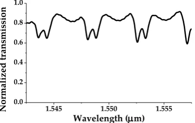
First, N = 1 represents a stadium type resonator structure composed of two semi-circles. The bending
143
losses of the fundamental and second modes are calculated as (2)2 = 4% and (7.8)2 = 60.8%, respectively,
144
using the data in Table 1. This indicates that the mode discrimination phenomenon is not properly
145
applied, as higher-order modes of approximately 39% or over remain. Figure 5 shows that the output
146
spectrum exhibits multiple peaks owing to the higher-order modes, making this difficult to employ
147
as an RI sensor. Therefore, we need to remove the higher-order modes more effectively, and so we
148
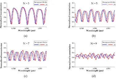
increased N. Owing to the structural characteristics of the S-bend resonator, only an odd number N
149
can be analyzed.Figure 6 depicts the output transmission of the S-bend resonator according to the
150
background index change (1 to 1.01) when N is 3, 5, 7, and 9. The main performance indicators of the
151
spectra shown in Figure 6 are listed in Table 2.
152
153
154
Figure 5. Normalized transmission of S-bend resonator with N = 1.
1.545 1.550 1.555 0.0
0.2 0.4 0.6 0.8 1.0
No
rm
ali
zed
tran
sm
issio
n
The Q-factors for each N are 1.9×10³, 1.9×10³, 2.3×10³, and 2.2×10³ and the sensitivities are 32,
155
39, 52, and 54 nm/RIU, respectively, when converted to the refractive index unit (RIU). As the value
156
of N increases, the higher-order modes are removed more effectively, and so the sensitivity and
Q-157
factor increase. However, the decrease in the extinction ratio (ER) as N increases results from a total
158
power loss in the higher-order modes. When N is greater than 9, the ER is 1.36 dB or less, which is
159
too small for usage as an RI sensor. The free spectral ranges (FSRs) are 3.1, 2.24, 1.87, and 1.51 nm
160
when N is 3, 5, 7, and 9, respectively, and the FSR decreases because the length of the resonator
161
increases with N.
162
Table 2. Detailed performance indexes of the S-bend resonator according to N.
163
N 3 5 7 9
FSR (nm) 3.1 2.24 1.87 1.51
Q-factor 1.9×10³ 1.9×10³ 2.3×10³ 2.2×10³
Sensitivity 32 nm/RIU 39 nm/RIU 52 nm/RIU 54 nm/RIU
Extinction ratio 9.7 dB 4.7 dB 4.3 dB 1.36 dB
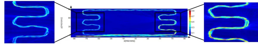
Figure 7 shows the resonance peak shift as the background RI (δn) is varied. As a result of
164
measuring the shifts according to N, when the RI is changed to 0.05 with an interval of 0.01, the
165
sensitivity increases linearly in proportion to N. Figure 8 depicts the E-field profile of the S-bend
166
resonator when N = 5. From the intensities of the E-field on the right and left enlarged profiles, it can
167
be visually observed that the higher-order modes are removed by the bending loss passing through
168
each bend.
169
(a) (b)
(c) (d)
Figure 6. Transmission spectrum according to N when the background index of the S-bend resonator is 1 and
Figure 8. The E-field profile of S-bend resonator with N = 5 at λ = 1.55 μm.
4. Conclusions
170
In this paper, we proposed and designed a novel S-bend resonator for an RI sensor based on a
171
multi-mode waveguide exploiting a mode discrimination phenomenon. Conventional multi-mode
172
waveguides suffer from a performance degradation when designing resonators, owing to modal
173
dispersion. To solve this problem, we designed the S-bend structure to exploit the mode
174
discrimination phenomenon. The S-bend resonator using this structure removes the multi-peaks in
175
the output transmission, and yields a similar performance to a single-mode waveguide. Simulation
176
results show that a Q-factor of 2.3×10³ and sensitivity of 52 nm/RIU can be achieved using the
177
varFDTD method. The sensitivity and Q-factor are slightly lower than those of a single-mode-based
178
ring resonator, but compatible with an RI sensor. Because the S-bend resonator’s line width is greater
179
than those of a single-mode resonator, this can lead to a lower fabrication process cost and higher
180
mass productivity. Thus, the proposed S-bend resonator can be utilized for on-chip refractive index
181
sensors and integrated optical resonator sensors at a competitive price. The mode discrimination
182
phenomenon applied to the S-bend resonator can be utilized in various structures, such as curved
183
structures and total internal reflection mirrors, and will have significant applications in the optical
184
sensor field.
185
186
Author Contributions: Conceptualization, D.-H.K.; methodology, D.-H.K. and Y.-W.C.; software, D.-H.K.;
187
validation, D.-H.K. and S.-J.J.; formal analysis, S.-J.J. and J.-S.L.; investigation, S.-H.H; resources, D.-H.K.; data
188
curation, J.-S.L. and S.-H.H.; writing—original draft preparation, D.-H.K.; writing—review and editing, D.-H.K.
189
and Y.-W.C.; visualization, S.-H.H; supervision, Y.-W.C.; project administration, Y.-W.C.
190
Acknowledgments: This research was supported by the Basic Science Research Program through the National
191
Research Foundation of Korea (NRF) funded by the Ministry of Education (NRF-2018R1D1A1B07048145) and
192
by the Chung-Ang University Research Scholarship Grants in 2018.
193
Conflicts of Interest: The authors declare no conflict of interest.
194
References
195
1. Baehr-Jones, T.; Hochberg, M.; Walker, C. High-Q ring resonators in thin silicon-on-insulator. Appl. Phys.
196
Lett 2004, 85, 3346-3347, doi: https://doi.org/10.1063/1.1781355)
197
Figure 7. Resonance wavelength peak shift according to N.
0.00 0.01 0.02 0.03 0.04 0.05 0
500 1000 1500 2000
2500 Number of bends layer (N)
N = 3 N = 5 N = 7 N = 9
Re
sona
nce pe
ak s
hift
(pm
)
2. Gandolfi, D.; Ramiro-Manzano, F.; Rebollo, F, J, A.; Ghulinyan, M.; Pucker, G.; Pavesi, L. Role of Edge
198
Inclination in an Optical Microdisk Resonator for Label-Free Sensing. sensors 2015, 15, 4796-4809,
199
doi: https://doi.org/10.3390/s150304796
200
3. Kim, H, S.; Park, J, M.; Ryu, J, H.; Kim, S, B.; Kim, C, M.; Choi, Y, W.; Oh, K, R. Optical biochemical sensor
201
based on half-circled microdisk laser diode. Opt Express 2017, 25, 24939-24945,
202
doi: https://doi.org/10.1364/OE.25.024939
203
4. Lee, T,K.; Oh, G,Y.; Kim, H, S.; Kim, D,G.; Choi, Y,W. A high-Q biochemical sensor using a total internal
204
reflection mirror-based triangular resonator with an asymmetric Mach–Zehnder interferometer. Opt
205
Commun 2012, 285, 1807-1813, doi: https://doi.org/10.1016/j.optcom.2011.11.089
206
5. Zhang, Y.; Zou, J.; Cao, Z.; He, J. J. Temperature-insensitive waveguide sensor using a ring cascaded with
207
a Mach–Zehnder interferometer Opt. Lett 2019, 44, 299-302, doi: https://doi.org/10.1364/OL.44.000299
208
6. Wei, T.; Han, Y.; Li, Y.; Tsai, H, L.; Xiao, Hai. Temperature-insensitive miniaturized fiber inline Fabry-Perot
209
interferometer for highly sensitive refractive index measurement. Opt Express 2008, 16, 5764-5769, doi:
210
https://doi.org/10.1364/OE.16.005764
211
7. White, I, M.; Oveys, H.; Fan, X. Liquid-core optical ring-resonator sensors. Opt. Lett 2006, 31, 1319-1321,
212
doi: https://doi.org/10.1364/OL.31.001319
213
8. Islam, M, T.; Ashraf, F, B.; Alam, T.; Misran, N.; Mat, K, B. A Compact Ultrawideband Antenna Based on
214
Hexagonal Split-Ring Resonator for pH Sensor Application. sensors 2018, 18, 2959,
215
doi: https://doi.org/10.3390/s18092959
216
9. Wang, M.; Zhang, M.; Wang, Y.; Zhao, R.; Yan, S. Fano Resonance in an Asymmetric MIM Waveguide
217
Structure and Its Application in a Refractive Index Nanosensor. sensors 2019, 19, 791,
218
doi: https://doi.org/10.3390/s19040791
219
10. Bogner, A.; Steiner, C.; Walter, S.; Kita, J.; Hagen, G.; Moos, R. Planar Microstrip Ring Resonators for
220
Microwave-Based Gas Sensing: Design Aspects and Initial Transducers for Humidity and Ammonia
221
Sensing. sensors 2017, 17, 2422, doi: https://doi.org/10.3390/s17102422
222
11. Han, H.; Xiang, B.; Zhang, J. Simulation and Analysis of Single-Mode Microring Resonators in Lithium
223
Niobate Thin Films. Crystals 2018, 8, 342, doi: https://doi.org/10.3390/cryst8090342
224
12. Kim, S, H.; Kim, D, H.; Jeon, S, J.; Kim, E.; Lee, J, S.; Choi, Y, W. Analysis of regular polygonal ring resonator
225
based on multi-mode waveguide, Proceedings of the SPIE 2019, San Francisco, California, United States,
226
February 2019, doi: https://doi.org/10.1117/12.2506586
227
13. Marcatili, E, A, J. Dielectric Rectangular Waveguide and Directional Coupler for Integrated Optics. Bell
228
System Technical Journal 1969, 48, 2071-2102, doi: https://doi.org/10.1002/j.1538-7305.1969.tb01166.x
229
14. Hocker, G, B.; Burns, W, K. Mode dispersion in diffused channel waveguides by the effective index method.
230
Appl Opt 1977, 16, 113-118, doi: https://doi.org/10.1364/AO.16.000113
231
15. Eryurek, M.; Tasdemir, Z.; Karadag, Y.; Anand, S.; Kilinc, N.; Alaca, B, E.; Kiraz, A. Integrated humidity
232
sensor based on SU-8 polymer microdisk microresonator SENSOR ACTUAT B-CHEM 2017, 242, 1115-1120,
233
doi: https://doi.org/10.1016/j.snb.2016.09.136
234
16. Kim, D, H.; Kim, S, H.; Jeon, S, J.; Kim, E.; Lee, J, S.; Choi, Y, W. Enhancement of sensitivity in hexagonal
235
ring resonator using localized surface plasmon resonance for bio-chemical sensors, Proceedings of the SPIE
236
2019, San Francisco, California, United States, February 2019, doi: https://doi.org/10.1117/12.2506595
237
17. Vlasov, Y, A.; McNab, S, J. Losses in single-mode silicon-on-insulator strip waveguides and bends Opt
238
Express 2004, 12, 1622-1631, doi: https://doi.org/10.1364/OPEX.12.001622
239
18. Cai, D, P.; Lu, J, H.; Chen, C, C.; Lee, C, C.; Lin, C, E. L; Yen, T, J. High Q-factor microring resonator wrapped
240
by the curved waveguide Sci Rep 2015, 5, 10078, doi: https://doi.org/10.1038/srep10078
241
19. Li, R, Z.; Zhang, L, J.; Hu, W.; Wang, L, D.; Tang, J.; Zhang, T. Flexible TE-Pass Polymer Waveguide
242
Polarizer With Low Bending Loss IEEE PHOTONIC TECH L 2016, 28, 2601-2604,
243
doi: https://doi.org/10.1109/LPT.2016.2606505