931 | P a g e
STUDY OF FLEXURAL BEHAVIOR OF RC BEAM
USING CARBON FIBRE REINFORCED POLYMER
LAMINATE
Suraj V Kalaskar
1, Arjun R Sanap
2, Rahul N Gaidhani
3, Pravin B
Gaikwad
4, Shailesh R Mutrak
5, Prof. D. R. Patil
61,2,3,4,5,6
Department of Civil Engineering ,SIER Agaskhind Nashik
ABSTRACT
Carbon Fiber as an external reinforcement is used extensively to deal with the strength requirements related to
flexure in structural systems. In the present work, the behavior and performance of rectangular reinforced
concrete Beam strengthened with externally bonded Carbon Fiber subjected to flexure is studied
experimentally.
Rectangular RC Beam externally bonded with Carbon Fiber. The result is usually 93–95% carbon.
Lower-quality fiber can be manufactured using pitch or rayon as the precursor instead of PAN. The carbon can
become further enhanced, as high modulus, or high strength carbon, by heat treatment processes. Carbon
heated in the range of 1500–2000 °C (carbonization) exhibits the highest tensile strength( 5,650 MPa or
N/mm²), while carbon fiber heated from 2500 to 3000 °C (graphitizing) exhibits a higher modulus of elasticity (
531 GPa or 531 kN/mm²) .
Keywords:
Carbon Fiber , Flexural Strength , Strengthening
.
I. INTRODUCTION
The deterioration of civil engineering infrastructures such as buildings, bridge decks, girders, offshore
structures, parking structures are mainly due to ageing, poor maintenance, corrosion, exposure to harmful
environments. These deteriorated structures cannot take the load for which they are designed. A large number of
structures constructed in the past using the older design codes in different parts of the globe are structurally
unsafe according to the new design codes and hence need up gradation.The conventional retrofitting techniques
available are concrete-jacketing and steel-jacketing. The concrete-jacketing makes the existing section large and
thus improves the load carrying capacity of the structure. But these techniques have several demerits such as
construction of new formworks, additional weight due to enlargement of section, high installation cost etc. The
steel-jacketing has proven to be an effective technique to enhance the performance of structures, but this method
requires difficult welding work in the field and have potential problem of corrosion which increases the cost of
maintenance.
A lot of work have been carried out world-wide to evaluate the performance of Beam strengthened using various
composites. The experimental programmers in the present investigation has been carried out to study the effect
932 | P a g e
loading. A significant improvement in the moment carrying capacity, energy absorption, etc. was observed for
all the strengthened specimens.
1.1 Objective & scope
The main objectives of the present work are: .
1. To know the suitability of the FRP composites as repair materials for deteriorated RC Structures.
2. To study the deflection behavior of RC beam.
3. To study the flexural behavior of RC beams with different wrapping condition.
This work can be further extended with different parameter. Following are the some of extensions-
1. To study flexural behavior of RC beam with different fibers like Aramid ( Kevlar) and glass fiber.
2. To study the torsional behavior of joints with glass fiber.
3. Experimental study of beam using FRP Sheet like Glass fiber and armid fiber.
1.2 Flexural Strengthening of Reinforced Concrete (RC) Beam
Beams are strengthened in flexure through the use of FRP composites bonded to their tension zone using epoxy.
The direction of fibers is parallel to that of high tensile stresses. Both prefabricated FRP strips, as well as sheets
are applied. Several studies have been conducted to examine the flexural strengthening of RC members with
FRP composite; however, few researchers have addressed shear strengthening.
1.3 Shear Strengthening of Reinforced Concrete (RC) Beam
The shear failure of an RC beam is distinctly different from the flexural failure. The flexural failure of a beam is
ductile in nature, whereas shear failure is brittle and catastrophic. When the RC beam is deficient in shear, or
when its shear capacity is less than the flexural capacity after flexural strengthening, shear strengthening must
be considered. It is critically important to examine the shear capacity of RC beams which are intended to be
strengthened in flexure.
1.4 Introduction to Carbon fiber
In 1958, Roger Bacon created high-performance carbon fibers at the Union Carbide Parma Technical Center,
now Graf Tech International Holdings, Inc. located outside of Cleveland, Ohio. Those fibers were manufactured
by heating strands of rayon until they carbonized. This process proved to be inefficient, as the resulting fibers
contained only about 20% carbon and had low strength and stiffness properties. In the early 1960s, a process
was developed by Dr. Akio Shindo at Agency of Industrial Science and Technology of Japan, using
polyacrylonitrile (PAN) as a raw material. This had produced a carbon fiber that contained about 55% carbon.
The high potential strength of carbon fiber was realized in 1963 in a process developed by W. Watt, L.N.
Phillips, and W. Johnson at the Royal Aircraft Establishment at Farnborough, Hampshire. The process was
patented by the UK Ministry of Defense then licensed by the National Research Development Corporation
(NRDC) to three British companies: Rolls-Royce, already making carbon fiber, Morganite and Courtaulds.
.Table No 1.4.1 Properties of CFRP
Properties CFRP
Technical data of fiber 430 gsm
Modulus of elasticity 240kN/mm2
933 | P a g e
Total wt of sheet in main direction 430 g/m2
Density 1.7g/cm3
Ultimate strain % 1.55
Colour Black
Thickness for static density wt/density 0.117mm
1.5 Application
They are used in repairing of RC beam structure. It can be applied to increase strengthening of slabs and
column.
1.6 Types of matrix material
The matrix has a strong influence on a several mechanical properties of composite such as transverse modulus
and strength, shear properties and properties in compression. Physical and chemical characteristics of the matrix
such as melting or curing temperature, viscosity and reactivity with fiber influence the choice of fabrication
process. The matrix material for a composite system is selected, keeping in view all these factor. Thermoset
resin are the most commonly used matrices for production of Carbon fiber composite. They are usually available
in partially polymerized state with fluid or pasty consistency at room temperature. When mix with proper
reagent, they polymerized to become a solid, vitreous material.
The reaction can be accelerated by adjusting the temperature. Thermoset resin have several advantages,
including low viscosity that allows for a relative easy fiber impregnation, good adhesive property, room
temperature polymerization characteristics, good resistance to chemical agents, absence of melting temperature
etc. disadvantage are limited range of operating temperature, with the upper bound limit given by the glass
transition temperature, poor roughness with respect to fracture (brittle behavior) and sensitivity to moisture
during field applications. The most common thermosetting resin for civil engineering are the epoxy resin.
Polyester or vinyl ester resin are also used. Considering that the material is mixed directly at the construction
site and obtains its final structural characteristics through a chemical reaction, it should always be handled by
specialized personnel.
1.7. Advantages and disadvantages
1.7.1. Advantages
FRP is corrosion proof. When steel is in contact with water, oxygen, or other strong oxidants, or acids, it rusts.
Easy in transportation can be easily rolled. High fatigue resistance. Light weight. Hence, very high strength to
weight ratio. The lower weight makes handling and installation significantly easier than steel. This is
particularly important when installing material in cramped Locations.Fiber composite materials are available in
very long lengths while steel plate is generally limited to 6m. The availability of long length and the flexibility
of the material also simplify installation and joints and laps are also not required.Very less period of time is
required.Does not impact on detailing or form of historic structures Low unit weight (150-900 g /m2). Fiber
composite strengthening materials have higher ultimate strength and lower density than steel. Low energy
consumption during fabrication of raw material and structure, and the potential for real time monitoring
1.7.2. Disadvantages
The main disadvantage of externally strengthening structures with composite materials is the risk of fire,
934 | P a g e
FRP. The lack of experience of the techniques and suitably qualified staff to carry out the work. Lack of
accepted design standards. FRP composites are sensitive to hydrothermal environment
II. EXPERIMENTAL STUDY
2.1 Materials
2.1.1 Concrete
Concrete is a composite construction material composed of aggregate, cement and water. There are many
formulations that have varied properties. The aggregate is generally coarse gravel or crushed rocks such as
limestone, or granite, along with a fine aggregate such as sand. The cement, commonly Portland cement, and
other cementitious materials such as fly ash and slag cement, serve as a binder for the aggregate. Various
chemical admixtures are also added to achieve varied properties. Water is then mixed with this dry composite
which enables it to be shaped (typically poured) and then solidified and hardened into rock-hard strength
through a chemical process known as hydration. The water reacts with the cement which bonds the other
components together, eventually creating a robust stone-like material. Concrete has relatively high compressive
strength, but much lower tensile strength. The ultimate strength of concrete is influenced by the
water-cementitious ratio (w/c), the design constituents, and the mixing, placement and curing methods employed.
2.1.2 Cement
Cement is a material, generally in powder form, that can be made into a paste usually by the addition of water
and, when moulded or poured, will set into a solid mass. Numerous organic compounds used for adhering, or
fastening materials, are called cements, but these are classified as adhesives, and the term cement alone means a
construction material. The most widely used of the construction cements is Portland cement. It is a bluish-gray
powder obtained by finely grinding the clinker made by strongly heating an intimate mixture of calcareous and
argillaceous minerals. The chief raw material is a mixture of high-calcium limestone, known as cement rock,
and clay or shale. Blast-furnace slag may also be used in some cements and the cement is called Portland slag
cement (PSC). The color of the cement is due chiefly to iron oxide. In the absence of impurities, the color would
be white, but neither the color nor the specific gravity is a test of quality.
2.1.3 Fine aggregate
Fine aggregate is natural sand which has been washed and sieved to remove particles larger than 5 mm and
coarse aggregate is gravel which has been crushed, washed and sieved so that the particles vary from 5 up to 50
mm in size. The fine and coarse aggregate are delivered separately. Because they have to be sieved, a prepared
mixture of fine and coarse aggregate is more expensive than natural all-in aggregate. Sand is used for making
mortar and concrete and for polishing and sandblasting. Sands containing a little clay are used for making
moulds in foundries.
Clear sands are employed for filtering water. Sand is sold by the cubic yard (0.76 m3) or ton (0.91 metric ton)
but is always shipped by weight. The weight varies from 1,538 to 1,842 kg/m3, depending on the composition
and size of grain. The fine aggregate is passing through 4.75 mm sieve and had a specific gravity of 2.67.
2.1.4 Coarse aggregate
Coarse aggregate are the crushed stone is used for making concrete. The commercial stone is quarried, crushed,
935 | P a g e
in (0.64 to 6.35 cm), although lager sizes may be used for massive concrete aggregate. Machine chorused
granite broken stone angular in shape is use as coarse aggregate.
2.1.5 Carbon fiber
Carbon Fiber is a composite material made by combining two or more materials to give a new combination of
properties. The lower weight makes handling and installation significantly easier than steel. This is particularly
important when installing material in cramped Locations. Fiber composite materials are available in very long
lengths while steel plate is generally limited to 6m However, Carbon fibers different from other composites in
that its constituent materials are different at the molecular level and are mechanically separable. The mechanical
and physical properties of Carbon fiber are controlled by its constituent properties and by structural
configurations at micro level. Therefore, the design and analysis of any Carbon fiber structural member requires
a good knowledge of the material properties, which are dependent on the manufacturing process and the
properties of constituent materials.
2.1.6 Epoxy resin
Epoxy resins are relatively low molecular weight pre-polymers capable of being processed under a variety of
onditions. Two important advantages of this resin are over unsaturated polyester resins are: first, they can be
partially cured and store in that state and second they exhibit low shrinkage during cure. However, the viscosity
of conventional epoxy resin is higher and they are more expensive compare to polyester resins. The cured resin
has high chemical, corrosion resistance, good mechanical and thermal properties, outstanding adhesion to a
variety of substrate and good electrical properties. Approximately 45% of the total amount of epoxy resin
produced is used in protective coating while the remaining is used in structural application such as laminate and
composites, tooling, casting, construction, adhesives etc.
2.1.7 Reinforcement
The Fe500 grade TMT bars were used as steel reinforcement for casting the section. All reinforcement was
placed and maintained in the position by providing proper cover blocks. Reinforcement was placed and tied in
such a way that concrete placement was possible without segregation of the mix and which allowed compaction
by immersion vibrator
III. RESULT
The specimens were fixed on universal testing machine such that the both ends of columnwere fixed by UTM.
The projections of beam length 300 mm on either side of the column were fixed by proving ring attached with
hydraulic jacks. Only one end beam was loaded by means of hydraulic jack and readings aretaken from proving
ring. Other end of the beam also has same arrangement but only for supporting purpose. Packing plates were
placed on either side of the column. The hydraulic jack and proving ring was seatedvertically. A dial gauge was
placed on top of the application of load on the beam for measuring deflections. Theleast count of dial gauge is
936 | P a g e
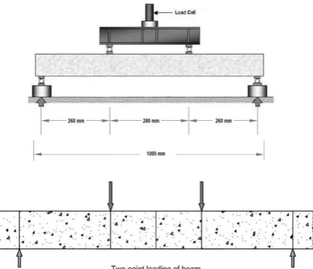
Fig. 3.1: Experimental setup for testing of beams
Table No 3.1 Deflections and Loads
Types of wraping
Avg. deflection
(
mm)
Avg. Load (KN)
Ordinary Beam 5.3 86.76
Fully wrap Beam 6.05 126.53
Parallel strip Beam 5.5 113.2
Inclined strip Beam 6.1 115.2
U-shaped Beam 5.9 119.2
IV. CONCLUSION
Based on the experimental investigations carried out on the ordinary and strengthened beam specimens using
different CFRP wrapping, the following conclusions were drawn.
The strengthening technique using wrapping system for the damaged R.C.C beam have proved to be effective.
The ultimate load carrying capacity of the strengthened beam was improved with decrease in deflections.
Considerable increase in first crack load can be achieved by using Carbon reinforced polymers. Considerable
increase in yield load can be achieved by use of Carbon reinforced polymer materials.
Table No 4.1 increase in strength
Types of wraping
Percentage increase in strength
Ordinary Beam 0%
Fully wrap Beam 31%
Parallel strip Beam 23%
Inclined strip Beam 25%
937 | P a g e
REFERENCES
[1.] Rahul kumar satbhaiya1, Shishir gupta, T.R Arora, (2013): “Rehabilitation and Strengthening of R.C.C.
STRUCTURES by using FRP composites” Vol. 3 (ISSN 2250-2459, ISO 9001:2008 Certified Journal,
[2.] Dr. GopalRai1and YogeshIndolia “Fiber reinforced polymer composites a novel way for strengthening
structures”National Conference on Repair and Rehabilitation of Concrete Structures Noida, UP, India May
6-7, 2011.
[3.] Habibur Rahman Sobuz, Ehsan Ahmed, Noor Md. Sadiqul Hasan “Use of carbon fiber laminates for
strengthening reinforced concrete beams in bending ” Publishing Limited, 2010.
[4.] D.N. Shinde, Pudale Yojana M, Nair Veena V “FLEXURAL BEHAVIOUR OF REINFORCED
CEMENT CONCRETE BEAM WRAPPED WITH GFRP SHEET” Volume: 03 Special Issue: 03 |
May-2014 | NCRIET-May-2014
[5.] Nikita Jain, Varun Kumar Sikka “Strengthening Of RC Beams with Externally Bonded CFRPs” Volume
12, Issue 2 Ver. VI (Mar - Apr. 2015), PP 139-142.
[6.] V.Ravindra&R.V.Ramkrishna,“Experimental investigation on Rehabilitation of reinforced Cement
concrete interior Beam using CFRP sheets”, International Journal of Engineering Science and Technology
(IJEST),vol 2,page no 875-881.
[7.] Muhammad Imran, Nasir Shafiq, Ibrisam Akbar “Strengthening Techniques & Failure Modes of RC Beam
Strengthened Using Fiber Reinforced Polymer” Vol.2 No.2, August 2013
[8.] M.B.S Alferjani1, A.A. Abdul Samad, Blkasem. S Elrawaff.“ Use of Carbon Fiber Reinforced Polymer
Laminate for strengthening reinforced concrete beams in shear”, Volume 2, Issue 2(February 2013),
PP.45-53
[9.] Murali G. and Pannirselvam N. “ FLEXURAL STRENGTHENING OF REINFORCED CONCRETE
BEAMS USING FIBRE REINFORCED POLYMER LAMINATE”. VOL. 6, NO. 11,
NOVEMBER 2011
[10.]Muhammad Imran, Nasir Shafiq, Ibrisam Akbar „Strengthening Techniques & Failure Modes of RC Beam
Strengthened Using Fibre Reinforced Polymer ,Vol.2 No.2, August 2013..
[11.]Ratan Kharatmol, Pankaj Sananse, Rohit Tambe, Ms.Raksha J.Khare „Strengthening Techniques &
Failure Modes of RC Beam Strengthened Using Fibre Reinforced Polymer , Volume 2, Issue 3, June 2014,