Article
Conceptual Design and Performance Optimization of a Tip Device for a
Regional Turboprop Aircraft
Ilias Lappas 1,*,+, Akira Ikenaga 2,+
1 Department of Mechanical and Aeronautical Engineering, School of Engineering, University of South Wales, Treforest Campus, Treforest CF37 1DL, UK
2 Airbus UK, BS34 7PA Filton, Bristol, England; [email protected] * Correspondence: [email protected]; Tel.: +44-01443-482565 † These authors contributed equally to this work.
Abstract:
An increasing number of aircraft is equipped with wing tip devices, which either are installed by the aircraft manufacturer at the production line or are retrofitted after the delivery of the aircraft to its operator. Installation of wing tip devices has not been a popular choice for regional turboprop aircraft and the novelty of the current study is to investigate the feasibility of retrofitting the British Aerospace (BAe) Jetstream 31 with an appropriate wing tip device (or winglet) to increase its cruise range performance, taking also into account the aerodynamic and structural impact of the implementation. To the best of the knowledge of the authors, no previous study exists which has attempted to assess the winglet retrofit of an existing aircraft type of similar size and operating profile. The optimal winglet design achieved a 2.38% increase of the maximum range by reducing the total drag by 1.19% at a mass penalty of 3.25%, as compared with the baseline aircraft configuration. Other designs were found to be more effective in reducing the total drag, but the structural reinforcement required for their implementation outweighed the achieved performance improvements. Since successful winglet retrofit programs for typical short to medium range narrow body aircraft report even more than 3% of block fuel improvements, undertaking the project of installing an optimal winglet design to the BAe Jetstream 31, should also consider a Direct Operating Cost (DOC) assessment on top of the aerodynamic and structural aspects of the retrofit.
Keywords: winglets; lift-induced drag; wing tip device; non-planar lifting surface; performance optimization; aircraft performance; regional aircraft.
Acronyms
AR Aspect Ratio
BAe British Aerospace
CFD Computational Fluid Dynamics
CPFH Cost Per Flying Hour DOC Direct Operating Cost
EMWET Elham Modified Wing Weight Estimation Technique ISA International Standard Atmosphere
MAC Mean Aerodynamic Chord MTOW Maximum Take Off Weight
MZFW Maximum Zero Fuel Weight
NACA National Advisory Committee for Aeronautics
NASA National Aeronautics and Space Administration NFLC National Flying Laboratory Centre
RPM Revolutions Per Minute
USAF United States Air Force VLM Vortex Lattice Method
WRBM Wing Root Bending Moment
1. Introduction
The aerospace industry relies on the continuous improvement of existing technologies and on the innovative development of new concepts to improve the return of investment of an aircraft design.
Many of these improvements from the airframe manufacturer’s perspective are focused on the
aerodynamic efficiency and the structural design. Aligned to the public’s increasing awareness of the
environmental footprint of the airline industry and to the uncertainty in airline’s revenue, stemming from the fluctuating oil-prices, there has been a push towards developing eco-friendly designs.
Governmental bodies and the aerospace industry have set targets and roadmaps to improve current airframes, develop new technologies in powerplant design and air traffic management to reduce the
environmental impact of air transportation systems. According to a study commissioned by the Department of Transport[1], winglets are a valid NOx and CO2 abatement technology which can
result in a reduction of 2% in fuel burn with relatively small capital investment and modification cost.
A similar conclusion has been reached at the study of Farriers and Eyers[2], in which winglets are
considered as an evolutionary airframe technology to provide an overall aerodynamic advantage to
previous and current generation airframes.
The BAe Jetstream 31 is a regional turboprop derived from the earlier Handley Page HP.137
Jetstream. Designed for regional routes, it is a small twin-engine turboprop with pressurized fuselage carrying from 12 to 19 passengers. The Jetstream 31 was designed for a niche market aimed at airlines
wishing to offer regional commuter service at higher speeds between small regional airports. There are few manufacturers offering an aircraft of similar specification and most other aircraft operating
Figure 1. Regional commuter market overview (Data sourced from the world wide web, not an exhaustive list of all operating types. Year of maiden flight in brackets).
Figure 1 shows a representative market overview which compares the range versus Maximum Take Off Weight (MTOW) for various aircraft which are still in service and offer a capacity of 19
passengers. It is observed that for all aircraft, bar the DHC-6 Twin Otter, first flight was nearly 40 years ago. The DHC-6 offers a very similar range to the Jetstream 31 with an 1 ton lower MTOW and
has a very similar range performance in comparison to the Chinese Harbin Y-12. The Jetstream 31 would have outperformed the Y-12 in terms of range with a 6% increase of its current range.
Furthermore, the only aircraft of Figure 1 currently in production is the DHC-6 Twin Otter and a winglet retrofit might provide an incentive to maintain the Jetstream 31 in service for longer, if proved to be worth undertaking. It is considered that the incentive to keep the Jetstream 31 in service is
significant, since there are only a few options for an aircraft of similar characteristics. The widespread availability of the Jetstream 41, a stretched and re-engined variant, can also provide common spare
parts to the Jetstream 31 to sustain the existing fleet, thus justifying further investment into a Jetstream 31 airframe with performance improvements.
A wingtip retrofit option entails maintaining the original wing shape and structure as close as possible, while achieving a performance improvement with the installation of an efficient tip device.
There are differing views on the feasibility of wing tip treatments for short domestic flights, as the aerodynamic improvements may not have a net fuel usage improvement (or range trade-off) due to the multidisciplinary nature of the modification. The design and implementation of winglets has been
to this day a challenging multidisciplinary effort [3].
1.1 Induced drag reduction techniques
The induced drag coefficient 𝐶𝐷,𝑖 is defined as:
𝐶𝐷,𝑖= 𝐶𝐿2
𝜋𝑒𝐴𝑅 (1)
in which 𝐶𝐿 is the coefficient of lift, e is the Oswald efficiency factor and AR is the aspect ratio. In
(infinite AR) and by optimising the spanload to match the elliptical distribution (e=1). Unfortunately, the induced drag reduction does not necessarily translate directly to better aircraft performance in
terms of range increase or fuel saving when compared against the baseline aircraft configuration, as is the case for a retrofit study. A span extension reduces induced drag and increases wetted area, therefore increasing profile drag, hence, there exists a crossover point at which increasing span is no
longer beneficial.
From the structural perspective, the ideal spanload may not result in an efficient structural design
due to the forces and moments experienced by the structure. As a certain proportion of the wing structural weight is related to resisting bending stress, an increase of bending moment is considered
to increase wing weight [4]. The aerodynamic efficiency resulting from induced drag reduction should therefore be analysed in the context of both the parasitic drag and the structural analysis
considerations for the configuration in question, and their overall effect on the aircraft performance needs to be evaluated. The aerodynamic and structural objectives work against each other and a
meta-objective becomes necessary to evaluate the effects at the aircraft level rather than the
component level. After Prandtl’s [5] formulation of the lifting line theory and the associated induced
drag, there have been practical studies [6, 7] on minimizing induced drag by studying the effects on
spanload (spanwise distribution of lift) and accounting for the bending moment experienced by the wing as a measure of the structural impact.
1.2 Non-planar devices
Even before the Wright Brother’s first powered flight in 1903, English aerodynamicist Lanchester
has patented what is now known as end-plates and described the function of the truncated wings
fitted with vertical capping wings as ‘to minimise the loss of energy due to air circulation around the wind
(sic: wing) extremities’ [8]. More recently, Whitcomb [9] has studied the use of smaller wing extensions
attached to the wing tips on transonic aircraft and called them ‘winglets’. Further studies have been
carried out [10-16], in which a various methods were used to assess the aerodynamics and the assumed structural impact of adding non-planar span extensions, though with no clear consensus
regarding the advantage of a non-planar extension over planar extensions. Assessing the aerodynamics of the different wing options, several methods were used, from fully numerical [10] to
purely experimental [9,11]. As highlighted by Asai [12], the computer models which have been used to analyse drag were lacking viscous drag measurements. The most widely used method in assessing
the structural impact measures the Wing Root Bending Moment (WRBM), but that does not accurately represent the loads transmitted on the structure such as torsion or inertia moments. Elham
and Van Tooren [15] have addressed this issue by using medium fidelity tools but still allowing for minimised computational cost when analysing a wide design space.
1.3 Winglet studies on various aircraft platforms
Typical missions flown by large transonic aircraft include a lower stratospheric cruise segment
lasting an average of 90% of the block time in which induced drag accounts to about 25% of total drag [17]. There is a limited number of studies on wingtip implementation or research for relatively smaller
The United States Air Force (USAF) has commissioned the National Research Council to evaluate its aircraft inventory and identify those aircraft that may be good candidates for winglet
modifications [18]. The C-130 turboprop tactical airlifter has been evaluated as well, but concerns were highlighted on the suitability of the aircraft for a winglet retrofit, as the wing is already very efficient due to its relatively high aspect ratio (AR = 10.1) and non-swept wings with low loaded
wingtips. These two factors compounded by the short operating missions and the low flight altitudes, minimize the benefits of winglets, as their optimum flight condition is in higher altitudes for higher
wingtip loadings and longer cruise segments in lower density air.
Lehmkuehler and Wong [19] have designed winglets for the Fairchild Merlin III turboprop 8-seat
commuter aircraft and their CFD analysis has shown a 5% gain in the Lift to Drag ratio (L/D) over the reference wing. The study has focused on the aerodynamic design using CFD, without
performing a detailed study on the structural impact of the winglet. Nicolosi et al. [20] have designed a twin-engine 11-seat commuter aircraft incorporating aerodynamic optimisation of the wing using
winglets with the purpose of increasing take-off, climb, approach and landing performance. Della Vecchia [21] has developed methods for aerodynamic design and optimisation aimed at developing a new regional turboprop aircraft using the ATR 72 aircraft as a baseline. His configuration has used
optimised winglets which have showed an improved L/D, including shorter take-off runs, faster rate of climb, higher operating ceiling and lower fuel consumption for a given mission.
The literature review yielded no previous study on an aircraft similar in configuration to BAe Jetstream 31. Lehmkuehler et al. [19] and Della Vecchia [21] have developed winglets for a smaller
and larger aircraft respectively in terms of MTOW, with limited consideration on the structural effects of a tip device. The structural impact was evaluated by comparing WRBMs, and this is an approach
that has been considered as not capturing all the potential structural considerations [12, 14, 15]. The practical effects of the improvements achieved by the use of winglets have been summarised by Conley [22], and Dees and Stowell [23] as:
• Decrease in fuel burn (or increase in range).
• Increase in flight ceiling.
• Reduced take-off runs.
• Increased time between engine maintenance.
2. Methodology
2.1. Geometry modelling
The aerodynamic effects of winglets and their advantages have been a contentious topic with no
clear winner in terms of drag reduction compared to a planar extension, with most studies evaluating
solely the induced drag and ignoring viscous effects. Therefore, the design scope of the present study
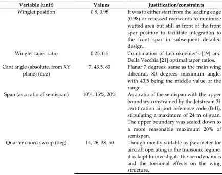
includes planar extensions as well as non-planar devices based on Whitcomb’s winglet. Figure 2 and
Table 1 illustrate the design variables that have been chosen for evaluation, together with their
Figure 2. Winglet parameters terminology
Table 1. Design variables and evaluated values (1296 design points).
Variable (unit) Values Justification/constraints
Winglet position 0.8, 0.98 It was to either start from the leading edge
(0.98) or recessed rearwards to minimize wetted area but still in front of the front spar position to facilitate integration to the front spar in subsequent detailed design.
Winglet taper ratio 0.25, 0.5 Combination of Lehmkuehler’s [19] and
Della Vecchia [21] optimal taper ratios. Cant angle (absolute, from XY
plane) (deg)
7, 43.5, 80 Planar 7 degrees, same as the main wing
dihedral. 80 degrees maximum angle, with 43.5 being the middle value of the range.
Span (as a ratio of semispan) 10%, 15%, 20% As a ratio of the semispan with the upper
boundary constrained by the Jetstream 31 certification airport reference code (B-II), stipulating a maximum of 24 m of span. The upper boundary was scaled down to a more reasonable maximum 20% of semispan.
Quarter chord sweep (deg) 14, 26, 38, 50 Though mostly suitable as parameter for
Toe-out (deg) -4, -2.5, -1 Toe-out angle dictated by the local lift coefficient requirement.
Twist (deg) -4, -2.5, -1 Twist controls the winglet spanload [21].
A Design of Experiment was set featuring a full factorial on the design parameters, yielding 1296 design points. The analysis of the design points was automated using Python (v2.7.13, released
on 17 December 2016). As the study compares a reference and project aircraft configuration, an initial reference model was created, verified and validated. The reference model was then modified with
specific design values to yield the project aircraft for each design point. OpenVSP (v3.10, released on 8 January 2017) was used for the geometry modelling of the aircraft. Benefits from using OpenVSP
are the existing integration of the VSPAero aerodynamic solver based on the Vortex Lattice Method (VLM), which was used for the purposes of this study, as well as the capability of meshing outputs for various finite element analysis packages. The geometry information has been obtained from
aircraft manufacturer data [24] and previous simulation work performed by Cooke [25]. Aircraft components not modelled for this study are: nacelles, propellers, aft fuselage vertical strakes, landing
gear doors, belly fairing, fuselage-wing root fairing, vertical tail plane fillet. Actuator discs were modelled instead of propellers.
2.1.1 Reference model
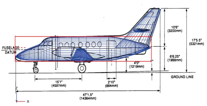
Figures 3, 4 and 5 show the reference aircraft model overlaid on the aircraft maintenance manual
views.
Figure 5. Reference model top view
2.1.2 Wing
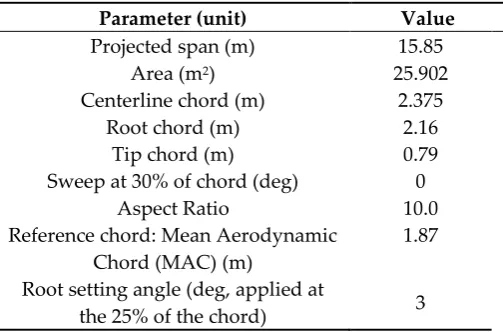
The main wing was modelled as two panels, each one extending from the wing tip to the wing root position. The local axis of the wing is defined as the leading edge at the centreline. The 6-digit NACA
aerofoil coordinates were generated in OpenVSP and the specific ‘a’ value defining the laminar
proportion of the chord required for these types of aerofoil was set to 0. The dihedral was assumed to be specified along the mean camber line of the wing (planar surface created from each wing section
data). The geometrical reference data for the wing is provided at the Table 2.
Table 2. Geometrical reference data for the wing.
Parameter (unit) Value
Projected span (m) 15.85
Area (m2) 25.902
Centerline chord (m) 2.375
Root chord (m) 2.16
Tip chord (m) 0.79
Sweep at 30% of chord (deg) 0
Aspect Ratio 10.0
Reference chord: Mean Aerodynamic Chord (MAC) (m)
1.87
Root setting angle (deg, applied at
the 25% of the chord) 3
Two extra panels were added to the wing: one transition panel after the wingtip and a winglet
panel. The purpose of using the transition panel was to allow the application of a toe-out angle to the wingtip base. Applying the toe-out angle at the wingtip without this additional transition panel
characteristics. Furthermore, on a retrofit study, the inner wing geometrical shape is assumed to be kept constant or it would become a wing redesign project. For the lofting of the transition panel and
winglet, an aerofoil designed specifically for low Reynolds number winglets was chosen, the PSU-94-097 winglet aerofoil designed by Maughmer et al [26], which has been also analysed by Della Vecchia [21]. The transition panel was specified with a constant span of 0.1 m (independent of the
winglet span) and the dihedral value of this transition panel as 67% of the winglet cant angle.
2.1.3 Fuselage
The fuselage was modelled with the ‘FUSELAGE’ component with a circular section for the center
section between the cockpit and the exit door and elliptical sections were used to model the cockpit,
nose cone and tail cone. The geometrical reference data for the fuselage is shown at the Table 3.
Table 3. Geometrical reference data for the fuselage.
Parameter (unit) Value
Circular maximum diameter (m) 1.981
Length (m) 13.347
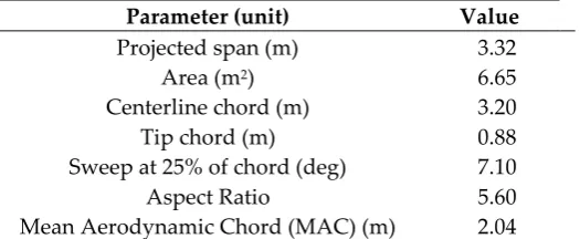
2.1.4 Vertical and horizontal tailpanes.
Both vertical and horizontal tail planes “WING” sections were modelled with the same method
as the main wing, with the vertical tailplane differing in that it was rotated 90 degrees to align with
the Z axis. The aerofoils for the tail planes were generated in the OpenVSP NACA 4-digit aerofoil generator tool. The geometrical reference data for the horizontal and vertical tailplanes are presented
at the Table 4 and 5 respectively.
Table 4. Horizontal tail plane geometrical reference data.
Parameter (unit) Value
Projected span (m) 6.60
Area (m2) 7.80
Centerline chord (m) 1.676
Tip chord (m) 0.6855
Sweep at 25% of chord (deg) 7.10
Aspect Ratio 5.60
Mean Aerodynamic Chord (MAC) (m) 1.181
Root aerofoil NACA 0012
Tip aerofoil NACA 0010
Dihedral (deg) 0
Table 5. Vertical tail plane geometrical reference data.
Parameter (unit) Value
Projected span (m) 3.32
Area (m2) 6.65
Centerline chord (m) 3.20
Tip chord (m) 0.88
Sweep at 25% of chord (deg) 7.10
Aspect Ratio 5.60
Root aerofoil NACA 0012
Tip aerofoil NACA 0010
2.2. Aerodynamic analysis
VSPAero, which is an integrated aerodynamic tool of OpenVSP (v3.10, released on 8 January 2017), has been used. The 3D potential flow tool offers both VLM and panel implementations, with VLM
simplifying the geometry to mean camber lines and panel method representing the surface of the aircraft with vortex sheets. The VLM has been chosen, having considered the computational cost and
the number of designs to be analysed. The outcomes of the method were validated using published flight test data (the validation is analysed at 2.3 below).
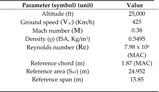
The cruise conditions of the aircraft model are shown at the Table 6.
Table 6. Cruise reference conditions.
Parameter (symbol) (unit) Value
Altitude (ft) 25,000
Ground speed
(V
∞)
(Km/h) 425Mach number
(M)
0.38Density (ρ) (ISA, Kg/m3) 0.5495
Reynolds number
(Re)
7.98 x 10⁶(MAC)
Reference chord (m) 1.87 (MAC)
Reference area (Sref) (m) 24.952
Reference span (m) 15.85
VSPAero (v3.10, released on 8 January 2017) does not predict viscous effects on lift and drag. XFoil
(v6.99, released on 23 Dec 2013) was used to predict the maximum viscous lift coefficient CL at the
operating conditions to constrain wing sectional lift coefficient 𝐶l to 1.49. At the cruise condition:
𝐶
𝐿𝑐𝑟𝑢𝑖𝑠𝑒=
𝑊𝑐𝑟𝑢𝑖𝑠𝑒 1 2𝜌𝑉∞2𝑆 𝑟𝑒𝑓
(2)
The weight of the aircraft at cruise Wcruise, can be approximated as [27]:
𝑊𝑐𝑟𝑢𝑖𝑠𝑒= √(𝑀𝑇𝑂𝑊) 𝑥 (𝑀𝑍𝐹𝑊) (3)
From (2) and (3), after substituting the approved values [28] for the MTOW and the Maximum Zero Fuel Weight (MZFW), it is calculated that:
𝐶𝐿𝑐𝑟𝑢𝑖𝑠𝑒= 0.66 (4)
The actuator disks modelled in lieu of propellers, modify the streamlines downstream of the disk to simulate prop-wash and the contraction of streamlines. The model in VSPAero is based on
Conway’s [29] actuator disk theory and it has been verified and validated for NASA projects such as
determined by the thrust coefficient, the power coefficient and the RPM, for which the default values in VSPAero of 𝐶T = 0.4, 𝐶Power = 0.6 and 2000 RPM, respectively, have been used.
The Certification Specification-25 (Large Aeroplanes) [31] specifies the certification requirements for which the sizing loads of the wing are derived from flight manoeuvre and gust conditions. The critical sizing condition assumed for this study is 2.5g pull-up manoeuvre at cruise condition and
VSPAero was run for both 1g and 2.5g conditions.
2.3. Validation of Reference Aerodynamic Model
Published flight test data for the Jetstream 31 of the National Flying Laboratory Centre (NFLC) [32] has been used to validate the VSPAero model. The actual flight test data has been best
represented by the following equations for the lift and drag coefficients:
𝐶𝐿= 0.3305 + 0.1052𝛼𝑏 (5)
𝐶𝐷 = 0.0376 + 0.0607𝐶𝐿2 (6)
The applicability of the equations (5), (6) is restricted to the linear portion of aerodynamics since the NFLC aircraft is not allowed to stall, hence the polars of the VSPAero model were only estimated for up to 10 degrees, while a design flight condition was chosen which mostly matches the theoretical lift coefficient value of 0.66 calculated above. The lift curve slope was found to be in good agreement to the flight test data and a very good trend on the total drag model has been observed as well for low angles of attack, slightly diverging for values higher than 7 and up to the 10 degrees. Table 7 shows the comparison between the predictions of the model and the published flight test data.
Table 7. Comparison with the flight test data [32].
Parameter Lawson et
all [32] VSPAero prediction for the developed model % difference
Lift curve slope 0.1052 0.1101 4.66
Lift coefficient for zero angle of attack 0.3305 0.3323 -2.48
Lift coefficient at 3 degrees angle of attack 0.6461 0.655 -1.4
Zero lift drag coefficient 0.0422 0.0433 0.26
Drag coefficient at 3 degrees angle of attack 0.0629 0.0641 1.78
L/D at zero angle of attack 7.472 6.985 -6.52
L/D at 3 degrees angle of attack 10.27 10.23 -0.4
Maximum L/D 10.5 10.78 2.66
2.4. Structural Sizing
the wing planform and the related aerofoils. The technique achieves high levels of accuracy (average error on the total wing weight is consistently lower than 2%) and design sensitivity with low computational cost. By using the student version of EMWET the accuracy of the results might slightly deviate from the mentioned above average error [35]. Approved values from the aircraft Type Certificate [28] and its technical drawings [24] have been used as inputs to model the structure.
2.4.1. Reference model structural validation
Published weight data for the Garret-TP331-10 engine [36] has been used. Structurally, the wingbox was simplified to two main spars (front and rear, the middle spar has been ommited). The fuel tank was modelled to occupy the complete wingbox volume enclosed between the front and rear spars. Rib pitch was approximated to 0.5 m per rib bay with the stringers across the upper and lower
covers to have an efficiency of 0.96 for ‘Z’ type stringers [37]. The material defined for all panels is alluminium alloy 7075-T6. A kink was identified in the front spar after the powerplant and the structure was defined in four sections: centre, root, kink and tip. The calculated structural weight for
the reference wing is 889.1 Kg, which is 12.23% of the MTOW. By applying Elham’s [37] wing weight
estimation formula, which is based on statistical data and uses a power equation:
𝑊𝑤𝑖𝑛𝑔 (𝐸𝑙ℎ𝑎𝑚 𝑒𝑞.)= 68.22𝑥10−4𝑀𝑇𝑂𝑊1.25 (7),
a wing weight Wwing of 928.54 Kg is estimated, which is 12.63% of the MTOW. This 0.4% diffence
can be attributed to the different aerodynamic methods used, as well as to the fact that the power equation does not contain any aircraft of comparable MTOW to the Jetstream 31. The smallest aircraft used in the validation of the power equation was the Fokker F50, an aircraft nearly three times heavier than the Jetstream 31. Furthermore, the student version of EMWET used for the calculations relies on a different, simplified regression analysis when compared to the full version. Statistical data from Kundu [38] approximates the weight of the wing as 10-12% of MTOW for mid-sized twin engine turboprop aircraft, an estimate which is in agreement with the calculated value for the developed model.
2.4.2. Project model structural design.
Figure 6. Reference model top view
2.5. Aircraft Performance Assessment
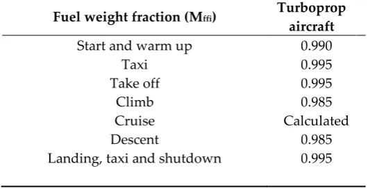
The methodology followed by Mariens [35] and introduced by Roskam [39] is used to calculate the required fuel for the mission of the aircraft. This methodology uses Breguet range equation, together with statistical factors which estimate the fuel weight of the typical segments of the aircraft
flight mission. The statistical factors are shown at the Table 8.
Table 8. Fuel fraction for each segment of a typical flight mission, as suggested by Roskam [39] .
Fuel weight fraction (Mffi) Turboprop aircraft
Start and warm up 0.990
Taxi 0.995
Take off 0.995
Climb 0.985
Cruise Calculated
Descent 0.985
Landing, taxi and shutdown 0.995
Each fuel weight fraction Mffi indicates the ratio of the total aircraft weight at the end of the flight segment to the total aircraft weight at the beginning of the segment. Thus, the total fuel weight
fraction defines the consumed fuel as a ratio of the total aircraft weight at the end of the flight mission to the total aircraft weight at the beginning. The total fuel weight fraction is also equal to the product
M
𝑓𝑓= ∏
𝑀
𝑓𝑓𝑖= 1 −
𝑊𝑓𝑢𝑒𝑙
𝑊𝑡𝑎𝑘𝑒 𝑜𝑓𝑓
𝑛
𝑖=1
(8)
From Raymer [40], the propulsive efficiency of the model was assumed as np = 0.8, while the
specific fuel consumption is equal to cp = 9.344 x 10⁻⁵ Kg/[(Watt) x (sec)] [36]. Table 9 provides a
synopsis of the weight data used at the performance calculations for the Jetstream 31.
Table 9. Synopsis of the weight data for the Jetstream 31 (Cross-checked from [28] and [41]).
Weights Value (Kg)
Reference wing 449.52
MTOW 7350
MZFW 6350
Maximum payload 1935
Maximum Fuel 1491
OEW 4415
The Payload-Range diagram of the deeloped model is shown at Figure 7.
The specific payload-range point is defined as the cruise range for a specified payload. Assuming 19 passengers at 94 Kg per passenger (including luggage), the specified payload is 1786 Kg with a
calculated cruise range of 1018.15 Km for the reference model aircraft. The specific design point was then assessed for each winglet permutation, resulting in L/Dproject and Mffcruise(project), the latter term
being dependent on the OEW. The variation of the fuel weight affects the range of the aircraft;
therefore, the structural impact on range can be assessed as well.
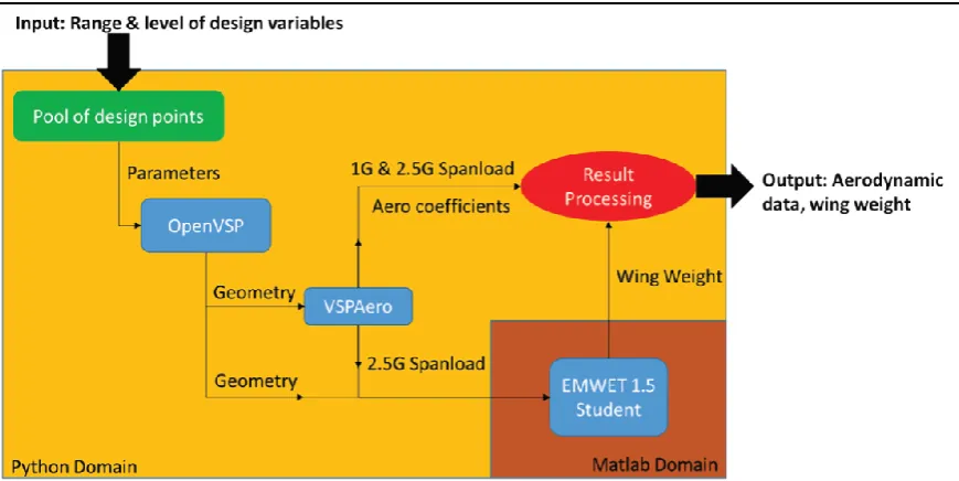
2.6. Python Integration Framework
Python (v2.7.13, released on 17 December 2016) has been used to create an automated integration framework. Python environment was used to write OpenVSP script files to apply the design variables written also by Python from a separate file. The data generation workflow was split into the following major Python functions :
• OpenVSP and VSPAero Runner: Create a pool of design points for the desired range of
variables. This is then fed to OpenVSP for each design point in an AngelScript++ input file for OpenVSP coontaining case specific design parameters. The geomerty generated by OpenVSP was then read in VSPAero and executed to calculate aerodynamic data for 1 and 2.5 g conditions.
• EMWET input file parsing: As EMWET requires the geometry, spanload and the quarter
chord pitching moment, the VSPAero output files were parsed and written onto the EMWET initialization and load files. Each individual EMWET case was appended onto a Matlab * .m script that could then be run from Matlab. To process the results, two functions were developed in Python to ultimately output a comma-separated values file in ASCII for data visualization and allow oprimisation work in the future.
• Parsing of VSPAero aerodynamic coefficients and associated wing weight and joining each
case input to its output.
• Writing case input and output in a *.csv file.
Figure 8 illustrates the flowchart of the implementation process.
3. Results
Following the first iteration, winglet taper ratio was found to have negligible effects on both aerodynamic efficiency and wing weight and it was subsequently removed, thus the design points were reduced to 648. Figure 9 is the plot of the calculated values of total drag ratio CD/CD ref and wing
weight ratio W/Wref of all the design points. The aircraft reference values are CD ref = 0.0641 and
Wref = 449.55 Kg.
Figure 9. Design point values for drag and wing weight ratio.
The non-convergence area highlighted at the Figure 9 was isolated and removed in subsequent analysis as convergence errors were identified during the aerodynamic calculations. Drag savings range from 0.05% to 5.105% at a weight penalty of 3% to a significant 35%. Comparable drag savings are obtained from a wide range of structural weights, which shows the importance of an optimised structure. The study focused at cant and span, as they are the most significant drivers in terms of aerodynamic efficiency and weight.
Figure 10. WRBM vs wing weight
3.1. Cant angle effects
Figure 11. Cant angle distribution at the design space.
Although the designs were constrained by CLcruise, resulting in equal aerodynamic force and
moment distribution, at lower cant angles the bending load increases due to the increased bending arm, spanwise distance from the root. Furthermore, highly canted surfaces do not produce as much
‘lift’ in its traditional sense measured as a force in the z-axis, instead they will contribute more to a
‘sideforce’, eventhough the net force normal to the wing surface is constant. Since EMWET only uses lift force in the z-axis as an input, the net bending effects might not have been fully accounted for the 80 degrees designs during the structural sizing, as most of the force is perpendicular to the lift (normal to the wing surface), therefore providing an explanation for the insensitivity to the weight change. Another simplification assumed with EMWET was modelling the wing and the winglet as a single unity, resulting in the tool adding material across the span of the wing. The tool is programmed to add material inboard whenever possible to minimise outboard stress concentrations and take
advantage of the root section’s higher second moment of area to resist bending loads.
3.2. Span effects
Figure 12. Winglet span effect on design point distribution.
Figuge 12 is is the same as Figure 11 with shaded iso-span regions of 0.1, 0.15 and 0.2. For each cant angle, the drag savings are higher for increasing span ratios, incurring a higher weight penalty. For 80 degree cant, the distribution of points appear to be near vertical with each span ratio stacking
in columns against each other. For each span “column” the range between the highest and lowest
drag range increase as span increases. At 0.1 span ratio, the 7 degree and 43.5 degree columns result
in the same behaviour albeit with an offset in the X-axis with the 7 degree “column” resulting to be
heavier and an offset in the Y-axis with decreased drag reduction effects; The same behaviour can be observed for the 0.15 and 0.2 span ratios.
3.3. Pareto front.
Figure 13. Pareto front in the design space.
3.4. Optimised winglet design.
When assesing the best cruise range for the design points, a Pareto oprimised design point for maximum cruise range was identified with a drag reduction of 1.19% and weight increase of 3.25%. The optimal winglet parameters were found to be the following (Table 10):
Table 10. Optimal winglet parameters.
Parameters Value
Cant 80 (deg.)
Span 0.1
Sweep 26 (deg.)
Toe-out -1 (deg.)
Twist -1 (deg.)
CD/CDref -1.186%
W/Wref 3.25%
Figure 14. Isometric view of the optimal winglet.
The optimal winglet configuration achieved a cruise range increase of 2.38%. The overall effect of the optimal configuration to the payload-cruise range diagram is shown at the Figure 15.
Regarding the aerodynamic characteristics of the optimal winglet configuration, the lift coefficients are nearly identical to the reference configuration. Overall drag is reduced though, thus achieving an average increase of 7.2% for the lift to drag ratio accros the polar. The structural impact of the optimal winglet configuration was isolated to the upper and lower skins without any changes to the spars. The reinforecements required on the upper skin cover most of the span of the wing, while at the lower skin cover just over half of the wing, all in all resulting in a total weight increase of 14.61 Kg/wing (3.25% increase).
4. Discussion
Similar to the considerations for which the C-130 aircraft type was not recommended as a potential platform for winglet retrofit [18], the Jetstream 31 has a relatively high aspect ratio of 10, non-swept wings, it flies at relatively low cruise altitudes and has the typical range of a regional turboprop aircraft. The combination of those design and operational parameters does have an effect to the expected winglet benefits. Work by Gautham and Bibin [42] suggests that the use of winglets improves the aerodynamic efficiency at all aspect ratios. However, the key finding of their work is that there exists an optimal aspect ratio at which winglets offer maximum effectiveness for a given flight condition. From an operational point of view, their work encourages retrofitting the aircraft with winglets, but at the same time it underlines the importance of incorporating the winglet design and optimization as an integral part of the early conceptual design of a new aircraft platform.
The absence of commercial operational data for aircraft of similar size and engine types as the Jetstream 31 sets some validation challenges to the current study. One study of a similar, though conceptual, aircraft type [21] shows no considerable benefits for the cruise condition when using an optimized winglet that has a height of 10% of the wing semi-span and a cant angle of 80 degrees. Instead, [21] reports significant benefits for the takeoff, approach and landing segments of the flight since induced drag is the dominant drag component at those stages and since turboprop aircraft will spend typically a higher percentage of their mission time climbing and approaching than other passenger aircraft which operate at higher subsonic speeds and are powered by turbofan engines.
For a typical passenger aircraft configuration flying at higher subsonic speeds than the Jetstream 31 of the present study, significant aerodynamic and structural benefits have been observed for the
cruise condition by using the ‘curved winglet concept’ suggested by Gueraiche and Popov [43]. Their proposed winglet design is considered a fair compromise between classic, low cant angle Whitcomb winglets and ‘lifting’ large cant angle winglets. Εliminating the constraints set by the cant angle,
paves the way to the exploration of ‘variable cant angle’ winglet concepts which, according to Guerrero et al [44], can potentially enable aircraft designs to achieve optimal performance at a wide range of angle of attack values.
5. Conclusion
With reported block fuel improvements of more than 3% for ranges of more than 700 nm when installing winglets to the Boeing 737-800 [23], the installation of the optimal winglet design of the current study to the Jetstream 31, might not be considered as cost efficient. However, the decision of retrofitting should not take into consideration only the aerodynamic and structural aspects and it should typically also consider a DOC assessment, for which a method followed at [45] is suggested. A study [46] which has identified a relationship amongst the Cost Per Flying Hour (CPFH) and aircraft design parameters, has shown that the two design variables which contribute most to the CPFH are the maximum specific fuel consumption and the aircraft empty weight, thus it is almost certain that a winglet retrofit will influence the operating cost of the aircraft.
Author Contributions: The authors contributed equally to the preparation of the article.
Acknowledgments: The authors would like to thank Luuk van der Schaft and Dr Odeh Dababneh for contributing with ideas and advice. Special thanks as well to Dr Ali Elham who has provided the
student version of ‘EMWET’.
Funding: This research received no external funding.
Conflicts of Interest: The authors declare no conflicts of interest.
References
1. Morris, J.; Rowbotham A.; Morrell, P. et al. UK Aviation: Carbon reduction futures; Final report to the Department for Transport, UK, July 2009.
2. Farries, P.; Eyers, C. Aviation CO2 emissions abatement potential from technology innovation; Office of Climate Change, UK, October 2008.
3. Streit, T; Himisch, J; Heinrich, R.; Nagel B.; Horstmann, K. et al. Design of a retrofit winglet for a transport aircraft with assessment of cruise and ultimate structural loads . In: Tropea, C; Jakirlic, S; Heinemann, H.J. et al (eds). New results in numerical and
experimental fluid mechanics VI. Notes on Numerical Fluid Mechanics and Multidisciplinary Design (NNFM), 2007, 96, 62-70, Springer, Berlin, Heidelberg.
4. Prandtl L. Uber TragflUgel des Kleinsten Induzierten Widerstandes. Zeitschrift fur
Flugtechnikund Motor luftschiffahrt, 24 Jg. 1933. (Reprinted in – W. Tollmien , H. Schlichting,
H. CSrtler (eds)Gesaimnelte Abhandlungen.
5. Prandtl L. Application of modern hydrodynamics to aeronautics; NACA technical report No. 116,
National Advisory Committee for Aeronautics: Washington DC, USA, Jan 1923.
6. Jones R.T. The spanwise distribution of lift for minimum induced drag of wings having a given lift
and a given bending moment; NACA technical note No. 2249, National Advisory Committee for Aeronautics: Washington DC, USA, Dec 1950.
7. Hoerner S. Aerodynamic shape of the wing tips; United States Air Force technical report No.
5752; Wright-Patterson Air Force Base, Dayton, Ohio, USA, 1952.
8. Jarrett P.F.W. Lanchester and the great divide. Journal of Aeronautical History.2014. Available
online: https://www.aerosociety.com/publications/jah-fw-lanchester-and-the-great-divide/
(accessed on … May 2019)
9. Whitcomb R.T. A design approach and selected wind tunnel results at high subsonic speeds for wing-tip mounted winglets; Technical Note TN-D-8260; NASA Langley Research Center: Hampton,
10. Heyson, H.H; Riebe, G.D; Fulton, C.L. Theoretical parametric study of the relative advantages of winglets and wing-tip extensions; NASA technical memorandum TM X-74003; NASA Langley
Research Center: Hampton, VA, USA, Sep 1977.
11. Jones, R.T.; Lasinski, T.A. Effects of winglets on the induced drag of ideal wing shapes; NASA technical memorandum TM-81230; NASA Ames Research Center: Moffett Field, CA, USA,
Sep 1980.
12. Asai, K. Theoretical considerations in the aerodynamic effectiveness of winglets. Journal of
Aircraft. 1985, 22 (7), 635-637.
13. Kroo, I.; McMasters, J.; Smith, S.C. Highly nonplanar lifting systems. In Proceedings of:
Transportation Beyond 2000: Technologies Needed for Engineering Design, NASA Langley Research Center, Hampton, VA, USA, 26-28 September, 1995.
14. Ning, S.A.; Kroo, I. Tip extensions, winglets and C-wings: Conceptual design and
optimization. In Proceedings of the 26th AIAA Applied Aerodynamics Conference, Honolulu,
Hawaii, USA, 18-21 August 2008.
15. Elham, A.; van Tooren, M.J.L. Winglet multi-objective shape optimization. Aerospace Science
and Technology. 2014, 37, 93-109.
16. Khosravi, S.; Zingg, D.W. A numerical optimization study on winglets. In Proceedings of the
15th AIAA/ISSMO Multidisciplinary Analysis and Optimization Conference, Atlanta,
Georgia, USA, 16-20 June 2014.
17. Jobe, C.E. Prediction of aerodynamic drag; Technical memorandum AFWAL-TM-84-203; Flight
Dynamics Laboratory: Wright-Patterson Air Force Base, Ohio, USA, July 1984.
18. National Research Council. Assessment of wingtip modifications to increase the fuel efficiency of
Air Force aircraft; The National Academies Press: Washington, DC, USA, 2007.
19. Lehmkuehler, K.; Wong, K.C. Winglet design for a Fairchild Merlin III using CFD analysis.
In Proceedings of the AIAC14 14th Australian International Aerospace Congress, Melbourne,
Australia, 28 February- 3 March 2011.
20. Nicolosi, F.; Della Vecchia, P.; Corcione, S. Design and aerodynamic analysis of a twin-engine
commuter aircraft. Aerospace Science and Technology.2015, 40, 1-16.
21. Della Vecchia, P. Aerodynamic guidelines in the design and optimization of new regional
turboprop aircraft. Aerospace Science and Technology.2014, 38, 88-104.
22. Conley, N. Winglet toe-out angle optimization for the Gates Learjet longhorn wing. Journal
of Aircraft,1980, 17(12), 851-855.
23. Dees, P.; Stowell, M. 737–800 winglet integration; SAE Technical Paper 2001-01-2989, 2001.
24. British Aerospace. Jetstream 31 Maintenance Manual, United Kingdom, 1982.
25. Cooke, A.K. A simulation model of the NFLC Jetstream 31; College of Aeronautics Report No.
0402; Cranfield University, UK, 2006. Available online :
https://dspace.lib.cranfield.ac.uk/handle/1826/7623
26. Maughmer, M.D.; Swan, T.S.; Willits, S.M. Design and testing of a winglet airfoil for
low-speed aircraft. Journal of Aircraft, 2002, 39(4), 654-661
27. Torenbeek, E. Advanced Aircraft Design, Conceptual Design, Analysis and Optimisation of
Subsonic Civil Airplanes. John Wiley and Sons Ltd, West Sussex, UK, 2013, p.410.
28. European Aviation Safety Agency (EASA). Type Certificate Data Sheet Jetstream 3100/ 3200
https://www.easa.europa.eu/documents/type-certificates/aircraft-cs-25-cs-22-cs-23-cs-vla-cs-lsa/easaa191#main-content (accessed on….2019)
29. Conway, J.T. Exact actuator disc solutions for non-uniform heavy loading and slipstream contraction. Journal of Fluid Mechanics, 1998, 365(01), 235-267.
30. Stoll, A.M. Comparison of CFD and experimental results of the LEAPTech distributed electric
propulsion blown wing. In Proceedings of the 15th AIAA Aviation Techonlogy, Integration
and Operations Conference, AIAA Aviation forum (AIAA 2015-3188), Dallas, TX, USA,
22-26 June, 2015.
31. European Aviation Safety Agency (EASA). Certification Specification-25.331-341 (Large
Aeroplanes), EASA, Cologne, Germany. Amendment 3, 19 Sep 2007. Available online:
https://www.easa.europa.eu/sites/default/files/dfu/CS-25_Amdt%203_19.09.07_Consolidated%20version.pdf
32. Lawson, N.J.; Jacques, H.; Gautrey, J.E.; Cooke, A.K.; Holt, J.C.; Garry, K.P. Jetstream 31
national flying laboratory: Lift and drag measurement and modelling. Aerospace Science and
Technology, 2017, 60, 84-95.
33. Dababneh, O.; Kipouros, T. A review of aircraft wing mass estimation methods. Aerospace
Science and Technology, 2018, 72, 256-266
34. Elham, A.; La Rocca, G.; van Tooren, M.J.L. Development and implementation of an
advanced, design-sensitive method for wing weight estimation. Aerospace Science and
Technology, 2013, 29, 100-113.
35. Mariens, J.; Elham, A.; van Tooren, M.J.L. Influence of weight modelling on the outcome of
wing design using multidisciplinary design optimisation techniques. Aeronautical Journal,
2013, 117, 871-895
36. Honeywell Official Web site. Available online:
https://aerospace.honeywell.com/en/~/media/aerospace/files/brochures/n61-1491-000-000-tpe331-10turbopropengine-bro.pdf (accessed on....2019)
37. Elham, A. Weight indexing for multidisciplinary design optimization of lifting surfaces. PhD
Thesis, TU Delft, Netherlands, 2013.
38. Kundu, A.K. Aircraft Design; Cambridge University Press, 2012; ISBN 9780511844652
.
39. Roskam, J. Airplane Design: component weight estimation (Part V); DAR Corporation,
1999; ISBN 9781884885501
40. Raymer, D.P. Aircraft Design: A conceptual approach (p. 495); AIAA Education Series, Fifth
edition, 2012; ISBN 9781600869112
41. Forecast International Official Web site. Jetstream 31 Outlook. Available online:
https://www.forecastinternational.com/archive/disp_old_pdf.cfm?ARC_ID=305 (accessed
on....2019)
42. Gautham, N.; Bibin, J. Effect of winglets induced tip vortex structure on the performance of
subsonic wings. Aerospace Science and Technology.2016, 58, 328-340.
43. Gueraiche, D.; Popov, S. Winglet geometry impact on DLF-F4 aerodynamics and an analysis
of a hyperbolic winglet concept. Aerospace.2017, 4 (4), 60.
44. Guerrero, J.; Sanguineti, M.; Wittkowski, K. CFD study of the impact of variable cant angle
45. Liebeck, R.H; Andrastek, D.A; Chau, J.; Girvin, R.; Lyon, R.; Rawdon, B.K.; Scott, P.W.; Wright, R.A. Advanced subsonic airplane design and economic studies; NASA technical report
CR-195443; NASA Lewis Research Center: Cleveland, OH, USA, Apr 1995.
46. Lappas, I.; Bozoudis, M. The development of an Ordinary Least Squares parametric model
to estimate the Cost Per Flying Hour of ‘unknown’ aircraft types and a comparative

![Table 7. Comparison with the flight test data [32].](https://thumb-us.123doks.com/thumbv2/123dok_us/7975808.1322578/12.595.78.510.459.638/table-comparison-flight-test-data.webp)