Shape Feature Analysis of Concealed Objects with Passive
Millimeter Wave Imaging
Seokwon Yeom*, Dong-Su Lee, and Jung-Young Son
Abstract—Millimeter wave (MMW) imaging has found rapid adoption in security applications such as concealed object detection under clothing. However, the imaging quality is often degraded due to resolution limit and low signal level. This study addresses shape feature analysis following concealed object detection. The object region is extracted by multi-level segmentation. Shape features are composed of several descriptors which are object area, perimeter, major and minor axes of the basic rectangle, rectangularity, compactness, and eccentricity. In the experiments, three objects (gun, hand ax, and plastic bottle containing liquid skin aid) concealed under clothing are captured by the passive MMW imaging system. The extracted shape features are compared with the true features from the object model showing good accuracy.
1. INTRODUCTION
Millimeter wave (MMW) imaging has been widely adopted in security and military applications [1–6]. Passive MMW imaging can generate interpretable images under low visibility conditions such as fog, rain, dust, and smoke. One of the rapidly adopted applications is concealed weapon detection. The imaging of the concealed object is accomplished by radiometric temperature differences. The effective radiometric temperature depends on the emissivity and reflectivity as well as physical temperatures [1]. Unfortunately, the image quality in such applications is often degraded by diffraction limit and low signal-to-noise ratio (SNR).
There have been researches on the automatic detection of concealed objects [7–14]. The multi-level thresholding was addressed to detect the contours of the concealed objects from Terahertz images [7]. The image segmentation using the Gaussian mixture model (GMM) has been researched on the metallic object detection [8]. Multi-level segmentation has been proposed to cluster pixels adopting the expectation and maximization (EM) algorithm [9, 10]. Object identification has been performed using the radiation characteristics of a target in a close range [11]. Studies on concealed weapon identification and navigation were presented in [12]. Shape-based object matching and recognition can be found in [13]. In [14], the classification of two metallic objects was addressed with geometric features. Shape feature extraction plays an important role in object retrieval, recognition and classification, and alignment and registration [15]. Shape features are required to be invariant to translation, rotation, and scale [16, 17]. In the paper, we address the shape feature analysis following the concealed object segmentation. Several shape features such as object area, perimeter, major and minor axes of the basic rectangle, rectangularity, compactness, and eccentricity are chosen to identify the hidden object. A person hiding a metal or a non-metallic object (gun, hand ax, or plastic bottle containing liquid skin aid) under clothing is captured by passive MMW imaging. The imaging system operates on 3 mm wavelength regime with a 0.5 m dish antenna. The shape features are extracted from the concealed
Received 10 August 2015, Accepted 9 November 2015, Scheduled 2 December 2015
* Corresponding author: Seokwon Yeom ([email protected]).
2. PASSIVE MILLIMETER WAVE IMAGING SYSTEM
Our passive MMW imaging system is equipped with a Cassegrain dish antenna with a diameter (D) of 0.5 m as shown in Figure 1(a) [10]. A feed horn antenna is installed at the focal plane of the dish antenna receiving the regime of 3 mm wavelength (λ). The angular resolution is around 0.42◦ according to the Rayleigh criterion when λ is 3 mm andD is 0.5 m. The receiver channel connected to the feed horn antenna is composed of a Dicke modulator, a dielectric wave guide, three monolithic microwave integrated circuit (MMIC) amplifiers, and a Schottky diode detector. The incoming electromagnetic wave is focused on the feed horn antenna, thus images are acquired by mechanical scanning of the dish antenna and the receiver. The scanning motors rotate both the antenna and the receiver in vertical and horizontal directions with a constant angular increment for raster scanning. Figure 1(b) demonstrates the scanning process for pixel formation wherel is the distance to the imaging plane andαis the angular increment per step. A pixel pitch is approximately 2αl since each pixel is obtained by averaging the adjacent values, which are obtained with a fixed scanning angle in vertical and horizontal directions. The feed antenna is scanned on the convex trail, but the imaging plane is approximated to be flat because the distance is much larger than the image size. Figure 1(c) is the block diagram of the signal flow.
3. CONCEALED OBJECT SEGMENTATION
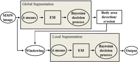
The multi-level segmentation comprises global and local segmentations. The global segmentation separates a person’s body area from the background. The local segmentation concerns only the inside of the body area in order to separate the object from the body. Figure 2 shows the block diagram of the multi-level segmentation.
(a) (b)
(c)
Figure 2. Block diagram of the multi-level segmentation.
Figure 3. Shape features of a gun.
This multi-level segmentation adopts k-means clustering for the GMM parameter initialization. The k-means algorithm is an unsupervised learning method to compose a number of clusters without any prior information [18]. The initial centroids of the clusters are set either by the split from a centroid or the randomly selected. In the experiments, the initialization is chosen when better result is provided. Three parameters (mean, variance, and weight) of the GMM distribution are initiated by thek-means algorithm. The EM method is an iterative solution for the maximum likelihood estimation of the GMM parameters [19]. The first Bayesian decision rule is followed by body area detection, which fills up any segmented are inside the body. The morphological erosion process estimates the accurate contour of the body area. The second level EM followed by the Bayesian decision rule segments the concealed object in the body area. More detailed procedures of the multi-level segmentation are presented in [9, 10]
4. SHAPE FEATURE ANALYSIS OF CONCEALED OBJECTS
Several shape features are employed to identify hidden objects. They are area (A), perimeter (T), major axis (w), and minor axis (h) of the basic rectangle, rectangularity (r), compactness (c), and eccentricity (e). Area is obtained by the number of pixels belonging to the object. Perimeter is the number of pixels composing the object boundary. The major axis represents the distance between two extreme points on the boundary. The minor axis is the line perpendicular to the major axis.
Figure 3 shows the shape descriptors of the gun model. Area is the number of pixels marked by “×” and perimeter is marked by “”. The major and minor axes compose each side of the basic rectangle, which is the smallest rectangle that bounds the object. Rectangularity is defined as
r = A
AR (1)
where AR is the area of the basic rectangle. Rectangularity shows how rectangular an object is. For example, it is one when the object is a rectangle. Circularity representing the compactness of the object is defined as
c= 4πA
T2 . (2)
It becomes one if the object is a circle. The following equation defines the eccentricity:
e=
1−
h w
2
, (3)
which is zero for a circle and between zero and one for ellipses.
5. EXPERIMENTAL RESULTS
(a)
10 20 30 40 50 10
20 30 40 50 60
10 20 30 40 50 10
20 30 40 50 60
10 20 30 40 50 10
20 30 40 50 60
(b)
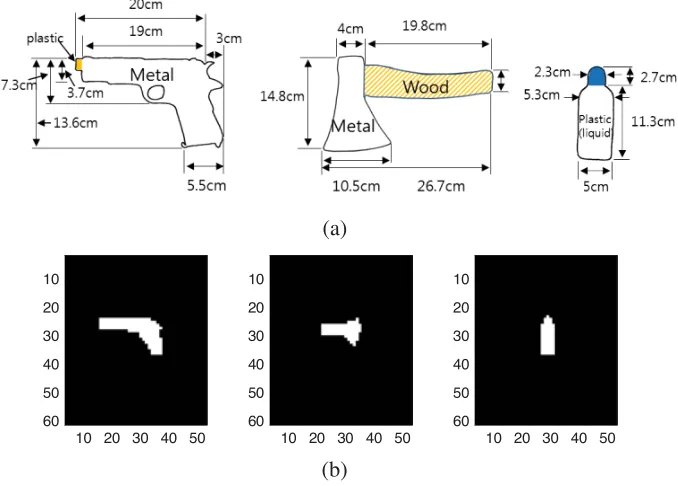
Figure 4. (a) Actual object size, (b) binary model.
(a) (b) (c) (d)
Figure 5. (a) A person hiding the object, demonstration of (b) gun, (c) hand ax, (d) plastic bottle containing liquid.
the objects. Figure 4(b) shows the binary models of Figure 4(a). The maximum sizes of the binary model for gun, hand ax, and plastic bottle are 22×13, 14×10, and 5×14 pixels, respectively. Thus, the pixel pitch in the binary object model corresponds to 1 cm. All of the passive MMW images are acquired when the person wears a sport training shirt to conceal the object as shown in Figure 5(a). Figures 5(b)–5(d) are presented only for demonstrating the objects attached to the person. The person faces the antenna 1.4 m away from the system. The scanning angle and the integrating time are set at 0.2◦ (≈0.0035 rad) and 60 msec, respectively. The images are acquired indoors during daytime without any illumination The room temperature is around 22◦C. The image size is 69×70 pixels. The metal, liquid in plastic, and wood (hand ax grip) are clearly visible as shown in Figures 6(a)–6(c).
10 20 30 40 50 60 10 20 30 40 50 60 70
10 20 30 40 50 60 10 20 30 40 50 60 70
10 20 30 40 50 60 10 20 30 40 50 60 70
(a) (b) (c)
Figure 6. Passive MMW images of a person hiding, (a) gun, (b) hand ax, (c) plastic bottle containing liquid.
10 20 30 40 50 60 10 20 30 40 50 60 70
10 20 30 40 50 60 10 20 30 40 50 60 70
(a) (b) (c) (d)
Probability density
0.015
0.01
0.005
0
0.5 0.55 0.6 0.65 0.7 Intensity Probability density 0.025 0.02 0.015 0.01 0.005 0
0.46 0.48 0.5 0.52 0.54 0.56 0.58 0.6 0.62
Intensity
Figure 7. Gun, (a) global segmentation, (b) GMM fitting of global segmentation, (c) local segmentation, (d) GMM fitting of local segmentation.
10 20 30 40 50 60 10 20 30 40 50 60 70
10 20 30 40 50 60 10 20 30 40 50 60 70
(a) (b) (c) (d)
Probability density
0.015
0.01
0.005
0
0.46 0.48 0.5 0.52 0.54 0.56 0.58 0.6 0.62 0.64 0.66
Intensity 0.45 0.5Intensity0.55 0.6
Probability density 0.035 0.02 0.015 0.01 0.005 0.04 0.03 0.025 0
Figure 8. Hand ax, (a) global segmentation, (b) GMM fitting of global segmentation, (c) local segmentation, (d) GMM fitting of local segmentation.
10 20 30 40 50 60 10 20 30 40 50 60 70
10 20 30 40 50 60 10 20 30 40 50 60 70
(a) (b) (c) (d)
Probability density 0.035 0.02 0.015 0.01 0.005 0.04 0.03 0.025 0 0.045
0.46 0.48 0.5 0.52 0.54 0.56 0.58 0.6 0.620.64 0.66
Intensity Probability density 0.025 0.02 0.015 0.01 0.005 0 0.03
0.46 0.48 0.5 0.52 0.54 0.56
Intensity
0.44
Figure 9. Plastic container with liquid, (a) global segmentation, (b) GMM fitting of global segmentation, (c) local segmentation, (d) GMM fitting of local segmentation.
liquid is not segmented during the global segmentation as shown in Figure 9(a).
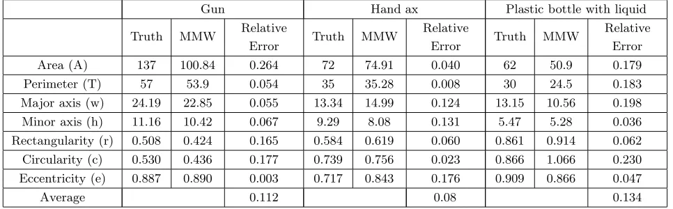
Minor axis (h) 11.16 10.42 0.067 9.29 8.08 0.131 5.47 5.28 0.036
Rectangularity (r) 0.508 0.424 0.165 0.584 0.619 0.060 0.861 0.914 0.062
Circularity (c) 0.530 0.436 0.177 0.739 0.756 0.023 0.866 1.066 0.230
Eccentricity (e) 0.887 0.890 0.003 0.717 0.843 0.176 0.909 0.866 0.047
Average 0.112 0.08 0.134
is slightly less than 1 cm (2×0.0035 rad∗1.4 m = 0.98 cm), area, perimeter and major and minor axes are compensated accordingly. The effective radiometric temperature highly depends on emissivity and reflectivity as well as the object and the ambient temperatures [1]. The emissivity of the liquid in the plastic bottle is closer to the body than other objects, which brings poor shape feature extraction following blurred object acquisition. The gunpoint has a narrow shape causing much error in estimating the area feature.
6. CONCLUSIONS
In this study, we have conducted shape feature analysis following the concealed object detection. Several shape features are extracted from the passive MMW images. They are compared with true values showing good accuracy around 87–92%. It has been seen that the accuracy depends on the radiation properties and the shape of the object. The former affects the effective radiometric temperature, and the latter is limited by the spatial resolution of the system. To recognize a number of objects automatically, pattern recognition technique [19] with learning process will be required, which remains for future study.
ACKNOWLEDGMENT
This work was supported by the Daegu University research grant.
REFERENCES
1. Yujiri, L., M. Shoucri, and P. Moffa, “Passive millimeter-wave imaging,” IEEE Microwave
Magazine, Vol. 4, No. 3, 39–50, 2003.
2. Appleby, R. and R. N. Anderton, “Millimeter-wave and submillimeter-wave imaging for security and surveillance,” Proc. IEEE, Vol. 95, No. 8, 1683–1690, 2007.
3. Chen, H.-M., S. Lee, R. M. Rao, M.-A. Slamani, and P. K. Varshney, “Imaging for concealed weapon detection: A tutorial overview of development in imaging sensors and processing,” IEEE
Signal Processing Magazine, Vol. 22, 52–61, 2005.
4. Kim, W.-G., N.-W. Moon, H.-K. Kim, and Y.-H. Kim, “Linear polarization sum imaging in passive millimeter-wave imaging system for target recognition,” Progress In Electromagnetics Research, Vol. 136, 175–193, 2013.
5. Demirci, S., H. Cetinkaya, E. Yigit, C. Ozdemir, and A. A. Vertiy “A study on millimeter-wave imaging of concealed objects: Application using back-projection algorithm,” Progress In
6. Sato, H., K. Sawaya, K. Mizuno, J. Uemura, M. Takeda, J. Takahashi, K. Yamada, K. Morichika, T. Hasegawa, H. Hirai, H. Nikura, T. Matsuzaki, S. Kato, and J. Nakada, “Passive millimeter-wave imaging for security and safety applications,”Proc. of SPIE, Vol. 7671, 76710V, 2010.
7. Shen, X., C. R. Dietlein, E. Grossman, Z. Popovic, and F. G. Meyer, “Detection and segmentation of concealed objects in Terahertz images,” IEEE Trans. on Image Processing, Vol. 17, No. 12, 2465–2475, 2008.
8. Haworth C. D., Y. De Saint-Pern, D. Clark, E. Trucco, and Y. R. Petillot, “Detection and tracking of multiple metallic objects in millimeter-wave images,”International Journal of Computer Vision, Vol. 71, 183–196, 2007.
9. Yeom, S., D. Lee, J.-Y. Son, M. Jung, Y. Jang, S. Jung, and S. Lee, “Real-time outdoor concealed-object detection with passive millimeter wave imaging,” Opt. Express, Vol. 19, No. 3, 2530–2536, 2011.
10. Yeom, S., D. Lee, and J.-Y. Son, “Multi-level segmentation of passive millimeter wave images for hidden object detection,” Optical Engineering, Vol. 51, 091613, 2012.
11. Li, L. C., J. Y. Yang, G. L. Cui, Z. M. Jiang, and X. Zheng, “Method of passive MMW image detection and identification for close target,” J. Infrared, Millimeter Terahertz Waves, Vol. 32, Nos. 102–115, 2011.
12. Jacobs, E. L. and O. Furxhi, “Target identification and navigation performance modeling of a passive millimeter wave imager,”Appl. Opt., Vol. 49, E94–E105, 2010.
13. Belongie S., J. Malik, and J. Puzicha “Shape matching and object recognition using shape contexts,”IEEE PAMI, Vol. 24, 509–521, 2002.
14. Yeom, S., D. Lee, Y. Jang, M. Lee, and S. Jung, “Real-time outdoor concealed-object detection with passive millimeter wave imaging,” Opt. Express, Vol. 20, No. 9, 9371–9381, 2012.
15. Gonzalez, R. C., Digital Image Processing 2/E, Prentice-Hall Inc., 2003.
16. Pitas, I., Digital Image Processing Algorithms and Applications, John Wiley & Sons, Inc., 2000. 17. Mingqiang, Y., K. Kidiyo1, and R. Joseph, Pattern Recognition Techniques, Technology and
Applications. Ch. 3: A Survey of Shape Feature Extraction Techniques, InTech, 2008.
18. Gersho, A. and R. M. Gray, Vector Quantization and Signal Compression, Kluwer Academic Publishers, Boston, MA, 1992.
19. Bishop, C. M.,Neural Networks for Pattern Recognition, Oxford, 1995.
20. Yeom, S., D. Lee, H. Lee, J. Son, and V. P. Gushin, “Vector clustering of passive millimeter wave images with linear polarization for concealed object detection,” Progress In Electromagnetics