A Compact Uniplanar Rat-Race Coupler with Arbitrary Power
Division Ratio and Harmonics Suppression
Qing He1, 2, *, Yinghong Wen1, 2, Song Chen1, 2, and Kai Wang3
Abstract—In this paper, a miniaturized planar rat-race coupler is proposed to achieve arbitrary power
division ratio and harmonic suppression performance simultaneously. It consists of six enhanced T-shaped line sections. The T-T-shaped lines can be equivalent to arbitrary electrical length lines rather than the conventional λ/4 lines. The explicit design formulas are derived and the characteristic impedances variations with the freedom variable are discussed. Simulated and experimental results show the harmonic suppression to be over −35 dB, while maintaining the conventional performance at the fundamental frequency. The circuit area of the prototype is only 30.8% of the conventional coupler.
1. INTRODUCTION
The rat-race hybrid is one of the fundamental components in microwave circuits [1, 2]. The perfect matching, ideal isolation, power-splitting capability and ease of implementation have led to its popularity. However, the conventional coupler has two main drawbacks which might be impractical. Initially, the traditional rat-race hybrid can work at its odd harmonics, which results in undesired interference introduced. With the growth of wireless communication systems, the rat-race couplers with harmonic suppression are in increasing demand. Nowadays there have been some kinds of harmonic suppression methods applied in the 3 dB rat-race hybrids [3–6]. It’s regret that the characteristic of arbitrary power division ratio isn’t considered in these designs.
On the other hand, the traditional coupler is composed of six quarter-wavelength transmission-line sections, which results in a large occupying area, especially at low frequencies [7, 8]. Accordingly, many attempts are continually being contributed to the miniaturization of rat-race couplers, as reported in [9–14].
In this paper, a compact planar unequal rat-race coupler with harmonic suppression is proposed by using the enhanced shaped transmission lines. Although there are some rat-race couplers with T-shaped transmission lines for harmonic suppression [15, 16], they can’t achieve arbitrary power division ratio, which limits their applications. For miniaturization, these T-shaped lines should substitute for the arbitrary electrical length transmission lines rather than the conventional λ/4 transmission lines as [15– 19]. In this paper, we take the model in [11] for example though this method can be applied in any other microstrip unequal design. The design equations of T-shaped lines are derived. For experimental verification, a model operating at 1 GHz with the third harmonic suppression is designed, simulated and measured. Due to its fully planar and no-via, the proposed coupler can be easily implemented by using the standard printed-circuit-board processes. Compared to the conventional unequal coupler, the measured results show compact size and well out-of-band harmonic rejection with the same performance at the operating frequency.
Received 16 January 2015, Accepted 4 March 2015, Scheduled 19 March 2015
* Corresponding author: Qing He (bomb [email protected]).
2. THEORY AND DESIGN EQUATIONS
Figure 1 illustrates the topology diagram of the proposed unequal rat-race coupler based on the arbitrary power division design in [11]. This structure can be divided into four sections S1–S4 by the four ports. For harmonic suppression, the enhanced T-shaped transmission line is used to replace the general transmission line in the rat-race coupler. A shunted stub is tapped to the center of the uniform section, which is shown in Figure 2. For the realizable impedances, the section S3 employs three series T-shaped lines as Figure 1. In Figure 2, Za, Zb, Zc, θa, θb and θc represent the characteristic impedances and the electrical lengths of the series, shunted sections and the uniform section, respectively. For arbitrary power division ratio G, the design equations of Zc and θc of every section have been derived in [11] as follows, where R0 is the port impedance.
⎧ ⎪ ⎪ ⎪ ⎪ ⎪ ⎪ ⎪ ⎪ ⎪ ⎨ ⎪ ⎪ ⎪ ⎪ ⎪ ⎪ ⎪ ⎪ ⎪ ⎩
ZcS1=ZcS3=
(G2+ 1)−(Gcosθ
cS2+ cos 2θcS1)2
sin 2θcS1 R0
ZcS2=ZcS4=
(G2+ 1)−(GcosθcS
2+ cos 2θcS1)2
GsinθcS2 R0
θcS3 =θcS1+ π
2
(GcosθcS2+ cos 2θcS1)2< G2+ 1
. (1)
For the identical performance at the operation frequency f0, the ABCD matrix of the enhanced
T-shaped lines should be equivalent to that of the general transmission lines, which is expressed as the Equation (2).
cosθc jZcsinθc
jsinθc/Zc cosθc
=
cosθa jZasinθa
jsinθa/Za cosθa
×
1 0
jtanθb/Zb 1
cosθa jZasinθa
jsinθa/Za cosθa
. (2)
After some straightforward manipulation, the characteristic impedance of T-shaped line can be calculated as follows:
Za= 1−cosθc
tanθasinθcZc, (3)
Zb= (1−cosθc) cos 2θ
atanθb
(cos 2θa−cosθc) sinθc Zc. (4)
And for harmonic suppression, the electrical length of the shunt stubθb can be determined by the suppression frequency fs (fs> f0) with the following formula [17]:
θb= π2ff0
s. (5)
Figure 1. The proposed unequal rat-race
coupler.
Za ,θa Za,θa
Zb,
θb
Z ,θc c
Figure 2. Substitution of a uniform section by
5 10 15 20 25 30 35 40 45 50 0
1 2 3 4 5 6
Z /Z
0 1 2 3 4 5 6
Z /Z
c
5 10 15 20 25 30 35 40 45 50
c
a b
θ =45°
θ =60°
θ =75°
θ =90°
c
c
c
c
θ =45°
θ =60°
θ =75°
θ =90°
c
c
c
c
a
θ (degree) θ a (degree)
(a) (b)
Figure 3. The variations ofZa/ZcandZb/Zcwithθafor differenceθcat the third harmonic suppression: (a)Za/Zc and (b)Zb/Zc.
The remaining parameter θa not only affects the performance of the T-shaped line, but also can be regarded as one degree of freedom in the circuit design. By optimizing the parameter θa, the characteristic impedances of T-shaped lines can be limited in the realizable range and the miniaturization can be achieved. For example, when the suppressed-frequency fs is chosen as 3f0, the normalized
characteristic impedancesZa/Zc andZb/Zcare illustrated as a function ofθafor differentθc in Figure 3. From Figure 3, it can be found that the curve of Za/Zc declines with the increase of θa and rises as
θc is increased, while the variation of Zb/Zc is the opposite. Since the function tanθb is increasing monotonically in the range ofθb, the characteristic impedance ofZb would be reduced as the rise of the suppressed-frequencyfs according to the Equations (4) and (5).
3. SIMULATION
In previous section, the design method of the proposed rat-race hybrid has been analyzed. For illustration, two different numerical cases are considered and simulated in this section. Both cases are simulated by using the circuit simulator ADS 2008. For simplification, the fundamental frequency is set at 1 GHz in these two examples.
3.1. The First Example
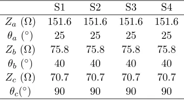
In the first example, the proposed rat-race coupler is expected to obtain equal power division outputs and reject the spurious signal at 2.25 GHz. The shunt stub of every section can be calculated to be
θb = 40◦ according to the Equation (5). For comparison, the Zc and θc of every section are designed
as the conventional rat-race hybrid. After optimizing, the θa of every section is set to be 25◦. Then all of the parameters can be derived and listed in Table 1. The simulation results are illustrated in the Figure 4.
Table 1. The design parameters of the first case.
S1 S2 S3 S4
Za (Ω) 151.6 151.6 151.6 151.6
θa (◦) 25 25 25 25
Zb (Ω) 75.8 75.8 75.8 75.8
θb (◦) 40 40 40 40
Zc (Ω) 70.7 70.7 70.7 70.7
From the Figure 4, it can be found that the proposed model has a similar performance with the conventional rat-race coupler at the operating frequency, while it has a wide rejection band around 2.25 GHz. The circuit circumference of this case is only 5λ/6, which is 55.5% of the conventional rat-race coupler.
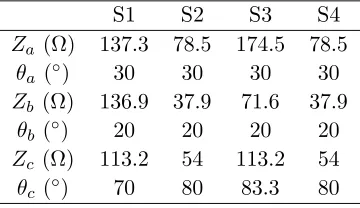
3.2. The Second Example
In the second example, the proposed rat-race coupler is designed to achieve 6.02 dB power division ratio. And the suppressed frequency is set at 4.5 GHz, which means θb = 20◦. For miniaturization and
S11
S21
S31
S41
S S S
0.6 0.8 1.0 1.2 1.4
Frequency (GHz)
phase S -S phase S -S
(c)
|S
| (dB)
|S
| (dB)
44 24
34
21 31
24 34
0.0 0.5 1.0 1.5 2.0 2.5 3.0 3.5 4.0
Frequency (GHz)
0.0 0.5 1.0 1.5 2.0 2.5 3.0 3.5 4.0
Frequency (GHz)
(a) (b)
-50 -40 -30 -20 -10 0
-50 -40 -30 -20 -10 0
-20 0 20 160 180 200
Phase difference (degree)
Figure 4. The simulated S-parameters of the first case: (a) the amplitude responses for in-phase,
(b) the amplitude responses for anti-phase, and (c) the phase responses.
Table 2. The design parameters of the second case.
S1 S2 S3 S4
Za (Ω) 137.3 78.5 174.5 78.5
θa (◦) 30 30 30 30
Zb (Ω) 136.9 37.9 71.6 37.9
θb (◦) 20 20 20 20
Zc (Ω) 113.2 54 113.2 54
power division ratio optimum, the θc of every section is designed as different electrical length rather than quarter wavelength. Then the T-shaped lines replace general electrical length transmission lines in this case. The design parameters are derived and listed in Table 2. The simulation results are showed in the Figure 5.
As it is expected, its power division ratio is 6.02 dB at 1 GHz with perfect matching and isolation responses. Meanwhile, the design has a wider rejection band than 1.5 GHz around 4.5 GHz. Compared with the first case, the phase difference response of this case is more flat. The circuit circumference of this case isλ, which is 2/3 of the conventional rat-race coupler.
0.0 0.5 1.0 1.5 2.0 2. 5 3.0 3. 5 4.0 4.5 5.0
|S
| (dB)
Frequency (GHz)
|S
| (dB)
0.50 0.75 1.00 1.25 1.50
Phase difference (degree)
Frequency (GHz)
0.0 0.5 1.0 1.5 2.0 2.5 3.0 3. 5 4.0 4.5 5.0 Frequency (GHz)
(c)
(a) (b)
S11
S21
S31
S41
S S S
44 24 34
-50 -40 -30 -20 -10 0
-50 -40 -30 -20 -10 0
-20 0 20 160 180 200
phase S -S phase S -S
21 31 24 34
Figure 5. The simulated S-parameters of the second case: (a) the amplitude responses for in-phase,
(b) the amplitude responses for anti-phase, and (c) the phase responses.
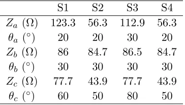
Table 3. The design parameters of this prototype.
S1 S2 S3 S4
Za (Ω) 123.3 56.3 112.9 56.3
θa (◦) 20 20 30 20
Zb (Ω) 86 84.7 86.5 84.7
θb (◦) 30 30 30 30
Zc (Ω) 77.7 43.9 77.7 43.9
4. MEASUREMENT
To validate our proposed method experimentally, a rat-race coupler operating at 1 GHz is designed to suppress third-order harmonic. The power division ratio is designated as 2, that is 6.02 dB. Based on the above method, the design parameters can be obtained and labelled in the Table 3. The prototype has been fabricated on a 0.762 mm-thick Rogers 4350B substrate, with relative permittivity ofεr= 3.48 and loss tangent of 0.003.
Figure 6 shows the comparison between the simulated and measuredS-parameters of the prototype
-40 -30 -20 -10 0
Magnitude (dB)
Simulation S Simulation S Simulation S Simulation S Measurement S Measurement S Measurement S Measurement S
-40 -30 -20 -10 0
Magnitude (dB) Simulation S Simulation S Simulation S Measurement S Measurement S Measurement S
0.6 0.8 1.0 1.2 1.4
-20 0 20 140 160 180 200
Phase differences (degree)
In-phase response measurement Anti-phase response measurement
In-phase response simulation Anti-phase response simulation
(c)
(a) (b)
1 3
Frequency (GHz)
1 3
Frequency (GHz)
2 2
11 21 31 41 11 21 31 41
44
34 24
44 34 24
Frequency (GHz)
Figure 6. The S-parameters of the prototype: (a) the amplitude responses for in-phase, (b) the
amplitude responses for anti-phase, and (c) the phase responses.
Table 4. The performance comparison between the proposed coupler and the existing designs.
coupler type relative size harmonic suppression power division conventional coupler [7] 100% no 1 : 1
[3] 45% fixed 1 : 1
[4] 31% arbitrary 1 : 1
[6] 21.5% fixed 1 : 1
[11] 57.6% no arbitrary
[13] 60% no 1 : 1
[14] 29% no 12 dB
the proposed 30.8% arbitrary arbitrary
using ADS software and HP 8720D vector network analyzer. It indicates that the actual centre frequency is 0.94 GHz and the third harmonic is 2.84 GHz, which means a slight frequency shift due to the fabrication tolerance. At the operating frequency, the measured return losses and isolation parameters are all better than−28 dB. The power division ratios are 5.82 dB with the insertion loss of|S21| −1.49 dB
and|S31|−7.31 dB, and the phase differences of in-phase and anti-phase are 1.4◦ and 181.3◦, respectively.
At the rejection frequency, the return losses are−0.48 dB, while harmonic output responses are rejected to more than −35 dB. It means that the prototype fulfills the third harmonic suppression with the excellent performance at the operating frequency. The photograph of this prototype is shown at Figure 7. The circuit circumference is only 5λ/6. The performance comparison between the proposed and the existing designs is shown in Table 4.
5. CONCLUSION
A compact unequal rat-race coupler with harmonic suppression has been proposed. It can be constructed using enhanced T-shaped lines which are equivalent to arbitrary electrical length transmission lines. The closed-form formulas have been derived usingABCD-matrix. For verification, two numerical cases are simulated in ADS 2008 software successfully. Then a prototype with power division ratio 6.02 dB is designed for the third harmonic suppression. It works well as a conventional unequal rat-race coupler at the operating frequency, while excellent rejecting the third-order harmonic component. The size of the prototype is only 30.8% of the conventional rat-race coupler without the folded lines.
ACKNOWLEDGMENT
This work was supported in part by National Natural Science Foundation of China (Nos. U1234205, 61172021 and 20120009110005) and the fund project of Railway Ministry (No. 2014X012-B).
REFERENCES
1. Liu, Q., Y. Liu, Y. Wu, S. Li, C. Yu, and M. Su, “Broadband substrate integrated coaxial line to CBCPW transition for rat-race couplers and dual-band couplers design,” Progress In Electromagnetics Research C, Vol. 35, 147–159, 2013.
2. He, Q., J. Shen, Q. Liu, J. Li, and L. Liang, “A simplified dual-band rat-race hybrid for arbitrary power division ratio with only single shunt stub,” Journal of Electromagnetic Waves and Applications, Vol. 27, No. 16, 2101–2109, 2013.
4. Mondal, P. and A. Chakrabarty, “Design of miniaturised branch-line and rat-race hybrid couplers with harmonics suppression,”IET Microw. Antennas Propag., Vol. 3, No. 1, 109–116, 2009. 5. Lai, C. H. and T. G. Ma, “Miniaturised rat-race coupler with second and third harmonic suppression
using synthesised transmission lines,”Electron. Lett., Vol. 49, No. 22, 1394–1396, 2013.
6. Kuo, J. T., J. S. Wu, and Y. C. Chiou, “Miniaturized rat race coupler with suppression of spurious passband,”IEEE Microw. Wirel. Compon. Lett., Vol. 17, No. 1, 46–48, 2007.
7. Tyrrell, W.-A., “Hybrid circuits for microwaves,” Proc. IRE, Vol. 35, No. 11, 1294–1306, 1947. 8. Reed, J. and G.-J. Wheeler, “A method of analysis of symmetrical four-port networks,”IRE Trans.
Microw. Theory Tech., Vol. 4, No. 4, 246–252, 1956.
9. Kuo, J.-T. and C.-H. Tsai, “Generalized synthesis of rat race ring coupler and its application to circuit miniaturization,” Progress In Electromagnetics Research, Vol. 108, 51–64, 2010.
10. Rathore, J., S. Aditya, and R. S. C. Dutta, “A general analysis and new designs for the hybrid-ring directional coupler,”Indian J. Technol., Vol. 31, 827–830, 1993.
11. He, Q., Y. A. Liu, S. L. Li, M. Su, and Y. L. Wu, “A novel 180 degrees rat-race hybrid with arbitrary power division for complex impedances,” Journal of Electromagnetic Waves and Applications, Vol. 27, No. 3, 318–329, 2013.
12. Lin, F., Q.-X. Chu, and S.-W. Wong, “Compact broadband microstrip rat-race couplers using microstrip/slotline phase inverters for arbitrary power-dividing ratios,”Journal of Electromagnetic Waves and Applications, Vol. 26, Nos. 17–18, 2358–2364, 2012.
13. Kim, D. I. and G. S. Yang, “Design of new hybrid-ring directional coupler using λ/8 or λ/6 sections,” IEEE Trans. Microw. Theory Tech., Vol. 39, No. 10, 1779–1783, 1991.
14. Ho, K. L. and P.-L. Chi, “Miniaturized and large-division-ratio ring coupler using novel transmission-line elements,”IEEE Microw. Wirel. Compon. Lett., Vol. 24, No. 1, 35–37, 2014. 15. Velidi, V. K., M. K. Mandal, and A. Bhattacharya, “Uniplanar harmonic suppressed compact
rat-race couplers,”Microw. Optical Techn. Lett., Vol. 50, No. 11, 2812–2814, 2008.
16. Xu, H.-X., G.-M. Wang, and K. Lu, “Microstrip rat-race couplers,” IEEE Microw. Magazine, Vol. 12, No. 4, 117–129, 2011.
17. Tu, W. H. and K. Chang, “Compact second harmonic-suppressed bandstop and bandpass filters using open stubs,”IEEE Trans. Microw. Theory Tech., Vol. 54, No. 6, 2497–2502, 2006.
18. Liu, G.-Q., L.-S. Wu, and W.-Y. Yin, “A compact microstrip rat-race coupler with modified lange and t-shaped arms,” Progress In Electromagnetics Research, Vol. 115, 509–523, 2011.
![Figure 1 illustrates the topology diagram of the proposed unequal rat-race coupler based on the arbitrarypower division design in [11]](https://thumb-us.123doks.com/thumbv2/123dok_us/7744698.1268877/2.612.169.460.221.322/figure-illustrates-topology-diagram-proposed-unequal-arbitrarypower-division.webp)