HIS-EBG Unit Cells for Pattern and Frequency Reconfigurable Dual
Band Array Antenna
Raimi Dewan1, *, Mohamad K. A. Rahim1, Mohamad R. Hamid1, Mohamed Himdi2, Huda A. Majid3, and Noor A. Samsuri1
Abstract—The incorporation of Electromagnetic Band Gap (EBG) unit cells, a type of metamaterials, with a dual band array antenna is proposed. By configuring the band gap of EBG cells accordingly, the pattern of the array antenna is successfully reconfigured at lower band of 2.4 GHz while maintaining the pattern at higher band of 5.8 GHz. Three pattern directions have been achieved: initial radiation pattern, 349-degree shift and 11-degree shift of the H-field. The array antenna is also frequency reconfigurable by suppressing the radiation pattern of the antenna in four different EBG cells configurations. In pattern shifting mode, the realized gain of the antenna is satisfactorily maintained and is comparable with the standalone of dual band array antenna with the range of gains from 5.08 dBi to 6.14 dBi and 7.83 dBi at 5.8 GHz.
1. INTRODUCTION
Metamaterial is applied in science and engineering and is an engineered artificial material which consists of composite structure to display the unique the characteristic of material not found in nature [1]. The unique behaviour of metamaterial is implemented in optical and electronics field [2]. In microwave engineering, metamaterial is a material artificially designed to exhibit unique characteristics at resonant frequencies [3].
EBG cells are High Impedance Surface (HIS) [4] metamaterial which forbid or suppress the propagation of Electromagnetic Wave (EMW) at its band gap. The band gap is the bandwidth (BW) of the EBG cells which suppresses the designated EMW frequencies while allowing other frequencies to pass through it. EBG cells can be applied as a filter to rejecting unwanted frequency range, reducing mutual coupling (MC) between the antenna elements, as a frequency selector, and in amplifiers and couplers application [5, 6].
Reconfigurable antenna is a type of antenna that is capable of changing its operating frequency, pattern, polarization, and beam to fulfil the dynamic requirement of Wireless Communication Services (WCS) [7]. In [8], reconfigurable pattern is achieved by implementing slotted structures and diodes at the radiating element of the antenna. However, the slotted structure at the radiating part degrades the antenna gain performance to−6.03 dBi and−4.88 dBi at ON and OFF states of the diode, respectively. In this paper, a frequency and pattern reconfigurable antenna with the use of EBG cells unit cells is proposed. By manipulating the state of EBG cells located at various optimized positions of the antenna, the antenna achieves 3 different modes of pattern reconfigurability. By suppressing the pattern at the selected frequency, the antenna has also achieved frequency reconfiguration. This is done without embedding any reconfigurable component to the antenna radiating parts, transmission line or feeding
Received 2 September 2018, Accepted 12 November 2018, Scheduled 3 December 2018 * Corresponding author: Raimi Dewan ([email protected]).
network as in the conventional design of pattern reconfigurable antenna. To the best of our knowledge, there is no analysis has been done by employing a minimal number of EBG unit cells to achieve both pattern and frequency reconfigurations in an array antenna design. Different cases of copper and diode as switches are studied. The gain at both frequencies is relatively high in consideration of the number of radiating elements used. With pattern shift at the lower band, the antenna pattern can be reconfigured to direct the receiver at significant distance at 2.4 GHz while maintaining the pattern at 5.8 GHz. The proposed antenna found potential applications in WiMAX, Wi-Fi and other Industrial, Scientific and Medical (ISM) applications. Apart from that, the use of pattern reconfigurability contributes to energy saving as the pattern can be directed to the intended receiver. Frequency reconfigurability of the antenna reduces the interference with other existing wireless communication services (WCS) by alternately operating at the selected frequency. This potentially maintains the quality of the WCS in a dynamic environment.
2. EBG UNIT CELL AND ARRAY ANTENNA DESIGN
The array antenna and EBG unit cells are designed on a inexpensive Flame Retardant (Fr4) substrate with substrate thickness, copper thickness and dielectric constant of 1.6 mm, 0.035 mm, and 4.39, respectively. Full wave simulation in Computer Simulation Technology (CST) software is used to simulate and optimize the proposed structure. A square-shaped EBG cell is a conventional shape of EBG cell structure of which the initial dimension can be approximated from Equations (1)–(4) [9– 12]. λris the wavelength of the operating frequency, with the dielectric constantεrof the material (Fr4) taken into account, and c is the speed of light in free space. The initial dimension of the conventional unit cell of EBG cells is halve of the λr. L and C are the inductive and capacitive characteristics of the EBG cells surfaces. μo and μr are the permeabilities of air and material, respectively, while g is the spacing gap between the unit cells. h and w are the thickness of the substrate and width of the EBG cells unit cell, respectively. EBG cell is a High Impedance Surface (HIS) which suppresses the propagation of Electromagnetic Wave (EMW) from passing through it with high resistance.
λr = C
fr
εr+1 2
(1)
λEBG = λr
2 (2)
L=μrμoh (3)
C=εo(εr+ 1)
w+g π
ln
cos πg 2(w+g)
(4)
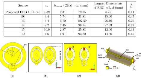
Table 1. The size comparison of EBG unit cells.
Source εr flowest (GHz) λr (mm) Largest Dimensions of EBG cell,d(mm)
d λr
Proposed EBG Unit cell 4.39 2.31 79.05 8.75 0.11
[9] 4.4 5.74 31.81 15.00 0.47
[13] 4.4 0.70 127.59 26.10 0.20
[14] 2.2 2.45 96.74 27.83 0.29
[15] 16.0 2.87 35.83 12.00 0.33
[10] 4.6 1.91 93.80 14.50 0.15
(a) (b) (c) (d)
Figure 1. (a) An EBG unit cell, (b) front view and (c) back side view of two EBG unit cells on single layer substrate. (c) 3-Dimensional (3D) diagram of suspended transmission line method which is used to analyze the band gap, S21 of EBG unit cells. Dimensions: ra= 2.5 mm, rb= 3.0 mm, rc= 4.0 mm and rd= 1.25 mm.
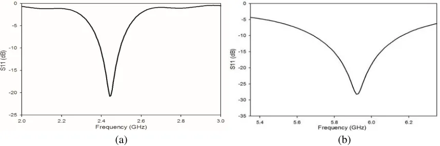
(a) (b)
Figure 2. (a) The simulated band gap, S21 performance comparison between 1 and 2 EBG cells. The simulated (b) band gap of 2-unit cells.
3. DUAL BAND ARRAY ANTENNA DESIGN WITHOUT EBG CELLS
(a) (b) (c) (d)
Figure 3. (a) The front, (b) back and (c) 3-dimensional exploded view of a single band antenna which operates at either 2.4 GHz or 5.8 GHz. Each of the single band antenna is optimized to construct the entire (d) array antenna with transmission feeding network. Dimensions of 2.4 GHz single band antenna:
Lf = 18.27 mm, Lp = 28.90 mm, Ls = W s = 70.00 mm, W p = 20.00 mm, and Y1 = 10.50 mm. Dimensions of 5.8 GHz single band antenna: Lf = 18.27 mm, Lp = 11.25 mm, Ls=W s = 70.00 mm,
W p= 15.00 mm, and Y1 = 2.88 mm.
(a) (b)
Figure 4. The simulated reflection coefficient, S11 of the dual band array antenna at (a) lower band of 2.4 GHz and (b) upper band of 5.8 GHz.
show that the dual-band array antenna operates at 2.4 GHz and 5.8 GHz band respectively. The realized gains of the stand-alone antenna are 6.214 dBi and 8.461 dBi at 2.4 GHz and 5.8 GHz, respectively.
4. DUAL BAND ARRAY ANTENNA DESIGN WITH EBG CELLS (IDEAL)
(a)
(b)
(c)
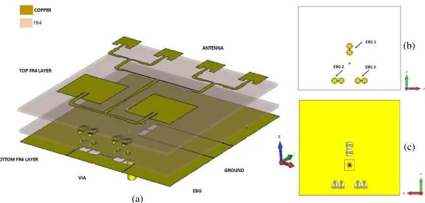
Figure 5. (a) The exploded 3-Dimensional view of the entire structure of dual band array antenna incorporated with EBG unit cells on dual Fr4 layers. The (b) front and (b) back view of the EBG unit cells which are located at bottom substrate layers.
Table 2. Various configuration EBG cells to facilitate reconfigurable in pattern of the dual band array antenna.
Conf. Frequency Reconf. (GHz)
EBG cells Conf. (0 = OFF)
(1 = ON) Changes In Pattern (θ) EBG 1 EBG 2 EBG 3
S0 S1 S0 S1 S0 S1 A
2.4 (lower band only)
1 1 1 1 1 1 No Changes
B 1 1 0 0 1 1 −θ
C 1 1 1 1 0 0 +θ
D 5.8 (Upper band Only) 0 0 0 0 0 0 No changes
side of the transmission feeding network which subsequently connects to the antenna radiating elements. Therefore, reconfigurable pattern is achieved by either turning ON or OFF the feeding network causing the antenna element to radiate and vice versa, respectively.
5. DUAL BAND ARRAY ANTENNA WITH EBG CELLS (ACTIVE)
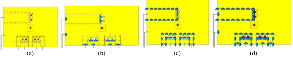
(a) (b) (c) (d)
Figure 6. The position of (a) diodes in the EBG cells, and the lumped elements of (b) inductor and (c) capacitor in the EBG cells biasing network at the bottom substrate layer. (d) Is the total components with biasing lines.
(a) (b) (c) (d)
Figure 7. Equivalent circuit of diode in (a) On and (b) Off state for the diode for below 4 GHz. Equivalent circuit of diode in (b) On and (c) Off state for the diode for above 4 GHz.
well as the overall biasing network. Figs. 7(a) and 7(b) show the diode equivalent circuit for OFF and ON conditions at two operating characteristics which are below 4 GHz and above 4 GHz. Diode acts as shorting element in ON states and as insulating element with high resistance at OFF states.
6. RESULT AND DISCUSSION
Figures 8(a) and 8(b) show the reflection coefficientS11results for all ideal and active cases that operate in conf. A, B and C at lower and upper bands, respectively. In these conf. A, B, and C, the antenna is operated at lower band only. Based on Fig. 8(a), the bestS11for both ideal and active cases is achieved when the antenna operates in conf. A where the antenna pattern is not shifted to any directions. In conf. B and C,S11of the antenna experiences degradation inS11performance. The alternate of ON and OFF of EBG 2 and EBG 3 creates some impedance mismatch which is actually used to realize pattern reconfiguration. However, despite the mismatch the antenna still satisfactorily yields high realized gain as tabulated in Table 3 which is comparable to the antenna in conf. A with goodS11 performance and the stand-alone dual-band array antenna which have realized gain of 6.214 dBi at 2.4 GHz. EBG cells suppress the propagation of wave at area of EBG 2 while allowing the propagation of wave at EBG 3 to shift pattern to one side, and vice versa, for the shift of the pattern to the opposite side. In contrast, based on Fig. 8(b), at 5.8 GHz, the propagation of wave is totally suppressed, thus the antenna operation at 5.8 GHz is successfully turned OFF with negative realized gains in Table 3.
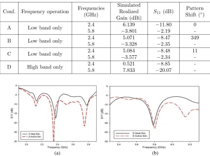
Figures 9(a) and 9(b) show the S11 results for ideal and active cases of the antenna operating in conf. D at lower and upper bands, respectively. Antenna operates at upper band only for conf. D. Based on Fig. 9(b), the antenna is successfully operated at 5.8 GHz for both ideal and active cases. In Fig. 9(b) and from Table 3, the antenna exhibitsS11 of−8.85 dB. TheS11 is a result of reflection coefficient at the main coaxial port to the antenna and not to the individual antenna radiating elements. Although based on S11, the operating frequency is not entirely turned OFF, the radiation pattern of the antenna at 2.4 GHz is significantly suppressed by 92% from 6.139 dBi to 0.521 dBi. In this condition, the antenna barely radiates at 2.4 GHz and is considered as turned OFF.
(a) (b)
Figure 8. Simulated reflection coefficient, S11 for ideal and active case at (a) lower band 2.4 GHz and (b) upper band 5.8 GHz. The antenna operates at lower band only in conf. A, B and C.
Table 3. Antenna performances: simulated realized gain and pattern shifting.
Conf. Frequency operation Frequencies (GHz)
Simulated Realized Gain (dBi)
S11 (dB) Pattern Shift (◦)
A Low band only 2.4
5.8
6.139
−3.801
−11.80
−2.19
0
-B Low band only 2.4
5.8
5.071
−3.328
−8.47
−2.35
349
-C Low band only 2.4
5.8
5.084
−3.577
−8.48
−2.34
11
-D High band only 2.4
5.8
0.521 7.833
−8.85
−20.07
-(a) (b)
Figure 9. Simulated reflection coefficient, S11 for ideal and active case at (a) lower band 2.4 GHz and (b) upper band 5.8 GHz. The antenna operates at upper band only in conf. D.
maintained as shown in Fig. 12.
(a) (b)
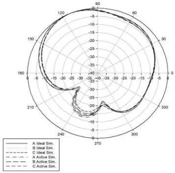
Figure 10. Simulated ideal case at (a) H-field and (b) E-field pattern for antenna operates in conf. A, B, and C.
(a) (b) (c)
Figure 11. Pattern comparison for ideal and active case at H-field for antenna operates in conf. (a) A, (b) B and (c) C.
(a) (b)
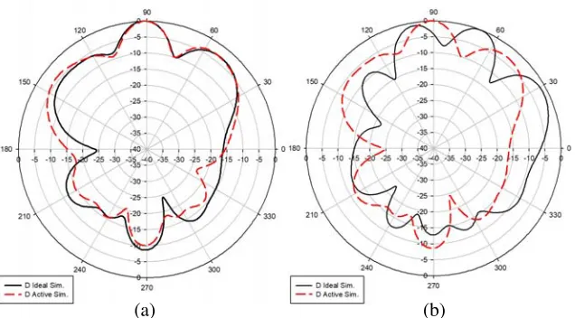
Figure 13. Pattern comparison for ideal and active case at (a) H-field and (b) E-field for antenna operates in conf. D.
the dual-band array antenna with frequency and pattern reconfiguration. The realized gain at 2.4 GHz is satisfactorily maintained and suppressed at 5.8 GHz when the antenna operates at lower band only. Pattern shift is observed with 11◦of variations. The realized gain at 5.8 GHz is satisfactorily maintained and effectively suppressed at 2.4 GHz when the antenna operates at upper band only.
7. CONCLUSION
A Frequency and Pattern Reconfigurable array antenna using EBG cells is proposed. A minimal number of six EBG unit cells is used to suppress the propagation of wave at the designated frequencies. With EBG cells, the pattern at 2.4 GHz can be manipulated in three directions while the pattern fixed at 5.8 GHz remains unchanged. The use of EBG unit cells only achieves pattern reconfigurability, but also realizes frequency reconfigurability with significant suppression of radiation pattern by EBG cells at either 2.4 GHz or 5.8 GHz operating frequency. Therefore, the EBG cells-incorporated array antenna is a pattern and frequency reconfigurable antenna. The antenna is suitable for various operating services such as WiMAX, and WiFi application and in dynamic wireless communication service where the operating frequency and pattern reconfiguration antenna is desired.
ACKNOWLEDGMENT
The authors thank the Ministry of Higher Education (MOHE) for supporting the research work; Research Management Centre (RMC), School of Postgraduate Studies (SPS), and Universiti Teknologi Malaysia (UTM) under grant no 12H09, 4F360, 4F883 and 12H08. The authors would also acknowledge all ARFMRG member especially the late Mr. Mohamed Abu Bakar.
REFERENCES
1. Muhamad, M., M. Abu, Z. Zakaria, and H. Hassan, “Novel artificial magnetic conductor for 5G application,”Indones. J. Electr. Eng. Comput. Sci., Vol. 5, No. 3, 636–642, 2017.
2. Fiddy, M. A. and R. Tsu, “Understanding metamaterials,”Waves in Random and Complex Media, Vol. 20, No. 2, 202–222, 2010.
4. Dewan, R., et al., “Artificial magnetic conductor for various antenna applications: An overview,”
Int. J. RF Microw. Comput. Eng., e21105-n/a, 2017.
5. Rajo-Iglesias, E., ´O. Quevedo-Teruel, and L. Incl´an-S´anchez, “Mutual coupling reduction in patch antenna arrays by using a planar EBG structure and a multilayer dielectric substrate,”IEEE Trans. Antennas Propag., Vol. 56, No. 6, 1648–1655, 2008.
6. Li, J., J. Mao, S. Ren, and H. Zhu, “Embedded planar EBG and shorting via arrays for ssn suppression in multilayer PCBs,”IEEE Antennas and Wireless Propagation Letters, Vol. 11. 1430– 1433, 2012.
7. Dewan, R., M. K. A. Rahim, M. R. Hamid, H. A. Majid, M. F. M. Yusoff, and M. E. Jalil, “Reconfigurable antenna using capacitive loading to Artificial Magnetic Conductor (AMC),”
Microw. Opt. Technol. Lett., Vol. 58, No. 10, 2422–2429, 2016.
8. Choi, J. and S. Lim, “Frequency and radiation pattern reconfigurable small metamaterial antenna using its extraordinary zeroth-order resonance,” Journal of Electromagnetic Waves and Applications, Vol. 24, Nos. 14–15, 2119–2127, 2010.
9. Alam, M. S., M. T. Islam, and N. Misran, “A novel compact split ring slotted electromagnetic bandgap structure for microstrip patch antenna performance enhancement,” Progress In Electromagnetics Research, Vol. 130, 389–409, 2012.
10. Islam, M. T. and M. S. Alam, “Compact EBG structure for alleviating mutual coupling between patch antenna array elements,” Progress In Electromagnetics Researc, Vol. 137, 425–438, 2013. 11. Majid, H. A., M. K. A. Rahim, M. R. Hamid, and O. Ayop, “Reconfigurable wideband to
narrowband antenna using tunable EBG structure,”Appl. Phys. A Mater. Sci. Process., Vol. 117, No. 2, 657–661, 2014.
12. Yang, F. and Y. Rahmat-Samii, Electromagnetic Band Gap Structures in Antenna Engineering, Cambridge University Press, Cambridge, 2008.
13. Zhang, J., G. Ci, Y. Cao, N. Wang, and H. Tian, “A wide band-gap slot fractal UC-EBG based on moore space-filling geometry for microwave application,”IEEE Antennas and Wireless Propagation Letters, Vol. 16, 33–37, 2017.
14. Ali, M., B. Abbasi, S. Member, S. S. Nikolaou, M. A. Antoniades, and M. Nikoli, “Compact EBG-backed planar monopole for BAN wearable applications,”IEEE Trans. Antennas Propag., Vol. 65, No. 2, 453–463, 2017.
15. Zhao, L., D. Yang, H. Tian, Y. Ji, and K. Xu, “A pole and AMC point matching method for the synthesis of HSF-UC-EBG structure with simultaneous AMC and EBG properties,” Progress In Electromagnetics Research, Vo1. 133, 137–157, 2013.
16. Dewan, R., M. K. A. Rahim, M. R. Hamid, M. F. M. Yusoff, H. A. Majid, and B. A. F. Esmail, “Dual band to wideband pentagon-shaped patch antenna with frequency reconfigurability using EBGs,”Int. J. Electr. Comput. Eng., Vol. 8, No. 4, 2557–2563, 2018.
17. Dewan, R., M. K. A. Rahim, M. Himdi, M. R. Hamid, F. Zubir, and N. A. Samsuri, “Frequency reconfigurability array antenna with electromagnetic band gap (EBG) cells,”Asia-Pacific Microw. Conf. Proceedings, APMC, 747–750, 2017.