Moving Target Indication Radar
Hitesh Gaba & Harsh Yadav
Electronics & Communication Department, Dronacharya College of Engineering, Gurgaon, India
Email: [email protected]
Abstract –
MTI measuring systems are engineered for several years, supported system ideas evolved within the early 1950s. Digital
techniques currently allow easier
implementation however do
not modify the fundamental concepts;
staggered repetition periods to eliminate blind speeds; and MTI cancellers with the speed response formed by feed forward and feedback techniques. Radar MTI may be specialized in terms of the
type of clutter and environment:
airborne MTI (AMTI), ground MTI (GMTI) or may be combined mode: stationary and moving target indication (MTI). The foremost common approach
takes advantage of
the propagation. Several of the
present systems square measure
terribly productive considering their
performance, measured in terms of MTI
improvement issue or sub
muddle visibility. In this paper the basic MTI concepts and definitions are presented.
I. Introduction
RADAR (Radio Detection and Ranging) is a system used mainly in defense applications which is used to locate the target, that is, to find its exact position in the range which it covers. The drawback of conventional pulse RADAR is that it can determine only the range, that is, the
distance of the target from RADAR antenna. It cannot determine whether the target is moving or not and in which direction it is moving. Thus in order to determine the motion of the target we use MTI (Moving Target Indication) RADAR. MTI RADAR has become a boon for detecting motion of the targets in the field of RADAR Engineering. MTI RADAR is defined as the RADAR in which the Doppler Effect can be employed to differentiate between stationary and moving targets, with the former suppressed and only the latter displayed. In this process, the permanent echoes as well as those from very slow moving objects (if desired) are not displayed on the PPI (plan position indicator), and the radar controller can pay attention to the real aircraft. Along with the detection of moving targets it also eliminates the effect of stationary objects or stationary clutters. This can be achieved by using the Delay line canceller.
II. Evolution of radar
to work as a transmitter while for other
time it used to function as a receiver. The transmitting and receiving functions were time multiplexed. The received echo was demodulated, amplified and compared with the threshold level. But the disadvantage was that the Doppler frequency shift due to motion of the target was not detected. Thus such RADAR could not detect moving target. It was used only to detect stationary targets. After World War-I when aircrafts were used in war for the first time there was a need to detect moving targets in which the conventional RADAR failed. Also as the aviation industry progressed there was also a need to control the motion of aircrafts to prevent fatal accidents. Thus a special RADAR system to detect moving targets was developed called as MTI (Moving Target Indication) RADAR was developed. Another type of RADAR used to detect moving targets was Pulse Doppler
RADAR. Both the RADAR systems used the concept of Doppler frequency shift or Doppler Effect to detect the moving targets. History was made when Croydon airport of London was the first airport to use ATC (Air Traffic Control) system in the year 1921. It used the RADARS used to detect moving targets.
III. Doppler frequency shift
Doppler shift is an apparent change in frequency (or wavelength) due to the relative motion of two objects. Either one or both of the objects may be moving with respect to the ground. Radar systems exploit the Doppler shift to provide an indication of relative speed. When the two objects are approaching each other (closing), the Doppler shift causes a shortening of wavelength - or increase in frequency.
When the two objects are receding from each other (opening), the Doppler shift causes a lengthening of wavelength - or decrease in frequency. In case of an MTI RADAR, when the target is moving towards the RADAR, the frequency of the echo received from the target increases whereas if the target is moving away from the RADAR, the frequency of the echo received from the target decreases. Difference in the transmitted frequency and received frequency from the target is called as Doppler frequency and is denoted by fd.
IV. Difference between pulse Doppler radar and MTI radar
V. Working
Simple CW radar consists of a transmitter, receiver, indicator, and the necessary antennas. In principle, the CW radar may be converted into a pulse radar as shown in Fig. 1 by providing a power amplifier and a modulator to turn the amplifier on and off for the purpose of generating pulses. The chief difference between the pulse radar and the CW radar is that a small portion of the CW oscillator power that generates the transmitted pulses is diverted to the receiver to take the place of the local oscillator. It acts as the coherent reference needed to detect the Doppler frequency shift.
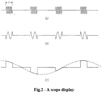
Moving targets may be distinguished from stationary targets by observing the video output on an A-scope (amplitude vs. range). A single sweep on an A-scope might appear as in Fig.2. This sweep slows several fixed targets and two moving targets indicated by the two arrows. O n the basis of a single sweep, moving targets cannot be distinguished from fixed targets. (It may be possible to distinguish extended ground targets from point targets by the string of the echo pulses. However, this is not a reliable means of discriminating moving from fixed targets since some fixed targets can look like point targets, e.g., a water tower. Also, some moving targets such as aircraft flying in formation can look like extended targets.) Successive A-scope sweeps (pulse-repetition intervals) are shown in Fig. Echoes from fixed targets remain constant throughout, but echoes from moving targets vary in amplitude from sweep to sweep at a rate corresponding to the Doppler frequency.
VI. MTI operation
the coherent reference is supplied by at
oscillator called the Coho, which stands for coherent oscillator. The Coho is a stable oscillator whose frequency is the same as the intermediate frequency used in the receiver. In addition to providing the reference signals the output of the Coho is also mixed with the local-oscillator frequency. The local oscillator- must be a stable oscillator and is called stalo. The RF echo signal is heterodyned with the stalo signal to produce the IF frequency just as in the super heterodyne receiver. They serve in both the receiver and the transmitter mode. The characteristic feature of coherent MTI radar is that the transmitted signal must be coherent (in phase) with the reference signal in the receiver. This is accomplished in the radar system diagramed in Fig.3 by generating the transmitted signal from rile Coho reference signal. The function of the stalo is to provide the necessary frequency translation from the IF to the transmitted frequency. Although the phase of the stalo influences the phase of the transmitted signal, any stalo
phase shift is canceled on reception because the stalo that generates the transmitted signal also acts as the local oscillator in the receiver. The reference signal from the coho and the IF echo signal are both fed into a mixer called the phase detector. The phase detector differs from the normal amplitude detector since its output is proportional to the phase difference between the two input signals.
VII. Blind speed limitation
The response of the single-delay-line canceller will be zero whenever the argument ΠfdT in the amplitude factor of is 0, Π , 2Π, . .., etc., or when
Where r l = 0, 1, 2, . . . , and j, = pulse repetition frequency. The delay-line canceller not only eliminates the d-c component caused by clutter (n = 0), but unfortunately it also rejects any moving target whose Doppler frequency happens to be the same as the prf or a multiple there of. Those relative target velocities which result in zero MTI response are called blind speeds are given by v = nλ/2T=nλfp/2
n = l , 2 , 3, ...
where vn, is the nth blind speed.
The blind speeds are one of the limitations of pulse MTI radar which do not occur with CW radar.
constraints other than blind speeds
which determine the wavelength and the pulse repetition frequency. Therefore blind speeds might not be easy to avoid. Low radar frequencies have the disadvantage that antenna beam widths, for a given-size antenna, are wider than at the higher frequencies and would not be satisfactory in applications where angular accuracy or angular resolution is important. The pulse repetition frequency cannot always be varied over wide limits since it is primarily determined by the unambiguous range requirement.
VIII. Staggered Pulse Repetitive Frequency
The use of more than one pulse repetition frequency offers additional flexibility in the design of MTI Doppler filters. It not only reduces the effect of the blind speeds, but it also allows a sharper low-frequency cutoff in the frequency response than might be obtained with a cascade of single-delay-line cancellers with sin nf,T response. The blind speeds of two independent radars operating at the same frequency will be different if their pulse repetition frequencies are different. Therefore, if one radar were “blind “to moving targets, it would be unlikely that the other radar would be “blind" also. Instead of using two separate radars, the same result can be obtained with one radar which time-shares its pulse repetition frequency between two or more different values (multiple prf's). The pulse repetition frequency might be switched every other scan or every time the antenna is scanned a half beam width, or the period might be alternated on every other pulse. When the switching is pulse to pulse, it is known as a staggered prf. An example of the
composite (average) response of an MTI radar operating with two separate pulse repetition frequencies on a time-shared basis is shown in Fig. 7. Repetition frequencies are in the ratio of 5 : 4. Note that the first blind speed of the composite response is increased several times over what it would be for radar operating on only a single pulse repetition frequency. Zero response occurs only when the blind speeds of each prf coincide.
XI. Conclusion
Here we have presented a special application of radar i.e. MTI radar which is far more superior to ordinary radar. The basic principle involved and its operation has been elaborated along with its limitations. MTI radar can be used for various air borne as well as well as ground based applications and shows a lot of promise in the near future.
References
[1] Livingstone, C. E., et al. "An airborne synthetic aperture radar (SAR) experiment to support RADARSAT-2 ground moving target indication (GMTI)."
Canadian Journal of Remote
Sensing 28.6 (2002): 794-813.
[2] Skolnik, Merrill I. "Introduction to radar." Radar Handbook (1962): 2.
[3] Soumekh, Mehrdad. "Synthetic aperture radar signal processing." A Wiley-Interscience publication, United States of America (1999).