Copyright to IJAREEIE DOI:10.15662/IJAREEIE.2016.0512057
9150
Efficient Power Quality for Wind Generation
based on BESS with Different Loading Conditions
in Integrity Networks
Mr DASARI A V N K Siva Prasad1, Mr M.Venkateswarlu21PG Scholar (Power Electronics), Department of EEE, Dr. Samuel George Institute of Engineering & Technology, Markapur 3Head of the Department-Associate Professor, Department of EEE, Dr. Samuel George Institute of Engineering & Technology, Markapur
1[email protected], 2[email protected]
Abstract— The power arising out of the wind turbine when connected to a grid system concerning the power quality measurements,
are: active power, reactive power, voltage sag, voltage swell, flicker, harmonics, and electrical behaviour of switching operation. These are measured according to national/international guidelines. To mitigate the power quality problems we are going to incorporate the BESS with a Static Compensator (STATCOM). So it is proposed to use Flexible AC Transmission System (FACTS) devices for the mitigation of power quality problems. The battery energy storage used to maintain constant real power from varying wind power. The generated power can be stored in the batteries at low power demand hours. The combination of battery storage with wind energy generation system will synthesize the output waveform by absorbing or injecting reactive power and enable the real power flow required by the load. The amount of energy consumed or given to the grid can be view through a Scope connected in the circuit. In each and every case we are calculating the Total Harmonic Distortion. The FACTS Device (STATCOM) control scheme with BESS for the grid connected wind energy generation system to improve the power quality is simulated using MATLAB/SIMULINK.
Keywords
—
Wind power, Distribution Network, Induction Generator, STATCOM, BESS, Reactive Power, Harmonics, and Power Quality.I. INTRODUCTION
Centralized power generation systems are facing the twin constraints of shortage of fossil fuel and the need to reduce emissions. Long transmission lines are one of the main causes for electrical power losses. Therefore, emphasis has increased on distributed generation (DG) networks with integration of renewable energy systems into the grid, which lead to energy efficiency and reduction in emissions. With the increase of the renewable energy penetration to the grid, power quality (PQ) of the medium to low voltage power transmission system is becoming a major area of interest. Most of the integration of renewable energy systems to the grid takes place with the aid of power electronics converters [1]. The main purpose of the power electronic converters is to integrate the DG to the grid in compliance with power quality standards. However, high frequency switching of inverters can inject additional harmonics to the systems, creating major PQ problems if not implemented properly. Custom Power Devices (CPD) like STATCOM (Shunt Active Power Filter), DVR (Series Active Power Filter) and UPQC (Combination of series and shunt Active Power Filter) are the latest development of interfacing devices between distribution supply (grid) and consumer appliances to overcome voltage/current disturbances and improve the power quality by compensating the reactive and harmonic power generated or absorbed by the load [2, 3].
Copyright to IJAREEIE DOI:10.15662/IJAREEIE.2016.0512057
9151
The proposed system with battery storage has the following objectives:• Unity power factor and power quality at point of common coupling bus. • Real and reactive power support only from wind generator and batteries to load.
• Self operation in case of grid failure. The utility companies can view the current, voltage and power of each system simultaneously by using the online smart metes. The utility can measure power generation of each system simultaneously. The most used unit to compensate for reactive power in the power systems are either synchronous condensers or shunt capacitors, the latter either with mechanical switches or with thyristor switch, as in Static VAR Compensator (SVC). The disadvantage of using shunt Capacitor is that the reactive power supplied is proportional to the square of the voltage. Consequently, the reactive power supplied from the capacitors decreases rapidly when the voltage decreases [3] .To overcomes the above disadvantages; STATCOM is best suited for reactive power compensation and harmonic reduction. It is based on a controllable voltage source converter (VSC). From reference [14] it is seen that there is no constant reactive power by using STATCOM, so in this paper we demonstrated a method by which the Power Quality issues are mitigated by connecting the Static Compensator with BESS at the point of common Coupling. The battery energy storage is integrated to sustain the real power source under fluctuating wind power. The STATCOM control scheme for the grid connected wind energy generation system for power quality improvement is simulated using MATLAB/SIMULINK.
Fig.1 Scheme of wind generator with battery storage [6].
II. STATICSYNCHRONOUSCOMPENSATOR(STATCOM)
The STATCOM is a shunt-connected reactive-power compensation device that is capable of generating and/ or absorbing reactive power and in which the output can be varied to control the specific parameters of an electric power system. It is in general a solid-state switching converter capable of generating or absorbing independently controllable real and reactive power at its output terminals when it is fed from an energy source or energy-storage device at its input terminals. Specifically, the STATCOM, which is a voltage-source converter which when fed from a given input of dc voltage, produces a set of 3-phase ac-output voltages, each in phase with and coupled to the corresponding ac system voltage through a relatively small reactance (which is provided by either an interface reactor or the leakage inductance of a coupling transformer). The dc voltage is provided by an energy-storage capacitor.
A STATCOM based control technology has been proposed for improving the power quality which can technically manages the power level associates with the commercial wind turbines. A STATCOM can improve power-system Performance like: 1. The dynamic voltage control in transmission and distribution systems,
2. The power-oscillation damping in power- transmission systems
3. The transient stability,
4. The voltage flicker control, and
Copyright to IJAREEIE DOI:10.15662/IJAREEIE.2016.0512057
9152
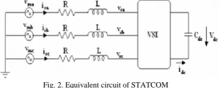
A STATCOM is analogous to an ideal synchronous machine, which generates a balanced set of three sinusoidal voltages at the fundamental frequency with controllable amplitude and phase angle. This ideal machine has no inertia, is practically instantaneous, does not significantly alter the existing system impedance, and can internally generate reactive (both Capacitive and inductive) power.Fig.2. shows the equivalent circuit of the STATCOM connected to the power system. The reactive power supplied by the STATCOM is either inductive or capacitive depending 1upon the relative magnitude of fundamental component of vs with respect to vm. If |v
m| > |vs|, the VSI draws reactive power from the ac bus whereas if |v m| < |vs|, it supplies reactive power to the ac system
Fig. 2. Equivalent circuit of STATCOM
III.POWERQUALITYISSUES
A. VOLTAGE VARIATION:
The voltage variation issue results from the wind velocity and generator torque. The voltage variation is directly related to real and reactive power variations. The voltage variation is commonly classified as under:
• Voltage Sag/Voltage Dips. • Voltage Swells.
• Short Interruptions.
• Long duration voltage variation.
The voltage flicker issue describes dynamic variations in the network caused by wind turbine or by varying loads. Thus the power fluctuation from wind turbine occurs during continuous operation. The amplitude of voltage fluctuation depends on grid strength, network impedance, and phase-angle and power factor of the wind turbines. It is defined as a fluctuation of voltage in a frequency 10–35 Hz.
B. HARMONICS:
The harmonic results due to the operation of power electronic converters. The harmonic voltage and current should be limited to the acceptable level at the point of wind turbine connection to the network. To ensure the harmonic voltage within limit, each source of harmonic current can allow only a limited contribution. The rapid switching gives a large reduction in lower order harmonic current com- pared to the line commutated converter, but the output current will have high frequency current and can be easily filter out. The harmonic distortion is assessed for variable speed turbine with a electronic power converter at the point of common connection [9]. The total harmonic voltage distortion of voltage is given as in (1)
V
THD=
√∑
𝑉𝑛2
𝑉1
100
40
ℎ=2
---(1)
Where Vn is the nth harmonic voltage and V1 is the fundamental frequency (50) Hz. The THD limit for
132 KV is <3 %.THD of current ITHD is given as in (2)
I
THD=
√∑
𝐼𝑛
𝐼1
100 ---(2)
Copyright to IJAREEIE DOI:10.15662/IJAREEIE.2016.0512057
9153
C. REACTIVE POWER:
Traditional wind turbine is equipped with induction generator. Induction Generator is preferred because they are inexpensive, rugged and requires little maintenance. Unfortunately induction generators require reactive power from the grid to operate. The interactions between wind turbine and power system network are important aspect of wind generation system. When wind turbine is equipped with an induction generator and fixed capacitor are used for reactive compensation then the risk of self-excitation may occur during off grid operation. Thus the sensitive equipment’s may be subjected to over/under voltage, over/under frequency operation and other disadvantage of safety aspect. The effective control of reactive power can improve the power quality and stabilize the grid. The suggested control technique is capable of controlling reactive power to zero value at point of common connection (PCC).
D. WIND TURBINE LOCATION IN POWER SYSTEM:
The way of connecting the wind generating system into the power system highly influences the power quality. Thus the operation and its influence on power system depend on the structure of the adjoining power network.
E. SELF EXCITATION OF WIND TURBINE GENERATING SYSTEM:
The self-excitation of wind turbine generating system (WTGS) with an asynchronous generator takes place after disconnection of wind turbine generating system (WTGS) with local load. The risk of self-excitation arises especially when WTGS is equipped with compensating capacitor. The capacitor connected to induction generator provides reactive power compensation. However the voltage and frequency are determined by the balancing of the system. The disadvantages of self-excitation are the safety aspect and balance between real and reactive power. The induction generators are widely used, due to the advantage of cost effectiveness, robustness, ruggedness, simplicity and requirement of no brush and commutators. However; induction generators require reactive power for magnetization. When the generated active power of an induction generator is varied due to wind, absorbed reactive power and terminal voltage of an induction generator can be significantly affected.
During the operation induction generator draws reactive power from the grid for its magnetization. Nonlinear load distorts the grid current waveform and also increase the harmonic component. Due to this, grid current is not in phase with the grid voltage and its wave shape is also different from sine wave which is shown in fig 4. Hence the power factor is not unity. Reactive power requirement of induction generator and load is supplied by the grid.
IV.REFERENCECURRENTGENERATIONFORSTATCOM
Reference current for the STATCOM is generated based on instantaneous reactive power theory [7] [10]. A STATCOM injects the compensation current which is a sum of reactive component current of IG, non-linear load and harmonic component current of non-linear load. P-Q theory gives a generalized definition of instantaneous reactive power, which is valid for sinusoidal or non-sinusoidal, balanced or unbalanced, three-phase power systems with or without zero sequence currents and/or voltages.
Copyright to IJAREEIE DOI:10.15662/IJAREEIE.2016.0512057
9154
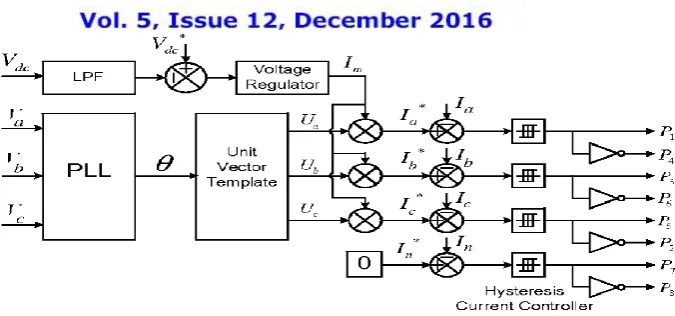
Fig. 3. Block diagram representation of grid-interfacing inverter control.
U
a= sin(𝜃)
---(3)
U
b=
sin( 𝜃 −
2𝜋
3
)
---(4)
U
c=
sin( 𝜃 +
2𝜋3
)
---(5)
The actual dc-link voltage (Vdc) is sensed and passed through a first-order low pass filter (LPF) to eliminate the presence of switching ripples on the dc-link voltage and in the generated reference current signals. The difference of this filtered dc-link voltage and reference dc-link voltage (V*
dc) is given to a discrete- PI regulator to maintain a constant dc-link voltage under varying generation and load conditions. The dc-link voltage error Vdcerr (n) at nth sampling instant is given as:
V
dcerr(n)= V
*dc(n)-V
dc(n)---(6)
The output of discrete-PI regulator at th sampling instant is expressed as
I
m(n)= I
m(n-1)+K
PVdc(V
dcerr(n)-V
dcerr(n-1))+K
IVdcV
dcerr(n)---(7)
Where KPVdc = 10 and KIVdc = 0.05 are proportional and integral gains of dc-voltage regulator. The instantaneous values of reference three phase grid currents are computed as
I
a*= I
m. U
a---(8)
I
b*= I
m. U
b---(9)
I
c*= I
m. U
c---(10)
Copyright to IJAREEIE DOI:10.15662/IJAREEIE.2016.0512057
9155
I
n*= 0 ---(11)
The reference grid currents ( I*a, I*b,I*c and I*n) are compared with actual grid currents ( Ia, Ib,Ic and In) to compute the current errors as
I
aerr= I
a*-I
a---(12)
I
berr= I
b*-I
b---(13)
I
cerr= I
c*-I
c---(14)
I
nerr= I
n*-I
n---(15)
These current errors are given to hysteresis current controller. The hysteresis controller then generates the switching pulses (P1 to P8) for the gate drives of grid-interfacing inverter. The average model of 4-leg inverter can be obtained by the following state space equations 𝑑𝐼𝐼𝑛𝑣𝑎 𝑑𝑡
=
(𝑉𝐼𝑛𝑣𝑎− 𝑉𝑎) 𝐿𝑠ℎ---(16)
𝑑𝐼𝐼𝑛𝑣𝑏 𝑑𝑡
=
(𝑉𝐼𝑛𝑣𝑏− 𝑉𝑏) 𝐿𝑠ℎ---(17)
𝑑𝐼𝐼𝑛𝑣𝑐 𝑑𝑡
=
(𝑉𝐼𝑛𝑣𝑐− 𝑉𝑐) 𝐿𝑠ℎ---(18)
𝑑𝐼𝐼𝑛𝑣𝑛 𝑑𝑡
=
(𝑉𝐼𝑛𝑣𝑛− 𝑉𝑛) 𝐿𝑠ℎ---(19)
𝑑𝑉𝑑𝑐 𝑑𝑡
=
𝐼𝐼𝑛𝑣𝑎𝑑+𝐼𝐼𝑛𝑣𝑏𝑑+𝐼𝐼𝑛𝑣𝑐𝑑+𝐼𝐼𝑛𝑣𝑛𝑑 𝐶𝑑𝑐---(20)
Where VInva, VInvb, VInvc and VInvn are the three-phase ac switching voltages generated on the output terminal of inverter. These inverter output voltages can be modeled in terms of instantaneous dc bus voltage and switching pulses of the inverter as
V
Inva=
(𝑃1−𝑃4) 2𝑉
dc---(21)
V
Inva=
(𝑃3−𝑃6) 2𝑉
d c---(22)
V
Inva=
(𝑃5−𝑃2) 2𝑉
dc---(23)
V
Inva=
(𝑃7−𝑃8) 2𝑉
dc---(24)
Copyright to IJAREEIE DOI:10.15662/IJAREEIE.2016.0512057
9156
I
Invad= I
Inva(
𝑃
1− 𝑃
4)
---(25)
I
Invbd= I
Invb(
𝑃
3− 𝑃
6)
---(26)
I
Invcd= I
Invc(
𝑃
5− 𝑃
2)
---(27)
I
Invad= I
Inva(
𝑃
7− 𝑃
8)
---(28)
The switching pattern of each IGBT inside inverter can be formulated on the basis of error between actual and reference current of inverter, which can be explained as: If IInva < (I*Inva-hb), then upper switch S1will be OFF (P1 =0) and lower switch S4 will be ON (P4=1) in the phase “a” leg of inverter. If IInva > (I*Inva-hb), then upper switch S1 will be ON (P1 =1) and lower switch S4 will be OFF (P4=0) in the phase “a” leg of inverter Where hb is the width of hysteresis band. On the same principle, the switching pulses for the other remaining three legs can be derived.
V. HYSTERESISCONTROLLER
With the hysteresis control, limit bands are set on either side of a signal representing the desired output waveform [6]. The inverter switches are operated as the generated signals within limits. The control circuit generates the sine reference signal wave of desired magnitude and frequency, and it is compared with the actual signal. As the signal exceeds a prescribed hysteresis band, the upper switch in the half bridge is turned OFF and the lower switch is turned ON. As the signal crosses the lower limit, the lower switch is turned OFF and the upper switch is turned ON. The actual signal wave is thus forced to track the sine reference wave within the hysteresis band limits.
Fig.4. Hysteresis current Modulation
VI.MATLABMODELEINGANDSIMULATIONRESULTS
Copyright to IJAREEIE DOI:10.15662/IJAREEIE.2016.0512057
9157
Copyright to IJAREEIE DOI:10.15662/IJAREEIE.2016.0512057
9158
Here simulation is carried out at different load conditions,1) Balanced Linear Load Condition, 2) Un-Balanced Linear Load Condition. 3) Balanced Non-Linear Load Condition 4) Un-Balanced Non-Linear Load Condition. 5) Variable Load Condition.
Case 1: Balanced Linear Load Condition
Fig.6. Simulation results for Balanced Linear Load (a) Source current. (b) Load current. (c) Compensator current. (d) Grid Voltage
Fig. 6 shows the source current, load current and compensator current & induction generator currents plots respectively. Here compensator is turned on at 0.1 seconds, for controlling active & reactive power.
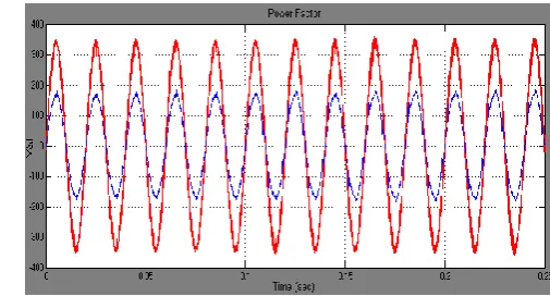
Fig.7 Simulation Results Power Factor For Balanced Linear Load
Fig. 7 shows the power factor it is clear from the figure after compensation power factor is unity.
Case 2: Un-Balanced Linear Load Condition
Fig. 8 Simulation results of Linear Unbalanced Load (a) Source Current (b) Load Current (c) Compensator Current (d) Wind Generator (Induction Generator) Current.
Fig. 8 shows the Simulation results of Linear Unbalanced Load, source current, load current, compensator current & induction generator currents respectively.
Fig.9 Simulation Results Power Factor For Linear Un-Balanced Load
Copyright to IJAREEIE DOI:10.15662/IJAREEIE.2016.0512057
9159
Case 3: Balanced Non-Linear Load Condition
Fig.10 Simulation results for Balanced Non Linear Load (a) Source current. (b) Load current. (c) Compensator Current. (d) Wind Generator (Induction Generator) Current.
Fig. 10 shows the source current, load current and
compensator current and induction generator currents plots respectively
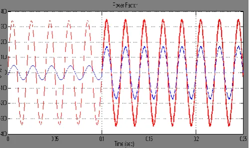
Fig.11 Simulation Results Power Factor For Balanced Non- Linear Load
Here compensator is turned on at 0.1 seconds, before we get some harmonics coming from non-linear load, then distorts our parameters and get sinusoidal when compensator is in on.
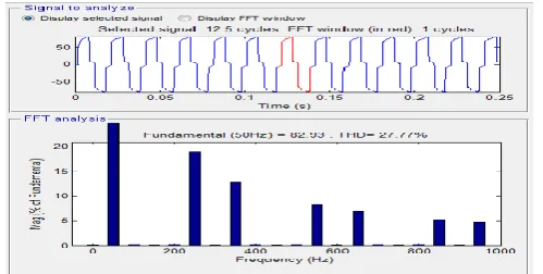
Fig. 12 FFT Analysis of Phase-A Source Current for Balanced Non-Linear Load
Fig.12 shows the FFT Analysis of Phase-A Source Current for Balanced Non-Linear Load, here we get 27.77%.
Fig. 13 FFT Analysis of Phase-A Source Current for Balanced Non-Linear Load
Fig.13 shows the FFT Analysis of Phase-A Source Current for Balanced Non-Linear Load, here we get 2.53%.
Copyright to IJAREEIE DOI:10.15662/IJAREEIE.2016.0512057
9160
Fig. 14 Simulation results of Non-Linear Unbalanced Load (a) Source Current (b) Load Current (c) Compensating Current (d) Wind Generator (Induction Generator) Current.
Fig.15 Simulation Results Power Factor For Un-Balanced Non- Linear Load
Fig.16 FFT Analysis of Phase-A Source Current for Un-Balanced Non- Linear Load
Case 5: Variable Load Condition
Fig. 17 FFT Analysis of Phase-A Source Current for Un-Balanced Non-Linear Load
Fig. 18 shows the Simulation results of Variable Load, source current, load current and compensator current and induction generator currents
Fig.19 Simulation Results Power Factor For Variable Load Condition
Fig. 19 shows the power factor it is clear from the figure after compensation power factor is unit
VII.CONCLUSION
Copyright to IJAREEIE DOI:10.15662/IJAREEIE.2016.0512057
9161
VIII REFERENCES[I] S. W. Mohod and M. V. Aware, “Micro wind power generator with battery energy storage for critical load”, in IEEE Systems Journal, Volume6, no.1, September 2012.
[2] G.Satyanarayana., K.N.V Prasad, G.Ranjith Kumar, K. Lakshmi Ganesh, "Improvement of power quality by using hybrid fuzzy controlled based IPQC at various load conditions," Energy Efficient Technologies for Sustainability (ICEETS), 2013 International Conference on , vol., no., pp.1243,1250, 10-12 April 2013..
[3] G. Satyanarayana, K.Lakshmi Ganesh , CH. Narendra Kumar, N. Srinivasa Rao “Realization of Hybrid Active Power Filter Applied to BLDC Motor Drive Using Dual Instantaneous Power Theory”, International Journal of Engineering Associates, Vol-1, Issue 3, p.p. 32-37, Feb, 2013..
[4] G. Satya Narayana, Ch. Narendra Kumar, Ch. Rambabu “ A Comparative Analysis of PI Controller and Fuzzy Logic Controller for Hybrid Active Power Filter Using Dual Instantaneous Power Theory” International Journal of Engineering Research & Development, Vol-4, Issue-6, p.p. 29-39, Oct, 2012.
[5]J. 0 .Q. Tande 'Applying Power Quality Characteristics of wind turbine for Assessing impact on Voltage Quality', Wind Energy, pp 52, 2002.
[6] L. H. Hansen, L. Helle, F. Blaabjerg, E. Ritchie, S. Munk-Nielsen, H. Binder, P. S0rensen and B. Bak - Jensen "Conceptual Survey of Generators and Power Electronics for Wind Turbines ", Ris0 National Laboratory, Roskilde, Denmark, December 200l.
[7] A.Arulampalam, M.Bames & NJenkins, Power quality and stability improvement of a wind farm using ST A TCOM, Proc. TEE Generation, Transmission & Distribution, Vol. 153, No.6, 2006, 701-710.
[8] A.Arulampalam, 1.B.Ekanayake & NJenkins, Application study of a ST A TCOM with energy storage, Proc. lEE Generation, Transmission & Distribution, Vol. 150, No. 3, 2003, 373-384.
[9] Fang Zheng Peng, Jih-Sheng Lai, 'Generalized Instantaneous Reactive Power Theory for Three-phase Power Systems', IEEE on instrumentation and measurement, vol. 45, no. I, Feb,1996.
[10] Fang Zheng Peng, , George W. Ott, Jr., and Donald J. Adams,' Harmonic and Reactive Power Compensation Based on the Generalized Instantaneous Reactive Power Theory for Three-Phase Four-Wire Systems' IEEE Trans on power electronics, vol. 13, no. 6, nov 1998.
[11] Leszek S. Czamecki:lnstantaneous Reactive Power p-q Theory and Power Properties of Three-Phase Systems' IEEE Trans on power delivery', vol. 21, no. I, [I 2] K. Derradji Belloum, and A. Moussi, 'A Fixed Band Hysteresis Current Controller for Voltage Source AC Chopper' World Academy of Science, Engineering and Technology 45 2008.
[13] 1. Dalessandro, U. Drofenik, S. D. Round and 1. W. Kolar, 'A Novel Hysteresis Current Control for Three-Phase Three-Level PWM Rectifiers', Swiss Federal Institute of Technology (ETH) Zurich, Power Electronic Systems Laboratory.
[14] S.sumathy and S. lenin Prakash “A Novel STATCOM control scheme for grid connected wind driven Induction Motor for power quality Improvement” International Journal, volume-3, issue-7.
[14] D. Dragomir, N. Golovanov, P. Postolache, C. Toader, 'The connection to the grid of wind turbines'.
IX BIOGRAPHY
Mr. DASARI A V N K Siva Prasad, he is pursuing M.Tech at Dr. Samuel George institute of engineering &technology, Markapur. Affiliated to JNTU K Kakinada University.