IJEDR1602295
International Journal of Engineering Development and Research (www.ijedr.org)1658
1PG Student,2Asst. Prof.1 Department of Mechanical Engineering, 1Babaria Institute of Technology, Vadodara,India
___________________________________________________________________________________________________
Abstract - Ultrasonic drilling is effective method compared to conventional drilling as in conventional process too much energy wasted to produce unwanted chips. It is a non thermal process so PTFE material not thermally damage with USM. The objective of this study is to check the feasibility of polytetrafluoroethelene for a ultrasonic machining. The effect of Pressure, Amplitude & Thickness of PTFE sheets on MRR, Taper & Overcut can be studied and determined. The effect of parameters on the process can be studied that can be useful for various analysis. The factors affecting Ultrasonic Machining performance are found from literature review & the effect of same is to be experimentally investigated. Full factorial Design for 3 input parameter at 3 level with 2 replication chosen for analysis. Thickness is found most significant parameter for MRR. The results of grey optimization shows that for both rough finishing as well semi-finishing hole, higher GRG achieved at medium thickness & amplitude and for maximum pressure.
IndexTerms - PTFE, USM, Ultrasonic Machining, MRR, Taper, Overcut, Pressure, Amplitude, Ultrasonic Drilling
________________________________________________________________________________________________________
I.INTRODUCTION :
Ultrasonic machining (USM) is the removal of material by the abrading action of grit – loaded liquid slurry circulating between the work-piece & tool vibrating perpendicular to the workface at a frequency above the audible range. In USM abrasive slurry freely flows between the work-piece & vibrating tool. The tool never contacts the work-piece and as a result the grinding pressure is rarely more, which makes this operation perfect for machining extremely hard and brittle materials, such as glass, sapphire, ruby, diamond, and ceramics.
The working process of an ultrasonic machine is performed when its tool interacts with the Work-piece or the medium to be treated. The tool is subjected to vibration in a specific direction, frequency and intensity. The vibration is produced by a transducer and is transmitted to the tool using a vibration system.
II.MECHANISM OF MATERIAL REMOVAL FOR USM:
As the tool vibrates abrasive particle indents the work material. During indentation, due to hertzian contact stresses cracks would develop just below the contact site and as the indentation goes on, cracks would propagate due to increase in hertzian stresses thus leading to brittle fracture of work material under each interaction between abrasive grit and work piece.
In ultrasonic machining, tool of desired shape vibrates at ultrasonic frequency (19-25 kHz) with amplitude of 15-50 Microns over work-piece. In Ultrasonic machining material removal is due to crack initiation, propagation and brittle fracture of material. USM is used for machining hard and brittle materials, which are poor conductors of electricity and thus cannot be processed by (ECM) or (EDM).
III. LITERATURE REVIEW :
Various researchers are working on laser cutting process to cut various materials. They are working on various parameters.
T.B.Thoe et. al. [1] highlighted that the Ultrasonic machining is of particular interest for the cutting of non-conductive, brittle work piece materials such as ceramics. Unlike other non-traditional process such as laser beam and electrical discharge machining, etc., ultrasonic machining does not thermally damage the work piece or appear to introduce significant levels of residual stress, which is important for the survival of brittle materials service. The fundamental principles of ultrasonic machining, the material removal mechanisms involved and the effect of operating parameters on material removal rate, tool wear rate and work piece accuracy were reviewed, with particular emphasis on the machining of engineering ceramics. The problems of producing complex 3-D shapes in ceramics were outlined.
IJEDR1602295
International Journal of Engineering Development and Research (www.ijedr.org)1659
Fig. 1.1 Principle of USM [21]Zarepour and Yeo [3] developed a model to predict material removal modes in ductile and brittle material when the brittle material is impacted by single sharp abrasive particle in micro ultrasonic machining process. They predicted the material removal modes for silicon <100> and fused quartz. They studied morphology of the crater formed and observed three modes of material removal namely pure ductile, partially ductile (transition mode) and pure brittle.
Basem M. A. Abdo et. al. [4] investigated that difficult-to-machine materials such as Ti-6Al-4V are very hard, tough, and possessed high impact resistance, their machinability is low and sometimes impossible with traditional machining processes. The results of this work identify that the cutting forces increase significantly with increase in coolant pressure, vibration amplitude, depth of cut and feed rate while decrease with increase in spindle speed.
M. Wiercigroch et al. [5] conducted an experiment and showed that an introduction of high-frequency axial vibration significantly enhances drilling rates compared to the traditional rotary type method. It has been found out that the material removal rate (MRR) as a function of static load has at least one maximum. It is postulated that the main mechanism of the MRR enhancement is associated with high amplitudes of forces generated by impacts. Novel procedures for calculating MRR are proposed, explaining an experimentally observed fall of MRR at higher static loads.
Kang et al. [6] investigated the material removal rate and surface quality of the alumina (Al2O3) which was ultrasonically machined using SiC abrasive under various machining conditions. They investigated that material removal rate increases as the static pressure and slurry concentration increases. They concluded higher material removal rate in case of rectangular sectional profile of the tool as compared to square sectional profile of the tool when tool of same cross-section area are used. They resulted an improved surface roughness of about 0.76 µm when machining was done by using abrasive of mesh number 600.
Chandra Nath and M. Rahman et al. [7] studied the effect of three important parameters: tool vibration frequency, tool vibration amplitude and work-piece cutting speed on ultrasonic vibration cutting (UVC). They concluded UVC method as a suitable technique to achieve high-quality finish surfaces for Inconel 718. They concluded that a minimum Ra value of 0.6 mm and 2.4 mm was achieved with the UVC method CT method respectively. They also concluded that value of TWCR should be kept as low as possible that is by increasing both the tool vibration frequency and amplitude, as well as by decreasing the work-piece cutting speed.
IJEDR1602295
International Journal of Engineering Development and Research (www.ijedr.org)1660
Jatinder Kumar et. al. [11] conducted experiments to assess the effect of three factors tool material, grit size of the abrasive slurry and power rating of ultrasonic machine on machining characteristics of titanium using full factorial approach for design and analysis of experiments. It has been concluded that titanium is fairly machinable with USM process. Moreover, the surface finish obtained is better than many of the other non-traditional processes. Surface roughness of the machined surface has been found to depend on grit size of the slurry used. Tool material and power rating have negligible effect on surface roughness. Optimum values for surface roughness were obtained with grit size 500 for alumina.Yasuhiro Kakinuma et al. [12] investigated Ultrafast Feed Drilling of Carbon Fiber-Reinforced Thermoplastics. Demand for through-hole drilling of CFRTPs is increasing. In this study, the machinability in drilling of CFRTPs under various conditions was experimentally analyzed in terms of the material properties, and a feasibility study of ultrafast feed drilling was conducted. The results showed that delamination at the outlet surface can be significantly suppressed during high rotational drilling when the feed rate is set to more than 3000 mm/min. By providing appropriate drilling conditions to prevent polymers in CFRTPs from softening, ultra-fast drilling of CFRTPs was successfully achieved under dry conditions.
V. Baghlani et al. [13] investigated Ultrasonic assisted deep drilling of Inconel 738LC super alloy. Super alloys have a poor machinability and are often drilled using (EDM) methods. However EDM is a time-consuming process and has low surface integrity. Ultrasonic Assisted Drilling (UAD) technology is a modern method of drilling such materials. The effect of ultrasonic vibration amplitude, spindle speed and number of steps to drill each hole on machining force and surface roughness were investigated. The results show that increasing material removal rate makes drilling more difficult and increases forces and surface roughness. An average thrust force of 417N and surface roughness of 1.610µm was obtained.
Komaraiah and Reddy [14] investigated the influence of work material properties such as fracture toughness and hardness on material removal rate in ultrasonic machining of hard and brittle materials. The work-piece materials machined in this investigation were glass, ferrite, porcelain, alumina and tungsten carbide. MRR was reported to decrease with an increase in work material hardness and fracture toughness in almost linear fashion under controlled experimental conditions.
H. Dam et.al. [15] presented that a general survey of the processes that govern the ultrasonic machining of ceramics. The results were based on the drilling of holes in seven different ceramics and the aspects considered were production rate, tool wear, precision and surface quality. For tough materials, a low production rate, a high tool wear, and a low surface roughness were observed. For brittle materials the relationships are reversed; high production rate, low tool wear and high surface roughness. However, it was found also that there were important qualitative differences in the machined surfaces. Tough materials generally give material removal based on plasticity, and there seems to be a greater tendency for dense and non-porous materials to produce surfaces with texture.
IV. EXPERIMENTAL PROCEDURE :
The detailed procedure followed for ultrasonic drilling described as under:
1. Measure the weight of all the PTFE sample of 0.5 mm, 1 mm and 1.5 mm thickness. 2. Securely tighten horn by placing grease at mating face of booster and horn to prevent coupling losses. Tighten the horn using spanner carefully.
3. Open compressor air valve to supply compressed air.
4. Set the amplitude of vibrations and pressure as per the parameters of design of experiment table.
5. Start Ultrasonic Machine. Feed the PTFE samples against vibrating horn. Also record machining time using stopwatch.
6. Unload work piece and stop the Ultrasonic Machine.
7. Measure the weight of PTFE sample and top and bottom diameter of drilled hole. 8. Note down the data in the observation table and marked on the sample.
9. Repeat process (4) to (8) for all the samples.
IJEDR1602295
International Journal of Engineering Development and Research (www.ijedr.org)1661
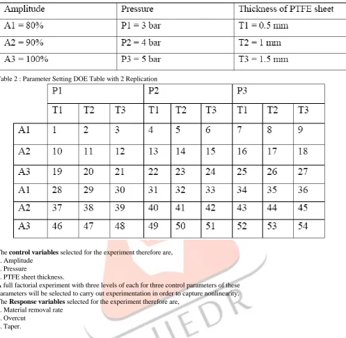
Table 2 : Parameter Setting DOE Table with 2 ReplicationThe control variables selected for the experiment therefore are, 1. Amplitude
2. Pressure
3. PTFE sheet thickness.
A full factorial experiment with three levels of each for three control parameters of these parameters will be selected to carry out experimentation in order to capture nonlinearity. The Response variables selected for the experiment therefore are,
1. Material removal rate 2. Overcut
3. Taper.
A full factorial design (FFD) only can help in estimating such interactions. Hence, FFD (three factors, each at three levels) was chosen for this study. A complete replicate of this design requires 27 experimental runs. Hence, a total of 54 trials, which includes two sets of 27 trials for full replication, are to be performed for drilling as indicated in Parameter Setting Table
OVERCUT (mm) = Actual diameter of hole –Diameter of hole
TAPER = (Top diameter of hole – Bottom diameter of hole) / Thickness MRR (gm/min) = Weight difference before and after drilling / Time
IJEDR1602295
International Journal of Engineering Development and Research (www.ijedr.org)1662
VI. OPTIMIZATION USING GREY RELATIONAL ANALYSIS :Grey analysis is a new technology - group of techniques for system analysis and modeling. It is also called grey logic / grey system theory. Grey analysis is useful in
situations with incomplete and uncertain information. Grey analysis is particularly applicable in instances with very limited data and in cases with little system knowledge or
understanding.
From the listing of grey relational grades in Table 5.6 for drilling, it is observed that for both these machining operations and for roughing as well semi-finishing the best rank is attributed to DOE serial 8 which relates to maximum pressure and mid value of amplitude & thickness. This is matching with the experimental findings and subsequent analysis showing that MRR is higher for lower thickness values and higher pressure and amplitude values. In case of semi-finishing the effective contribution of MRR to the grade is greater as compared to the combined effect of ROC and taper which leads to the same combination being selected as the best for semi-finishing. In case of finishing cut, however, due to the significant importance given to reduction in ROC and taper. the lowest combination of all variables as in DOE serial 8 is found to be optimum for both ultrasonic drilling.
IJEDR1602295
International Journal of Engineering Development and Research (www.ijedr.org)1663
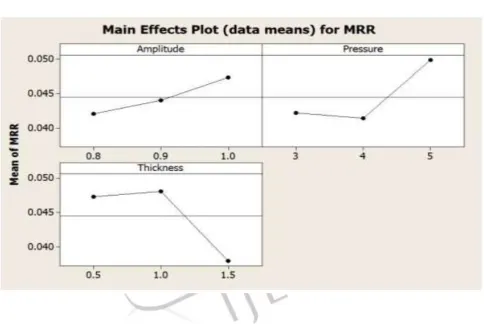
VII. CONCLUSION :1. The MRR is found to increase with increase in amplitude & pressure and decrease with increase in thickness of PTFE sheet for drilling.
2. The overcut is found to increase with increase in amplitude & decrease with increase in pressure and thickness.
3. The taper is also found to decrease with increase in thickness and in case of pressure initially taper is decreased for lower pressure but for higher pressure taper is increased which shows opposite result as compared to amplitude.
4. Based on ANOVA results, pressure and thickness are found to be most significantly affecting parameters for MRR and overcut and thickness & amplitude is found most significant factor for the taper.
5. The reason for abrupt change in MRR, taper & overcut is because of sometimes plastic deformation take place in addition to cutting, which affect the geometry of the hole.
6. The results of grey optimization shows that for both rough finishing as well semifinishing holes the best rank is attributed to medium thickness & amplitude and for
maximum pressure.
VIII. REFERENCES :
[1] T. B. Thoe, D. K. Aspinwall, M. L. H. Wise, “Review on Ultrasonic Machining”, International Journal of Machine Tools & Manufacture vol. 38, No.(1988) 4, pp, 239–255, 1988.
[2] X.Wang, M. Zhou, J. K. Gan and B. Ngoi, “Theoretical and Experimental Studies of Ultraprecision Machining of Brittle Materials with Ultrasonic Vibration”, International Journal Advanced Manufacturing Technology, vol. 20, no. 2, p. 99–102, 2012. http://link.springer.com/article/10.1007%2Fs001700200130
[3] H. Zarepour and S. H. Yeo, “Predictive modeling of material removal modes in micro ultrasonic machining,” International Journal of Machine Tools & Manufacture, vol. 62, p. 13–23, 2012.
[4] Basem M.A. Abdo, S.M. Darwish, A.M. EL-Tamimi, Al-Ahmari A.M, “Experimental Investigation of Cutting Forces in Ti-6Al-4V Alloys Using Rotary Ultrasonic Machining,” International Conference on Aeronautical, Robotics and Manufacturing Engineering (ARME'2015) June 15-16, Bangkok (Thailand), 2015.
[5] M.Wiercigrocha, J. Wojewodab, A.M. Krivtsovc, “Dynamics of ultrasonic percussive drilling of hard rocks”, Journal of Sound and Vibration 280 (2005) 739–757, 2005.
[6] I. S. Kang, J. S. Kim, Y. W. Seo and J. H. Kim, “An Experimental Study on the Ultrasonic Machining Characteristics of Engineering Ceramics”, Journal of Mechanical Science and Technology, vol. 20, no. 2, pp. 227-233, 2006.
IJEDR1602295
International Journal of Engineering Development and Research (www.ijedr.org)1664
[11] Jatinder Kumar, J.S. Khamba, S.K. Mohapatra; “An investigation into the machining characteristics of titanium using ultrasonic machining”, International Journal of Machining and Machinabiliy of Materials, Vol. 3, No. 1/2, 2008.[12] Yasuhiro Kakinumaa, Takuki Ishida, Ryo Koike, Heiner Klemme, Berend Denkena, Tojiro Aoyama, “Ultrafast Feed Drilling of Carbon Fiber-Reinforced Thermoplastics”, Procedia CIRP 35 ( 2015 ) 91 – 95, 2015.
[13] V. Baghlani, P. Mehbudi, J. Akbari, M. Sohrabi, “Ultrasonic assisted deep drilling of Inconel 738LC superalloy”, Procedia CIRP 6 ( 2013 ) 571 – 576, 2013.
[14] Komaraiah M. and Reddy, P.N., “A study on the influence of work piece properties in ultrasonic machining”, International Journal of Machine tools and Manufacture Vol. 33(1993), pp 495-505, 1993.
[15] Dam H, Quist P. And Schreiber M, “Productivity, surface quality and tolerance in ultrasonic machining of ceramic”, Journal of material processing technology, vol. 51 No.1-4 (1995), pp 358-368, 1995.
[16] Guzzo P L and Shinohara A.H., “A comparative study on ultrasonic machining of hard and brittle materials”, Journal of Brazilian Society of Mechanical Science and Engineering, Vol. 26, No. 1(2004), pp. 56-64,2004.
[17] H. Hocheng K .L. Kuo and J.T. Lin, “Machinability of Zirconia Ceramic in Ultrasonic Drilling”, Materials and Manufacturing Processes, Vol. 14, No. 5, pp. 713-724, 1999.
[18] Sumit Kumar Samal, B.Tech thesis, “Study of Parameters of Ultrasonic machining”, National Institute of Technology, Rourkela.
[19] https://en.wikipedia.org/wiki/Polytetrafluoroethylene [20] http://fluoropolymerproducts.com/ptfe_applications.htm [21] www.mechanicaldesignforum.com
[22] www.slideplayer.com [23] www.springerreference.com [24] nptel.ac.in
![Fig. 1.1 Principle of USM [21]](https://thumb-us.123doks.com/thumbv2/123dok_us/8304605.1378509/2.595.138.475.50.438/fig-principle-of-usm.webp)