Walking Rover Trafficability - Presenting a
Comprehensive Analysis and Prediction Tool
Brian Yeomans and Chakravathini M. Saaj
Surrey Space Centre, University of Surrey, Guildford, United Kingdom Email: [email protected], [email protected]
Abstract. Although walking rovers perform well in rocky terrain, their performance over sands and other deformable materials has not been well studied. A better understanding of walking rover terramechanics will be essential if they are to be actually deployed on a space mission. This paper presents a comprehensive walking rover terramechanics model incorporating slip and sinkage dependencies. In addition to quantifying the leg / soil forces, the superior trafficability potential of a walking rover in deformable terrain is demonstrated, and a control approach is described which can reduce the risk inherent in traversing soils with unknown physical parameters. This work enhances the state of the art of legged rover trafficability and highlights some potential benefits from deploying micro-legged rovers for future surface exploration missions. Keywords: walking rover, terrain, trafficability, terramechanics, control
1
State of the Art
All missions to date to other planetary bodies have employed wheeled rovers, probably because the wheel as a means of locomotion is quite energy efficient, wheeled vehicle technology is well known and extensively studied, the wheel itself is a mechanically simple device even if the full vehicle is very complex, and as a consequence there is extensive Space heritage.
Despite this sucessful track record, there are some challenges. A wheeled rover cannot climb very steep slopes or traverse extremely high relief regions. Also soft, sandy terrain presents a significant risk of complete mission failure; both Mars Exploration Rovers have been stuck at some time, Spirit probably permanently so - see Fig. 1. It is also very likely that the performance expectations of rovers deployed on future missions will increase; mission planners will be aware that many of the most interesting scientific sites are in hard to reach locations high up in the cliffs and gullies of Mars, and in the rugged and often permanently shadowed cratered areas of the Lunar polar regions. Accessing these sites will demand excellent rover trafficability over many types of terrain, and there must be some question whether wheeled vehicle technology can adequately meet the greater challenge.
Walking rovers may offer a highly effective alternative solution. Walking vehi-cle capability on steep, rocky terrain has been studied on a number of occasions,
Fig. 1.Spirit Rover showing front left wheel stuck in soft soil in location ‘Troy’(Source: NASA)
and impressive results have been achieved using reflexive behaviours to negotiate unstructured environments - for example, the “Big Dog” project [1]. Combining the long distance capabilities and energy efficiency of a wheeled rover with the agility of a walking rover has been explored in [2] which utilised the SCORPION eight legged vehicle as a scout adjunct to a wheeled rover.
Walking rovers are complex machines, and this could mean increased risk of failure; however designed-in redundancy can help. A six - legged rover not only permits speed, efficiency and climbing ability trade-offs through gait pat-tern variation, but also incorporates redundancy given that only four legs are required for a statically stable gait. Finally, whilst there is no history of suc-cessful walking rover operation in Space, the individual components from which they are assembled do have history, as was demonstrated in [3].
Although a walking rover’s superior agility may not be in doubt, performance over all types of terrain, and particularly the soft deformable areas which have proved such a hazard on Mars, has not been well studied. The work presented in this paper addresses this gap through the development of a detailed analytical model of leg / terrain interaction for a walking vehicle.
2
The LPTPT Tool
2.1 Introduction
The Legged Performance and Traction Prediction Tool (LPTPT) comprises a comprehensive model of the interaction between deformable terrain and the legs of a walking rover [4].
LPTPT uses the MATLAB computation engine for its caculations and can produce both numerical and graphical output as required. The model contains a database of reference vehicles and physical data on a range of planetary soil
types, both real and simulated; currently interactions between ten vehicle and twenty five soil types can be assessed. The model analyses the forces arising between the vehicle and soil, and predicts the trafficability performance. Leg loading, and the effect of gait modification can be varied. The model’s force predictions have been validated by experiment using a test rig comprising a manipulator arm moving a representative leg / foot assembly through simulated planetary soils.
2.2 LPTPT Model - Phase 1
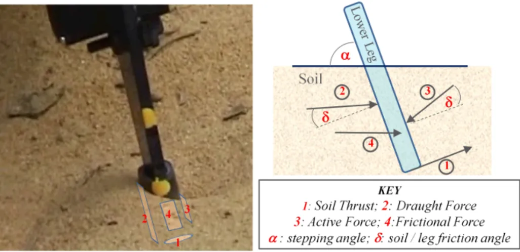
In Phase 1, LPTPT develops the basic force calculations. Fig. 2 identifies the forces arising on a leg stepping into soil.
Fig. 2.Leg / Soil Forces - location (left image) and direction (right image)
Four force types are described and quantified by LPTPT:
(i) Soil Thrust Ho, is the shear force acting on the foot / soil interface, providing forward traction.
The soil thrust at the foot / soil shear interface is based on the Mohr -Coulomb equation [5]. Themaximum shear stressτmax arising is:
τmax=Co+σtanφ, (1)
whereCoandφare the soil physical properties of cohesion and friction angle, andσ is the normal stress on the soil / foot interface. Soil Thrust can be derived from this equation by integrating the foot / soil shear stress values over the area of the contact patch.
(ii) Draught Force Fd, is the force between the soil and the leg / foot assembly cutting through the soil. This force provides additional traction for the ve-hicle unless the leg is stepping “forward” into the soil, in which case it will act to resist forward motion.
The draught force derivation in LPTPT is based on the application of tillage theory, the study of the mechanics of tool / soil interaction [6]. Terzaghi’s Universal Earthmoving Equation [7] as further developed by Reece [8] is used, and is expressed as follows:
F =γgz3Nγ+Coz2Nc+qz2Nq+Caz2Nca (2)
whereγ= unit weight of soil,gis acceleration due to gravity,zis the sinkage, Nc,q,a,ca are Terzaghi’s four dimensionless soil bearing capacity factors,qis the soil surcharge pressure, andCa is soil adhesion.
In order to compute the forces arising, the four soil bearing capacity fac-tors must be determined. Many methods have been devised to compute the factors, based on various interpretation’s of Terzaghi’s equation; McKyes [6] summarises the 2-D and 3-D models which have been used. LPTPT can compute these factors using several alternative models and selects the most appropriate approach based on the scenario, the principal criterion being the ratio of leg / foot width to soil sinkage.
The model predicts the angle of the failure plane of the soil in front of the moving leg / foot and then solves for the soil bearing capacity factors. An approach based on the study of narrow tools by Grisso et al [9] has been found to give good agreement with experimental results when applied to the narrow legs typically seen on walking vehicles.
(iii) Active Force Fa, which arises as soil falls back into the trench created by the leg as it moves through the soil. This force acts to assist the leg moving through the soil and so reduces traction.
The active force derivation is also based on Terzaghi’s analysis [7]. It is not described in detail here as at low to moderate levels of sinkage, active force has a negligible effect on the total forces arising.
(iv) Frictional Force Ff, the effect of friction between the soil and the foot / leg. Where the stepping angleαis high (α≈90o) , this force will provide further resistance to the leg moving back through the soil and so provides additional forward traction.
Frictional force is modelled in LPTPT following the same principles applied to determining the shear force at the foot / soil interface. At high values of stepping angle (α ≈ 90o), friction derives principally from the sides of the leg / foot assembly and depends on adhesion between the soil and leg assembly, the geometry of the leg / foot, and the sinkage depth.
(v) The Effect of Gravity.Unlike a wheeled vehicle, the leg attitude is decoupled from the attitude of the vehicle as a whole and therefore gravity does not directly affect the forces on the leg / soil interface; indirectly there is an effect however through alteration of the direction and amount of the loading on each leg due to the vehicle’s weight.
(vi) Changes in leg loading.The complex locomotion patterns of a legged vehicle will have a direct effect on the leg loading and thus on all the forces com-puted; the load per leg will be directly affected by the gait employed, and in the case of more complex gait patterns, the load per leg is likely to vary during the gait cycle. LPTPT allows “per leg” computations to be made and summed to derive overall Drawbar Pull (DP).
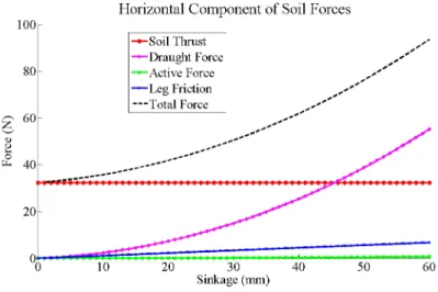
Fig. 3.Predicted Rover soil /leg interaction.
2.2.1 Results and Forces Summary. The results are illustrated in Fig. 3 which shows each of the forces arising, plotted against sinkage for an example 20kg hexapod walking in a low density granular soil. In this and subsequent plots, forces are resolved in the horizontal direction to derive the component which aids or hinders forward motion of the rover. The vehicle is modelled as adopting the slow but highly stable wave gait locomotion pattern under which only one leg is lifted at any time, the other five remaining in ground contact. The soil data is based on the in-house developed simulant Surrey Space Centre Simulant 2
(SSC-2), a fine grained garnet sand with a particle distribution profile similar to many lunar soils [10]. The figure highlights a number of significant features:
(i) The above analysis shows that each of the four forces modelled other than the Active Force act to increaseDP per leg as they increase.
(ii) All forces other than the Soil Thrust increase as sinkage increases; in the case of the Draught Force markedly so.
It follows that unlike a wheeled vehicle, where sinkage has a negative effect through increased compaction, bulldozing and other resistances, a degree of
sink-age, provided this is not so large as to overwhelm the vehicle, is of assistance to a legged vehicle as the force available to generate forward movement is increased.
2.3 LPTPT Model - Phase 2
LPTPT - 1 develops the basic force analysis and derives the maximum horizontal force available from all sources at the soil interface, given a known level of sinkage. Whilst this information enables a view to be formed of the potential of the rover / terrain combination to deliver thrust, it does not describe the impact of slip at the soil interface, and the consequent effect on sinkage and so on the forces generated.
LPTPT - 2 incorporates slip and sinkage modelling to enable it to directly show the effect on forces as these parameters vary. Additionally, sinkage and slip are vehicle operational parameters that can be measured or estimated, enabling terrain interaction predictions to be directly linked with vehicle performance.
2.3.1 Stress / Slip Relationship. Equation (1) gives the maximum avail-able shear stress; however the actual stress at the interface will depend on the amount of shear displacement at that interface, which is in turn dependent on the amount of slip.
The stress / shear relationship for sands can typically be characterised by one of two types of exponential function [11]. In both cases the shear stress tends to a constant residual level; in one case, characteristic of compacted sands [11], the curve shows a pronounced peak, whereas in the other case, characteristic of loose sands, there is no peak. Given that the degree of compaction may not be known, and to avoid overstating the forces available at the soil interface, LPTPT models the stress / shear relationship on the basis of a curve with no peak, using this relationship [12]:
τ=τmax1−e(−j/K), (3) where j is the shear displacement at the relevant point in the interface, andK is a further physical property of the soil, the shear deformation parameter; K can be considered as a measure of the shear displacement required to develop the maximum shear stress [11].
2.3.2 Slip Ratio. The slip ratio measures the extent to which the forward traction theoretically available at the leg / soil interface fails to be converted to actual forward motion. The slip ratio ican be defined as [11]:
i= 1− V
Vt, (4)
whereV is the actual forward speed andVtis the theoretical forward speed with perfect traction.
The force developed at the foot / soil interface is computed by substituting the Mohr - Coulomb relation from equation (1) for τmax and integrating the
resulting stress values over the contact patch area. The result will depend on the geometry of the foot, and therefore variations in foot design will directly affect the forces available. In the simple case of a flat, rectangular foot, of width b, lengthland areaA, the shear displacementjat a point under the foot is related to the slip ratio i and the distance from the front of the footxas j =ix[11]. In this simple case, the shear stress increases linearly across the length of the contact areal and the force can be derived analytically as:
F =b Z l 0 Co+ W bltanφ 1−e(−ix/K)dx (5) F = (ACo+W tanφ) 1−K il 1−e(−il/K) (6)
2.3.3 The impact of variations inK. Kis required to compute the above relation; however it may well not be known for the particular soil type and condi-tions applicable. Some commentators suggestK is constant; for example, Wong [11] quotes values forK of between 1cm and 2.5cm for sandy terrain. However, our test results gave values which were not constant and were much smaller than those quoted by Wong. LPTPT adopts a model proposed by Godbole and Alcock [13] to computeK derived from known laboratory reference values. This approach was found to be well supported by experimental results, and derivesK for the conditions applicable from values ofKmeasured in the laboratory using the following relationship:
(K1/K2) =
p
(A1/A2), (7)
where K1 is the value of K sought, K2 is the laboratory measured reference value,A1is the actual contact patch area for the given conditions andA2is the contact patch area applicable to the laboratory measurements.
2.3.4 Sinkage and Slip Sinkage. Static sinkage is modelled using the Bernstein-Bekker methodology relating pressurepand sinkagez[5]:
p= k c b +kφ zn (8)
wherekcis the cohesive modulus of soil deformation,kφthe frictional modulus of
soil deformation,nis an experimentally determined exponent (typically between 0.7 and 1.3), andbis the smaller dimension of the contact patch (the radius, in the case of a circular contact area).
With respect to slip sinkage, a number of methodologies have been developed, beginning with Bekker [5] who proposed a linear relationship between slip and slip sinkage:
wherezo= static sinkage, andzj= 2hi, whereiis the slip ratio andhequals the boundary layer of soil being sheared; equal to 1.2 times the height of grousers.
Reece in [14] proposed the following relationship, which also depends on grouser height:
zj= hgri
(1−i) (10)
One concern with this relation is that sinkage→ ∞at high slip levels.
Richter [15] proposes a non-linear relationship, whilst retaining the link with grouser height: zj= 2h i−i 2 2 (11) Lyasko [16] proposed the following relationship,which has been verified against experimental results: ztotal=Kss.zo (12) where Kss= 1 +i 1−0.5i (13) This relationship does not depend on grouser height, and does not→ ∞at high slip levels. Fig. 4 plots the respective slip and sinkage relationships, equating
Fig. 4.Slip - Sinkage profiles
grouser height and initial sinkage for comparison purposes. It can be seen that the three methods give similar results at lower levels of slip, diverging at higher levels. LPTPT adopts the Lyasko model, because:
(ii) Grousers may or may not be fitted, depending on the foot design, and this model does not depend on grouser height;
(iii) It is non linear, in accordance with observed results, and accords well with observed data.
LPTPT - 1 has been thoroughly tested using a lower leg segment moved through soil by a robotic arm manipulator. LPTPT - 2 testing is currently in progress, and employs a new test facility. The prior approach cannot be employed to test the slip dependency as the manipulator base and the soil are fixed relative to each other, and so only zero or 100% slip ratios can be achieved. A specially developed single leg testbed is used, comprising a suspended carriage to which the test leg is attached, which replicates the kinematics of the moving leg on the vehicle.
3
LPTPT Model Predictions
3.1 Wheeled Rover Comparison
WhilstDPis not the only criterion to comparatively evaluate rover performance, and typically a walking rover will operate at a lower level of energy efficiency that a comparable wheeled vehicle, there may be situations where maximising
DP is paramount,and so it is useful to evaluate the maximum DP available to a vehicle of comparable mass of each type. Ellery in [17] computed theDP
available toSojourner, the 11.5kg vehicle used in the Mars Pathfinder mission, as 6.88N net of bulldozing, compaction and other resistances. In contrast, LPTPT computesDP of a 11.5kg legged vehicle, walking with a wave gait in soil with the characteristics of that at the Viking lander 2 site, as 31.5N, a very substantial increase. This comparison provides an illustration of how significant are the resistances encountered by a wheeled rover; whilst in this example the force available for thrust at the soil interface in both cases is of a similar amount, the resistances to motion of a legged rover typically do not act to impede forward motion as it can simply pick up its legs and step across intervening obstacles. Additionally given a high (≈90o) stepping angle, the principal forces reinforce rather than degrade DP, as described in Section 2.2.1.
3.2 Slip Dependency
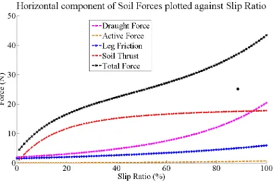
LPTPT - 2 enables the Forces / Slip relation to be plotted, giving insights into the dynamics of legged vehicle mobility, and illustrated in Fig. 5.
The plot demonstrates how total force available at the soil interface increases strongly with slip ratio. Unlike a wheeled rover, available traction will increase with slip provided sinkage is not so large as to overwhelm the rover.
Fig. 5.Force / Slip relation
3.3 Trafficability Prediction on Unknown Soils
In many cases in the field, precise information on the soil material’s in situ
physical properties will not be available; for example, whilst it may be possible to identify the soil (for example) as a coarse sand, its packing ratio may not be known or may vary as a result of wind and thermal action. Despite the lack of complete information, it may be possible to reliably predict performance using prior data sourced across a class of terrain materials.
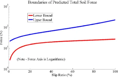
Figure 6 illustrates how a minimum trafficability performance could be de-termined, as follows:
(i) The characteristics of the type of soil identified are assessed (sandy, coarse or fine grained) , and the upper and lower bounds of the total force available plotted for all previously tested examples of that soil type; there should therefore be a high likelihood that the unknown soil example in the field has properties which fall within this range;
(ii) the lower bound position is assessed in the light of the demands on the vehicle - can forward progress still be made, allowing for any climbing required, at a moderate level of slip, by the application of forces at the leg / soil interface of an amount equal to or less than the minimum? This process may need to iterate to evaluate the effect of vehicle geometry changes (varied leg positioning) and gait modification;
(iii) If the answer is yes (subject to an appropriate safety margin), then an in principleassurance can be achieved that the vehicle will not become stuck, and can proceed with caution.
Fig. 6.Force Boundaries
4
Conclusions and Future Work
LPTPT is presented as a comprehensive tool to predict, analyse and quantify the forces available at the leg / soil interface of a walking rover. In LPTPT - 1 form, it enables maximum performance predictions to be made of a wide variety of vehicles operating on many soil types, and suggests that a legged rover, in addition to demonstrating superior agility over rough, rocky terrain, can also be an effective vehicle to traverse soft sands and other types of deformable materials. Incorporation of the Slip / Sinkage analysis in LPTPT - 2 enables the dy-namics of the Force / Slip relationship to be modelled, and shows that slip and associated sinkage, rather than being a disadvantage, can positively aid legged vehicle traction.
LPTPT can reduce the risk that incorrect “stop / go” decisions are made in challenging terrain scenarios, by increasing confidence that a traverse is feasible despit incomplete information on terrain physical characteristics.
Further improvements are envisaged using LPTPT - 2’s explicit derivation of force, slip, and sinkage relations to reduce the impact of unknown terrain parameters and enable improved performance to be achieved. Following a valid “go” decision, the vehicle would proceed with limited initial thrust application and employ on - line estimation of slip and sinkage to compare actual and pre-dicted slip and sinkage. The terrain parameters used in the model will be refined on - line based on this comparison, deriving a more accurate view of the terrain characteristics and enabling increased rover performance.
References
1. Raibert, M. et al: BigDog, the Rough-Terrain Quaduped Robot: Proceedings of the 17th World Congress The International Federation of Automatic Control Seoul, Korea, July 6-11, 2008.
2. Colombano, S. et al: Exploration of Planetary Terrains with a Legged Robot as a Scout Adjunct to a Rover. American Institute of Aeronautics and Astronautics, Space 2004 Conference, San Diego, California.
3. Bartch, S. et al: SpaceClimber: Development of a Six-legged Climbing Robot for Space Exploration, International Symposium on Robotics, 2010.
4. Scott, G. P. and Saaj,C. M.: Measuring and Simulating the Effect of Variations in Soil Properties on Microrover Trafficability, American Institute of Aeronautics and Astronautics, SPACE 2009 Conference, Pasadena, CA, 2009.
5. Bekker,M.: Introduction to Terrain Vehicle Systems, Part 1 - The Terrain & Part 2 - The Vehicle, University of Michigan Press, Ann Arbor, 1959.
6. McKyes,E.: Soil Cutting and Tillage, Elsevier Science Publishers, 1985.
7. Terzaghi, K.: Theoretical Soil Mechanics, 3rd Ed., John Wiley and Sons, Inc., London, 1943.
8. Reece,A. R.: The fundamental equation of earth-moving mechanics, Proceedings of the Symposium on Earthmoving Machinery, Vol. 179, Part 3F, 1965.
9. Grisso, R. D. et al: A soil tool interaction model for narrow tillage tools, 80-1518, American Society of Agricultural Engineers (ASAE), 1980.
10. Brunskill, C. and Lappas,V.: The effect of relative soil density on microrover traffi-cability under low ground pressure conditions, 11th European Regional Conference of the International Society for Terrain-Vehicle Systems, Bremen, Germany, 2009. 11. Wong, J.Y.: Theory of Ground Vehicles, 4th Edition, John Wiley & Sons Inc, New
York, 2008.
12. Janosi, Z. and Hanamoto,B.: The analytical determination of drawbar pull as a function of slip for tracked vehicles in deformable soils, ISTVS 1st Int. Conf. on Mechanics of Soil-Vehicle Systems, Edizioni Minerva Tecnica, Torino, Italy, pp. 707736.
13. Godbole, R. and Alcock, R.: A Device for the in situ Determination of Soil Defor-mation Modulus, Journal of Terramechanics, (32), no 4, pp 199 - 204, 1995. 14. Reece,A. R.: Problems of soil-vehicle mechanics, US Army Land Locomotion Lab,
ATAC, No. 8479, Mich: Warren; 1964
15. Richter, L. et al: A predictive Wheel-Soil Interaction Model for Planetary Rovers Validated in testbeds and Against MER Mars Rover Performance Data, ISTVS, Budapest, Hungary, 2006.
16. Lyasko,M.: Slip sinkage effect in soil-vehicle mechanics, Journal of Terramechanics 47 (2010) 21-31, 2010.
17. Ellery,A.: Environment-robot interaction - the basis for mobility in planetary micro-rovers, Robotics and Autonomous Systems 51, (2005) 29 - 39.