NOISE REDUCTION THROUGH CIRCULATION CONTROL Scott E. Munro*, K.K. Ahuja†, Robert J. Englar‡
Georgia Institute of Technology GTRI/ATASL
Atlanta, GA 30332-0844
Copyright 2001 by K. K. Ahuja and Scott Munro. Presented as at AIAA-2001-0666, at the 39th AIAA Aerospace Sciences Meeting & Exhibit, 8-1 January 2001.
*
Graduate Student, School of Aerospace Engineering, Student member, now at Naval Air Warfare Center, Weapons Division China Lake, CA 93555-6100.
Abstract
Circulation control technology uses tangential blowing around a rounded trailing edge or a leading edge to change the force and moment characteristics of an aerodynamic body. This technology has been applied to circular cylinders, wings, helicopter rotors, and even to automobiles for improved aerodynamic performance. Only limited research has been conducted on the acoustic of this technology. Since wing flaps contribute to the environmental noise of an aircraft, an alternate blown high lift system without complex mechanical flaps could prove beneficial in reducing the noise of an approaching aircraft. Thus, in this study, a direct comparison of the acoustic characteristics of high lift systems employing a circulation control wing configuration and a conventional wing flapped configuration has been made. These results indicate that acoustically, a circulation control wing high lift system could be considerably more acceptable than a wing with conventional mechanical flaps.
Nomenclature
a - Speed of sound c - Chord
cl - Airfoil lift coefficient
CCW - Circulation control wing
Cµ - qS V m j h - Slot height m - Mass flow p - Pressure q - ½ ρV2 (dynamic pressure)
R - Radial distance from jet exit to measurement location r - Radius of CCW surface
Re - Reynolds number SPL - Sound Pressure Level T - Temperature
V - Velocity α - Angle of attack
Θ - Polar angle (with respect to the flow axis) ρ - Density
Subscripts
T - Associated with tunnel freestream j - Associated with jet
o - Ambient condition
Introduction
One of the major environmental dilemmas facing today’s aircraft industry is noise pollution from aircraft, especially around the airport. There is a large emphasis on minimizing community noise due to operation of aircraft at and around the airport. Thus, airlines, aircraft manufacturers, NASA and the FAA have made reducing aircraft noise a priority. NASA has proposed a goal of lowering total aircraft noise emissions by 20 EPNdB by year 2020.
In order to meet this goal, NASA and other organizations have been encouraging innovative research to help reduce aircraft noise. Since a major contributor to aircraft noise on approach is airframe noise (or perhaps even on takeoff if the engine noise is eliminated), reducing this noise would be helpful in reaching the industry goals. The major airframe noise contributors are the landing gear, the slats, and the flaps. Much work has been done in these areas in the last five years in an effort to reduce their noise emissions. Of course, the best solution would be to have an aircraft without these protrusions into the flow field. Obviously an aircraft without landing gear would have serious drawbacks, but there are alternate high-lift systems that could replace conventional wing flaps and slats which have shown great promise in maintaining and even surpassing the lifting benefits of conventional flaps.
flap system of an aircraft.1 Over the years the CCW systems have gone through many
configuration designs for many different applications, including versions for rotorcraft, fighter aircraft, and short haul transports.1 However, there has been limited research conducted
investigating the possible acoustic benefits provided by such a system, other than occasional references to smaller noise footprints due to shorter take-off and landing distances. The only known work on acoustics of CCW is that of Salikuddin, Brown and Ahuja2 where they evaluated
the noise field of an upper surface blown wing with circulation control. That study, however, did not provide an indication of the acoustic benefits of a circulation control wing versus a conventional wing for the same lift.
Since CCW systems have already been shown as an adequate replacement for conventional flap systems in the aerodynamic realm,1 they are immediately a candidate for
reducing airframe noise since they eliminate much of the structure of the conventional flap system that protrudes into the flow. However, there are many issues that need to be resolved before the claims of lower noise are validated. Since the CCW system has never been evaluated on an acoustics basis, it must be optimized for this, while maintaining, at a minimum, the lift characteristics of a conventional system. The acoustic impact of several parameters must be investigated, such as the blowing slot height, slot velocity, and CCW geometric configuration (i.e., flap type and deflection angle). In order to correctly define the best combination, new areas of research will have to be investigated, including jet noise of extremely high aspect ratio nozzles, and the effects of jet turning on its noise propagation. These many issues are the motivation of the present study. The current work involves both experimental and computational efforts. Only experimental results are presented in this paper. Computational results are presented in Part II of this article and in Reference [3].
Background
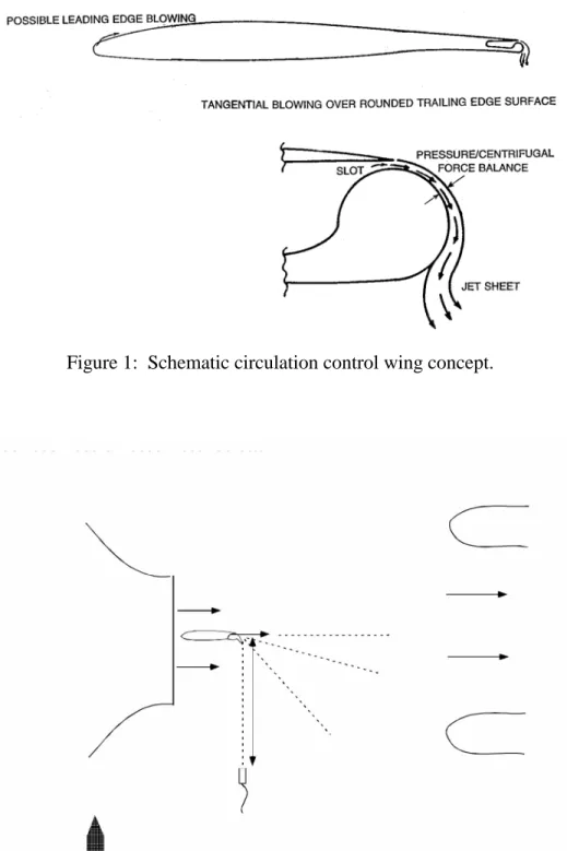
The circulation control wing (CCW) concept has been researched since the1960s. The CCW uses a rounded trailing edge (figure 1). 1 Air is blown tangentially along the upper surface
from a plenum supply inside the wing through a slot just upstream of the rounded trailing edge. Blowing moves the upper surface separation point around the trailing edge, thus changing the trailing edge stagnation point location, and hence the circulation for the entire wing. The higher-speed air moving along the surface also causes a suction peak in this region and contributes to increased lift.
The slot flow remains attached to the surface due to the so-called Coanda effect.4 At low
blowing velocities, the tangential blowing behaves similar to a boundary layer control device by adding energy to the slow moving flow near the surface. At higher blowing rates, the lift is increased by the change in circulation described above. A CCW can be designed without any mechanical moving elements if desired. This is achieved using a rounded trailing edge, where the amount of lift is controlled by the pressure valve to the supply plenum. This eliminates the need for flaps with hinges, tracks, screw drives and hydraulics.
The increment in lift generated is controlled by the non-dimensional parameter Cµ, defined using slot and freestream properties.
S q V m C s ∞ µ = or c q V m C s ∞ µ =
With a wing, the non-dimensionalizing area is the wing surface, S. For an airfoil, typically Cµ is given in Cµ/ft since the chord is the only available reference length. In general, a given Cµ will
the jet to separate prematurely. Thus, Cµ is used extensively in the literature when discussing circulation control.
The large circular trailing edges used in many of the early experiments evolved into a dual-radius hinged flap, mainly because the non-sharp trailing edge greatly increased drag.1,6, 7, 8
The hinged flap was a compromise of several desired features. The flap had a curved upper surface, like the cylindrical trailing edge, but a flat lower surface. This overcame the problem of high drag in cruise associated with the non-sharp trailing edge of the early designs. Overall, the hinged flap dual-radius design still maintained most of the circulation-control lift advantages but greatly reduced the drag problem associated with the circular trailing edge system.
The flap itself has several mechanical advantages compared to conventional Fowler flap systems. The flap is about ¼ to 1/3 the size of a conventional flap. This means lower flap weight, and thus fewer structural components are required to hold it in place.8 The flap is also a
simple hinged flap, rather than a complex Fowler type flap that requires complex gearing, tracks, and through gaps, which most likely contribute to airframe noise on their own. The reduced size and simplicity of the CCW system even with a small flap clearly offers some advantage over a conventional system.
There are many potential uses for circulation control. However, the two applications that have received the most research attention have been circulation control rotors (CCR) and CCW applied to an aircraft for short take-off and landing (STOL) capability. The reader is referred to references [1] and [5] where further details and citations on CCW research can be found. Some research pertinent to the present work is briefly mentioned below.
The Navy sponsored a full-scale flight test program on an A-6/CCW in the late 1970s. The design, tests and results are documented in references [9, 10 and 11]. Research has also
been done to investigate applying the circulation control system to a Boeing 737 type of aircraft. A summary of the effort is documented in reference [6]. The only known acoustic work on CCW configurations was performed by Salikuddin, Brown and Ahuja.2 There are other potential
uses for circulation control, including automotive applications1,12 and helicopters1,13 where noise
reduction may also be appropriate. The acoustic benefits shown in this paper should be applicable to other areas also.
Facilities and Instrumentation
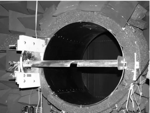
The anechoic flight simulation facility (AFSF) was used in the experiments. It is located at Georgia Tech Research Institute (GTRI) located at its Cobb County Research Facility in Smyrna, GA. The AFSF operates in an open jet wind tunnel configuration. It is an anechoic facility that allows acoustic measurements to be made in the presence of a freestream (see figure 2). The tunnel inlet has a square inlet which converges down to a 28-inch round duct. The duct terminates in an anechoic room as an open jet. Protruding out from the downstream wall is the collector, which is 4 ft. wide by 5 ft. high. The collector duct extends outside the building and ends at a centrifugal fan powered by a diesel engine. The facility is open circuit, drawing air from outdoors. The details of the facility can be found in references [14 and 15].
In the current experiments, the wings are mounted via mounting brackets to the open jet. This locates the wing across the jet opening immediately downstream of the end of the duct. Figure 3 shows one of the conventional wings mounted at the exit of the open jet. The ambient pressure in the chamber, the plenum pressure for the slot, pressures in the air supply line venturi
mass flow meter, and pressure in the inlet (for freestream velocity) were monitored on individual pressure transducers and manually recorded for each test point.
Acoustic measurements were made with B & K, 4135, ¼" microphones. One microphone was mounted on a traverse system that translated the microphone from angles of 30o
to 90o (where 0o is the freestream direction). This system was arranged to make all
measurements in the fly-over plane. The microphone was connected to a multi-channel digital frequency analyzer, which is run by software on a PC.
Figure 4 shows a schematic of the blowing system for the CCW. It consists of high-pressure ¾ inch tubing, a mass flow venturi, high-pressure gauges, and a muffler. On the upstream end, the tubing is connected to an existing high-pressure line with a control valve upstream. The flow passes through a mass flow venturi, and then goes through more tubing to an in-house built muffler which absorbs the upstream valve noise. Downstream of the muffler, the air passes through more tubing to inlets for the CCW plenum.
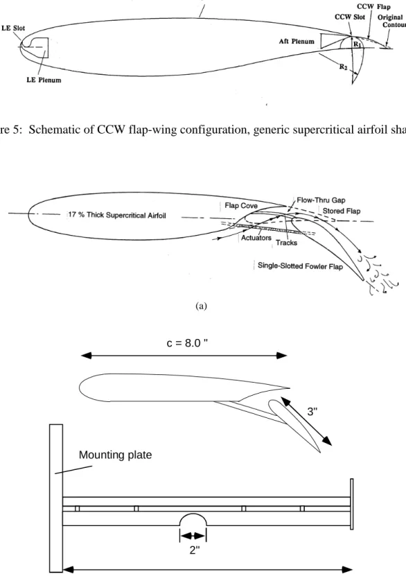
Test Models
The test model wing used in reference [6] was used as the test model for this study. This CCW model, shown in figure 5, has a supercritical baseline airfoil shape, but has many different detachable CCW trailing edge configurations. These included different sized flaps and cylindrical trailing edges. Based on past aerodynamic studies, the best overall aerodynamic characteristics were obtained with the small CCW flap configurations. The small deflectable flap allowed for low drag during cruise, but by blowing over the curved upper surface with the flap deflected, significant flow turning could still be achieved when desired. The highest lift
configuration was found to be with the flap deflected 90o. This was used as the starting
configuration for the current acoustic tests.
The conventional wing had the same general shape as the CCW over most of the chord. However, its trailing edge was altered with a cut-out for a stowed flap. A single-slotted Fowler flap was attached. Two different flaps were tested. The flap was deflected 30o or 40o from the
chord line to simulate a landing configuration. Both flaps spanned the entire wing, but one flap had a cut-out in at the mid-span point. Figure 6 shows the airfoil profile of the model and a drawing depicting the flap cut-out. Figure 3 is a photo of the model installed in the AFSF. The cut-out is to simulate the cut-outs on a real aircraft. Cut-outs are often present for structural reasons or to prevent engine exhaust from impinging on a lowered flap.
Technical Approach
The current work focused on optimizing a CCW system for low noise impact while maintaining aerodynamic performance sufficient for direct comparison to a conventional flapped wing configuration. The first step was to determine if and how a CCW configuration can have lower noise than a conventional system. This step involved side-by-side comparison of representative configurations under the same conditions, i.e., the same freestream flow and lift conditions. Since there are several variations of CCW systems that have been researched, a basic study of different CCW configurations was done. Since the test models were used in other aerodynamic experiments, this also allowed the use of this data when making the acoustic comparisons.
The optimized blowing configuration was compared with a conventional wing system. Basic noise spectra of the CCW and conventional wing configurations were acquired at several mean flow velocities and angle of attack. Specific cases where the different configurations had the same lift coefficient were then compared directly. Lift data from previous studies were used for this comparison.
Results and Discussion
Acoustic Optimization of Existing CCW State-of-the-Art Configurations
Since the CCW concept has been around for nearly 40 years, there have been many advances, changes, and modifications to the basic concept to improve its overall performance. To attempt to acoustically test all the different configurations would be unreasonable, since many of the changes were made to improve the system. There is little reason to acoustically test a system that is technologically surpassed by a better version. Thus, the goal of the current study is to investigate two or three of the best performing CCW configurations.
Based on previous aerodynamic work, the CCW with its flap deflected 90o was chosen as
the beginning point for the study (a possible high-lift configuration for landing approach). This had the best overall high-lift aerodynamic performance of several configurations tested in previous studies. The flap was eventually adjusted to 30o deflection to prevent flap-edge vortex
shedding noise that was present in the 90o case.
Six slot heights were chosen for the optimization study ranging from 0.003" to 0.020" These dimensions were chosen because they were typical slot heights used in earlier aerodynamic studies.6 A wide range of slot Mach numbers was evaluated, ranging from 0.3 to
1.2. The acoustically optimized CCW test configuration was compared with a conventional flap configuration. The conventional model had the same generic airfoil shape as the CCW, except near the trailing edge to accommodate the conventional flap. The flap chord was about 30% of the wing chord and deflected 40o to simulate a landing configuration. Data were acquired for
each test configuration at freestream speeds of 100, 150, 200, and 250 ft/s (nominal) and at geometric angles of attack of 0o, 7o, and 14.o
The majority of the data presented in this section was acquired at a geometric angle of attack of 0o and at the highest freestream velocity of about 240 ft/s unless otherwise noted.
Figure 7 shows acoustic spectra for several slot velocities with no freestream flow for the CCW with the 90o flap configuration. It shows a similar trend to the basic jet velocity scaling property
developed for round jets. For the measured velocities, V8 scaling of jet noise theory16 predicts
about a 19 dB increase between the two most extreme cases, which is similar to that measured (about 16 dB) above 2 kHz. Some noise due to scrubbing of the slot jet over the flap surface is likely to be present as well.
It appears that the majority of the noise is associated with the jet noise from the slot and not due to internal model and facility noise associated with the blowing system above 2 kHz. However, below 2 kHz the scaling is not followed in the data. This is most likely due to internal noise that is generated from the flow into the wing on its way to the slot. This contaminates the signal making the noise higher for the lower slot velocities, but not affecting the higher velocities where the jet mixing noise is expected to be dominant. Thus, the difference between the data is less than predicted by the theory. This is supported by figure 8.
in the flow path remain the same. Since the mass flow into the wing must be the same as the mass flow out, the doubling of the exit area roughly causes a doubling of the mass flow at the exit, and hence a doubling of the mass flow inside the wing. However, since all the areas inside the wing are constant, the velocity must double inside the wing in order to double the mass flow. Thus, if noise is dominated by the internal noise it should follow a sixth power law of the internal velocity, as this noise is expected to be dipole like in nature. If so, the data should reflect an 18 dB increase. However if the noise is dominated by externally produced jet mixing noise, then it will change only to the extent that the exit area has changed. Based upon the available experience/theory on round jets16 this will provide for the jet mixing noise intensity
proportional to slot exit area. This translates into a 3 dB increase in noise after shifting the spectrum for h = 0.006" to the left over the spectrum for h = 0.012" by a factor of one octave to allow for the shift in the noise frequencies proportional to a characteristic length. This number is somewhat smaller than the observed difference in the SPL’s of the two spectra in figure 8. All of these arguments assume that we can apply the lessons learned from round jets to very high aspect-ratio jets. Yet, since the noise increase is of the order of 3 dB, it can be said that internal noise is not significant in this case. The fact that the observed difference in spectral SPL’s is more than the expected 3 dB could also be associated with the scrubbing noise of the CCW slot jet moving over the rounded edge. If so, it is genuinely produced outside and is not contaminated by any internal noise. Obviously, some clarification of the data is needed. To fully understand the jet noise characteristics of extremely high aspect-ratio jets without the internal noise concerns discussed here, we have fabricated a high aspect ratio nozzle (HARN). We reserve our full judgment until additional studies have been carried out on the HARN, which is being tested by the authors in an acoustically clean facility
We believe that, the data may be contaminated by noise generated internal to the wing below about 2 kHz. A muffler was built and installed in the supply line downstream of all valves to eliminate as much upstream noise as possible. However, due to the small thickness of the wing, inlets into the wing plenum are smaller than desired. This results in a relatively high velocity flow entering into the plenum with no space to absorb the noise generated.
It is believed that these noise sources may be causing a majority of the noise below 2 kHz where the noise is not following the typical V8 jet noise scaling. For the time being, this will be
noted and data below 2 kHz will be disregarded as either somewhat corrupted by internal noise or not understood until HARN data becomes available.
Figure 9 shows the noise spectra for several slot jet velocities at a constant freestream velocity and constant slot height of 0.003" There are several things to note. First, with no blowing there is a large-amplitude well-defined tone. It is also important to note that in general the very low frequency noise ( f ~< 4 kHz) is much greater compared to the data in figure 7. Some of this is from the tunnel noise itself ( below about 500 Hz) but most of it is flow noise associated with the freestream flow around the wing. The tone is believed to be due to the shedding of vortices off the bluff trailing edge of the deflected flap. Notice that blowing, even at low slot jet velocities, significantly reduces the magnitude of the tone. However in this case it is not completely eliminated, in fact it dominates the spectra at all blowing velocities.
The tone mentioned above was unexpected. This presented a problem since the tone dominated the spectrum at all blowing conditions, thus any acoustic benefit derived from using the CCW over a conventional wing would be lost if the flap were deflected to 90o. Because of
Figure 10 shows two curves with the flap set to 30o. In this case notice that the tone is
completely eliminated with a small amount of blowing. The computational study also produced the same result, and is presented in reference [3]. Not only is this advantageous for the current study, but this result could be used in other applications where similar shedding produces a distinct tone.
Data for test conditions similar to those for the 90o deflection are shown in figure 11.
Again, with no blowing the tone is present. However, with small amounts of blowing the tone is completely eliminated. Since this configuration showed more promise, the remaining parameters were optimized using the 30o flap configuration. Both slot height and slot jet velocity were
examined.
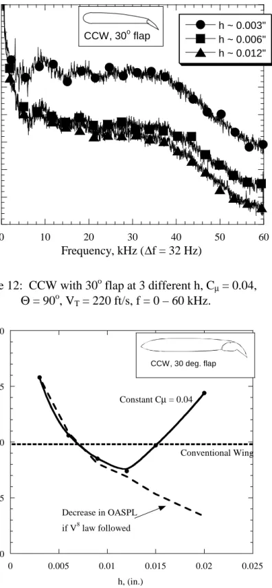
The effect of slot height was investigated next. Figure 12 shows data with similar freestream conditions but different slot heights. It is important to note that this figure compares different CCW configurations with the same lift. For the same Cµ at different h, the slot velocity will be different since Cµ is dependent on mass flow from the slot. Since the goal is to compare the same lift, it is best to look at the data where Cµ is constant since the same Cµ will give the same lift in most cases. There is some variation of lift with h for high Cµ, but in the Cµ range of interest here, h does not have an independent affect on the results. Thus, the data in figures 12 shows that there is a lower noise from the larger slot heights for a given lifting condition. This makes sense since Cµ is proportional to mass flow through the slot. By increasing the slot height but maintaining the same mass flow (and hence same Cµ) the jet velocity of the slot is lower. At this point it appeared that the most appropriate conditions for comparing a CCW system to a conventional system had been found. Maximize the slot height so that jet velocity is minimized.
Unfortunately it was found that above a slot height of about 0.012" the noise began to increase (for constant Cµ). Since this was contrary to the logical trend associated with what should be happening, some attention was given as to why this was happening. If one looks more closely at Cµ it contains a mass flow term. Initial results indicated that reducing the slot velocity reduced the noise. In the equation this means that Vs would decrease. If one defines the mass
flow term based on the mass flow “in” rather than “out” the problem becomes evident.
qC V ) V A ( qC V m qC V m C = s s = in s = ρin in in s µ
Density will vary with the pressure in the plenum, (ρ = P/RT), but it varies proportionally to slot velocity (as Vs decreases, P decreases, and hence ρ decreases). Area is constant in the plenum regardless of slot height. Thus, in order to offset the decrease in Vs and ρ, Vin must increase. When this occurs, the internal noise associated with internal velocities will also increase. Figure 13 shows OASPL plotted versus h for constant Cµ. If it is assumed that the highest slot velocity is dominated by external jet noise, the decrease in noise due to falling Vs can also be plotted. In
the figure the highest Vs occurs at the smallest h. The drop in OASPL should follow the V8
scaling law. However, in this case keep in mind that the slot velocity drops due to an increase in slot area. Thus the final estimated curve shows dropping OASPL due to slot velocity, but at a lower rate than V8 because of an increase in slot area.
Notice that the experimental data follows V8 scaling for some time but eventually
increases away from the estimated drop off. It is believed that this increase is due to the increasing dominance of internal noise as the slot velocity is reduced while the internal velocity is increased.
Although this finding was unfortunate it was not terribly detrimental to the study as long as one keeps in mind that proper design of the internal system will decrease the CCW noise further (in essence it should continue to drop along the estimated slot velocity curve in figure 13 as the slot velocity is decreased). Thus, any benefit found will be enhanced with careful design of the internal system.
Determining an “equal lift” condition
The next step was figuring out how to compare the two lift augmentation systems. Aerodynamic data from previous studies was used for this (specifically that in reference [6]). Aerodynamic data was available for both conventional wing configurations and the CCW in the form of lift curves (cl vs α curves). This was convenient since for a CCW, a given Cµ will generally provide a ∆cl over the entire angle of attack range (not including the extreme high jet velocities and large slots where the jet separates from the surface). Thus, once the lift for the unblown CCW was found, this could be compared to the cl for the conventional airfoil and the needed ∆cl was be calculated by subtracting the two values. This ∆cl was then used to determine the Cµ needed to match lift provided by the conventional wing flap system. Essentially each Cµ is analogous to a flap setting which shifts the baseline lift curve by a given amount. For the particular CCW configuration (CCW with flap at 30o), a Cµ of about 0.04 produced about the same amount of lift as the conventional wings used in the experiments.
CCW versus Conventional Wings
except for a cut-out region in center span (figure 6 for a drawing figure 3 for a photo of it installed in the AFSF). These wings are the same basic airfoil shape as the CCW. The wings were tested at the same flow conditions as the CCW.
Initially, the conventional wing with the 30o flap was tested. Figure 14 shows a
comparison between the conventional wing with the 30o flap and the CCW configuration with
lowest noise for the equivalent lift case. Since the h ~ 0.012" data was the minimum CCW noise condition, it is presented in the figure. In the range between 1 kHz and 10 kHz, the CCW has noise levels similar to those of the conventional system. Unfortunately, this was not the desired result, although it does provide assurance that using the CCW system does not increase the noise to the environment in its minimum noise configuration.
However, many aircraft have a cut-out in flaps across the span. This difference contributes a fair share of noise to a conventional wing system since flap edge noise has been identified as a major contributor to airframe noise. Thus, this wing was missing a noise source that would most likely be greatly reduced in a CCW system. Since the CCW flap is much smaller, there is no need for a gap in the flap to avoid engine exhaust. Its small size would also in many cases reduce the need for gaps due to structural concerns. Thus the CCW system with a full span flap is not unreasonable.
Acoustic tests were performed on the new configuration similar to the previous tests. Figure 15 shows the comparison of the wing with the cut-out flap with the CCW. As expected, the cut-out in the flap increased the noise on the conventional system significantly and shows a significant advantage to using a CCW system in the region below 10 kHz and some advantage up to 40 kHz. Beyond 40 kHz the two systems have similar noise levels. The data in this figure and
spectrum where there are differences between the two systems. Similar results can be seen at other freestream velocities and angles of attack, however, the magnitude of the difference varies some depending on the conditions.
Up to this point, only data from a microphone at Θ = 90o has been shown. This is only part of the noise picture, the changes in directivity of the noise between the two systems must be compared as well. Data were acquired at 30o, 60o, and 90o. It should be noted that there are
some differences depending on the angle. Note that the 60o and 90o positions do not actually
have a line-of-sight path to the slot exit which is located on the top surface of the wing. It is also worth noting that the jet from the slot leaves the trailing edge of the wing at about Θ = 56o. Even with freestream velocity, the jet stays relatively close to that angle for some time beyond the trailing edge of the wing.
Figure 16 compares the data for the two wing systems at Θ = 30o and Θ = 60o. At 30o the CCW system produces no real advantage over a conventional system. However there is still some noise reduction in favor of the CCW system at 60o, similar to the 90o data shown earlier.
These results indicate that a CCW system certainly has potential for reducing airframe noise. The results also show some trends of high-aspect-ratio jets, however there is still much left to study and resolve before all the aspects of the circulation control wing noise issues are solved and helpful to the design of a practical low noise CCW system.
In order to resolve some of the questions brought up by the CCW and to eliminate the possibility of internal noise contamination, a high aspect-ratio nozzle has been designed and fabricated. This nozzle is presently being tested by the authors in an anechoic facility and the intent is to produce a database of quality high aspect-ratio jet noise data that can be used to verify the speculations about internal noise in the experiments presented here. In addition this data will
be used to augment the present results by demonstrating the even greater benefits possible for a CCW high lift configuration in reducing airframe noise.
Conclusions
Due to the great interest in reducing aircraft noise, an innovative concept for eliminating a conventional flap system has been tested for its possible acoustic advantages. Previous studies have shown that the circulation control wing is an aerodynamically viable alternate for conventional mechanical flaps. This study shows that there is also a substantial advantage in the acoustic realm. The results presented showed a lower noise spectrum for a CCW system compared to a conventional system for the same lifting condition. It should be noted that even if the CCW produces noise comparable to that of a conventional wing it is an advantage. This is because a CCW is expected to be much lighter than a conventional wing.
It was also noted that the internal noise of the CCW blowing system of the model inhibited finding the full possible advantage a CCW system can offer. It is believed that careful design of a CCW blowing system, including internal details, could further improve the results shown here.
Tests are also ongoing on a very high aspect ratio nozzle to verify the characteristics and scaling of high aspect ratio rectangular nozzles similar to what is found in a CCW blowing slot. These results will provide a greater understanding of this type of jet.
Acknowledgments
This work was sponsored by NASA Grant -NAG1 - 2146 through NASA Langley, under its Breakthrough Innovative Technology Program. The authors are grateful to Dr. L. Sankar of the AE school for many helpful discussions. Thanks are also due to Mr. C. Jameson for designing the HARN nozzle and to Dr. Rick Gaeta for his assistance in the experiments and many useful discussions.
References
1. Englar, Robert J., “Cicrulation Control Pneumatic Aerodynamics: Blown Force and Moment Augmentation and Modification;, Past, Present & Future.” AIAA Paper 2000-2541, Fluids Conference, Denver, CO, June, 2000.
2. Salikuddin, M. Brown, W.H., and Ahuja, K.K. “Noise from a Circulation Control Wing with Upper Surface Blowing,” Journal of Aircraft, Vol. 24 No. 1, January, 1987.
3. Liu, Yi, Sankar, Lakshmi N., Englar, Robert J., Ahuja, Krishan K. “Numerical Simulations of the Steady and Unsteady Aerodynamic Characteristics of a Circulation Control Wing.” AIAA paper 2001-0704. January, 2001.
4. Dunham, J. “A theory of circulation Control by Slot-Blowing Applied to a Circular Cylinder,” Journal of Fluid Mechanics, Vol. 33 Part 3, pp 495-514, 1968
5. Englar, Robert J., Applegate, Constance A. “Circulation control - A Bibliograhpy of DTNSRDC Research and Selected Outside References: January 1969 through December
1983,” David W. Taylor Naval Ship Research and Development Center, DTNSRDC-84/052, 1984
6. Englar, Robert J., Smith, Marilyn J, Kelley, Sean M. and Rover, Richard C., III. “Development of Circualtion Control Technology for Application to Advanced Subsonic Transport Aircraft,” AIAA Paper 93-0644, presented at AIAA Aerospace Sciences Meeting, January, 1993.
7. Englar, R.J. and Huson, G.G. “Development of Advanced Circulation Control Wing High Lift Airfoils,” AIAA paper 83-1847, presented at AIAA Applied Aerodynamics Conference, July, 1983.
8. Englar, Robert J. “Low-Speed Aerodynamic Characteristics of a Small, Fixed Trailing-Edge Circulation Control Wing Configuration Fitted to a Supercritical Airfoil,” David W. Taylor Naval Ship Research and Development Center, DTNSRDC/ASED-81/08, March 1981. 9. Nichols, J.H. Jr, Englar, R.J., Harris, M. J., Huson, G.G. “Experimental Development of an
Advanced Circulation Control Wing System for Navy STOL Aircraft,” AIAA paper 81-0151, presented at AIAA Aerospace Sciences Meeting, January, 1981..
10. Pugliese, A. J., and Englar, R. J. “Flight Testing the Circulation Control Wing,” AIAA paper 79-1791, presented at AIAA Aircraft Systems and Technology Meeting, New York, August, 1979.
11. Nichols, J.H., Jr. et al. “Development of High Lift Devices for Application to Advanced Navy Aircraft,” Report DTNSRDC-80/058, AD A084-226, April, 1980.
12. Lane, Paul Jr. “Ground Controls,” Racecar Engineering, Vol. 9 No. 8, pp 20-23, October 1999.
13. Reader, Kenneth R. “Hover Evaluation of the Circulation Control High Speed Rotor,” David W. Taylor Naval Ship Research and Development Center, Report 77-0034, June 1977 14. Ahuja, K.K., Tanna, H.K., and Tester, B.J. “An experimental Study of Transmission,
Reflection and Scattering of Sound in A Free Jet Flight Simulation Facility and Comparison with Theory,” Journal of Sound and Vibration, 75 (1), pp 51-85, 1981
15. Ahuja, K. K., Tester, B. J., and Tanna, H. K., “The Free Jet as a Simulator of forward Velocity Effects on Jet Noise.” NASA Contractor Report # 3056, 1978.
16. Ahuja, K.K., and Bushell, K.W. “An Experimental Study of Subsonic Jet Noise and Comparison with Theory,” Journal of Sound and Vibration, 30 (3), pp 317-341. 1973.. 17. Tam, C.K.W. and Zaman, K.B.M.Q., “Supsonic Jet Noise from Non-Axisymmetric and
Tabbed Nozzles.” AIAA Paper 99-0077, 1999.
18. Tam, Christopher K.W., Auriault, Laurent, “Jet Mixing Noise from Fine Scale Turbulence.” AIAA Paper 98-2354, 1998.
19. Tam, C.K.W., Golebiowski, M. and Seiner, J.M., “On the Two components of turbulent Mixing Noise from Supersonic Jets.” AIAA Paper 96-1716, 1996.
20. Tam, Christopher K.W., “Influence of Nozzle Geometry on the Noise of High Speed Jets.” AIAA paper 98-2255, 1998.
21. Ahuja, K.K. “Correlation and Prediction of Jet Noise,” Journal of Sound and Vibration, 29 (2), pp 155-168, 1973.
Figure 1: Schematic circulation control wing concept.
Figure 3: Photo of a conventional wing mounted in AFSF.
X 300 psi Supply
Regulating
Valve Muffler
Two Inlets to W ing
3/4" Flexible Tubing 2" H igh Pressure
Piping 1" H igh Pressure
Piping
Mass Flow Venturi
Figure 5: Schematic of CCW flap-wing configuration, generic supercritical airfoil shape.. (a) 2" c = 8.0 " 3" 30" Mounting plate (b)
35 40 45 50 55 60 65 70 75 0 5 10 15 20 V s = 660 ft/s V s = 875 ft/s V s = 1013 ft/s V s = 1158 ft/s SPL ( P re f = 20 X 10 -6 Pa ) Frequency, kHz (∆f = 32 Hz) CCW, 90o flap
V8 scaling predicts ~19 dB increase
Figure 7: CCW blowing system noise spectra with no freestream flow. VT = 0 ft/s, h = 0.006" 20 25 30 35 40 45 50 55 60 0 10 20 30 40 50 60 h ~ 0.006" h ~ 0.012" Frequency, Hz (∆f = 32 Hz) SPL ( P re f = 20 X 10 -6 Pa)
50 60 70 80 90 100 110 0 1 2 3 4 5 V s = 0 ft/s V s = 660 ft/s V s = 860 ft/s V s = 1008 ft/s V s = 1112 ft/s Frequency, kHz (∆f = 32 Hz) CCW, 90o flap SPL (P ref = 20 X 10 -6 Pa) (a) 30 40 50 60 70 80 90 100 0 10 20 30 40 50 60 V s = 0 ft/s V s = 660 ft/s V s = 860 ft/s V s = 1008 ft/s V s = 1112 ft/s Frequency, kHz (∆f = 32 Hz) CCW, 90o flap SPL (P ref = 20 X 10 -6 Pa) (b)
Figure 9: CCW with 90o flap and freestream velocity, Θ = 90o, VT = 220 ft/s, (a) f = 0 – 60 kHz, (b) f = 0 – 5 kHz.
50 60 70 80 90 0 1 2 3 4 5 V s = 0 ft/s V s = 660 ft/s SPL (P ref = 20 X 10 -6 Pa ) Frequency, kHz (∆f = 32 Hz) CCW, 30o flap
Figure 10: CCW with 30o flap and freestream velocity, Θ = 90o, VT = 220 ft/s, f = 0 – 5 kHz. 20 30 40 50 60 70 80 0 10 20 30 40 50 60 V s = 0 ft/s V s = 660 ft/s V s = 880 ft/s V s = 1016 ft/s V s = 1116 ft/s SPL (P re f = 20 X 10 -6 Pa) Frequency, kHz (∆f = 32 Hz) CCW, 30o flap
30 35 40 45 50 55 60 65 70 0 10 20 30 40 50 60 h ~ 0.003" h ~ 0.006" h ~ 0.012" Frequency, kHz (∆f = 32 Hz) CCW, 30o flap SPL (P ref = 20 X 10 -6 Pa )
Figure 12: CCW with 30o flap at 3 different h, Cµ = 0.04, Θ = 90o, VT = 220 ft/s, f = 0 – 60 kHz. 70 75 80 85 90 0 0.005 0.01 0.015 0.02 0.025 OASPL (fro m 1 k Hz - 2 0 k Hz) (P re f = 20 X 10 -6 Pa ) h, (in.) CCW, 30 deg. flap Constant Cµ = 0.04 Decrease in OASPL if V8 law followed Conventional Wing
20 30 40 50 60 70 0 10 20 30 40 50 Conventional wing, δ f = 30 o CCW, h = 0.012", C µ = 0.04 Frequency, kHz (∆f = 32 Hz) SPL ( P ref = 20 X 10 -6 Pa)
Figure 14: CCW and conventional wing 2-d flap at similar lift condition. Θ = 90o, VT = 220 ft/s 20 30 40 50 60 70 80 0 5 10 15 20 25 30 35 40
Conventional wing, cut-out, δ
f = 40 o CCW, h = 0.012", C µ = 0.04 Frequency, kHz (∆f = 32 Hz) SPL ( P ref = 20 X 10 -6 Pa)
Figure 15: CCW and conventional wing with cut-out at similar lift condition. Θ = 90o, VT = 220 ft/s
20 30 40 50 60 70 80 0 10 20 30 40 50
Conventional wing, cut-out, δ
f = 40 o CCW, h = 0.012", C µ = 0.04 SPL (P re f = 20 X 10 -6 Pa) Frequency, kHz (∆f = 32 Hz) Θ = 60o (a) 20 30 40 50 60 70 80 0 10 20 30 40 50 60
Conventional wing, cut-out, δ
f = 40 o CCW, h = 0.012", C µ = 0.04 Frequency, kHz (∆f = 32 Hz) Θ = 30o SPL (P re f = 20 X 10 -6 Pa) (b)
Figure 16: CCW and conventional wing with cut-out at similar lift condition.