User Guide
PipeFlow is a trading name of Daxesoft Ltd. www.pipeflow.com www.pipeflow.co.uk
Copyright Notice
© 2015 All Rights Reserved Daxesoft Ltd.
Distribution Limited to Authorized Persons Only. Trade Secret Notice
The PipeFlow.com, PipeFlow.co.uk and Daxesoft Ltd. name and logo and all related product and service names, design marks, logos, and slogans are either trademarks or registered trademarks of Daxesoft Ltd. All other product names and trademarks contained herein are the trademarks of their respective owners.
Printed in the United Kingdom - October 2015
Information in this document is subject to change without notice. The software described in this document is furnished under a license agreement. The software may be used only in accordance with the terms of the license agreement. It is against the law to copy the software on any medium except as specifically allowed in the license agreement. No part of this document may be reproduced or transmitted in any form or by any means electronic or mechanical, including photocopying, recording, or information recording and retrieval systems, for any purpose without the express written permission of Daxesoft Ltd.
Table of Contents
Table of Contents ... 3
Table of Figures ... 9
Introduction... 12
Pipe Flow Expert Software... 12
Pipe Flow Expert Software Overview ... 13
Minimum Operating System Requirements ... 14
Registration and Licensing Information ... 15
Contacting Pipe Flow Software ... 18
Additional Pipe Flow Software Programs ... 18
Interface and Menus ... 19
Menu Bar... 19 File Menu ... 20 Edit Menu ... 22 Units Menu ... 23 Fluid Menu ... 23 Drawing Menu ... 25 Tools Menu ... 26 License Menu ... 26 Documentation Menu ... 27 Help Menu ... 28 Tool Bar... 29
Tool Bar Buttons ... 29
Keyboard Shortcuts ... 33
Node Pane ... 33
Node Types ... 33
Tank Node Data ... 34
End Pressure Data ... 35
Join Point Data ... 36
Flow Demands ... 37
Pipe Pane ... 38
Pipe Features ... 38
Pipe Material Data ... 40
Pipe Diameter Data ... 42
Pipe Fittings Database ... 44
Control Valve Data ... 48
Pump Data ... 49
Drawing Pane ... 51
Configuration Options Screen ... 53
Labels Tab ... 53
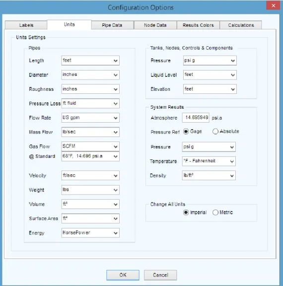
Units Tab ... 55
Pipe Settings Tab ... 57
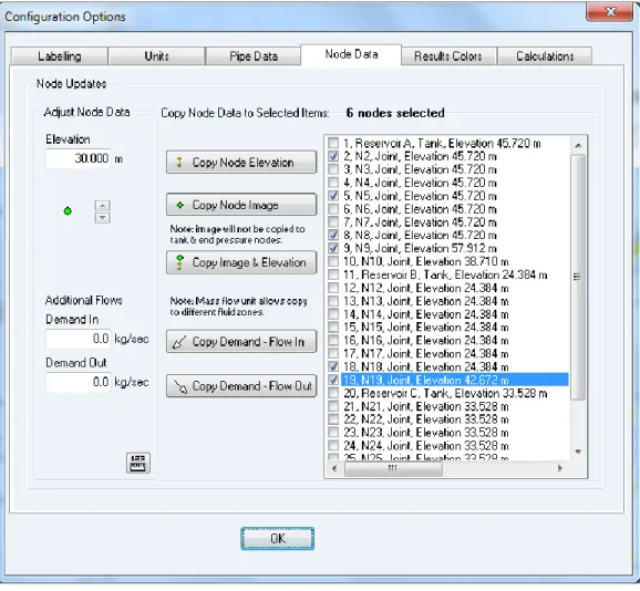
Node Updates Tab ... 59
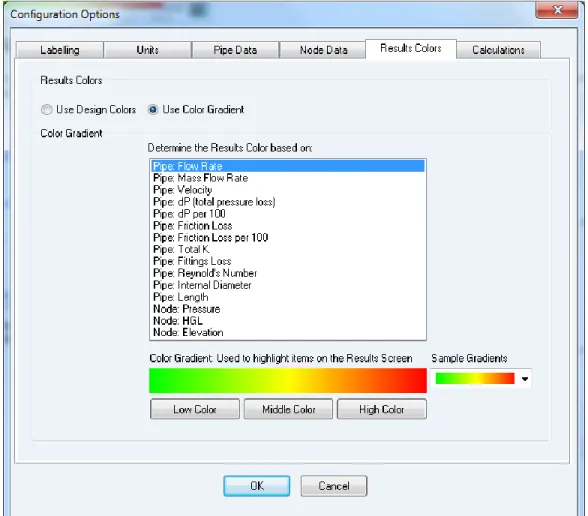
Results Colors Tab ... 60
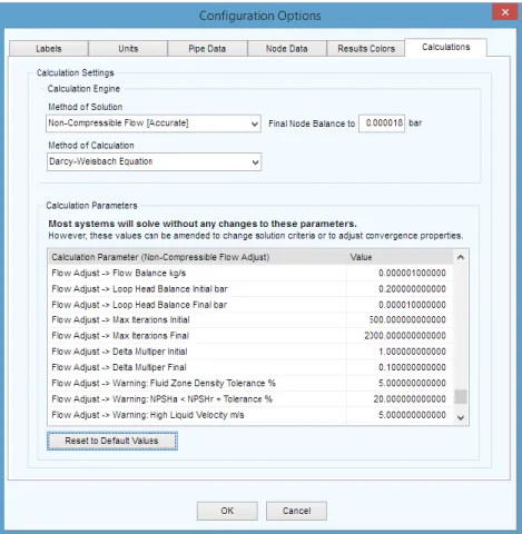
Calculations Tab ... 61
Results Tables ... 62
Viewing Individual Results ... 64
File and Design Operations... 65
Tabbed Design Sheets ... 65
Creating a New Pipe System ... 65
Isometric System Options ... 66
Designing a Pipe System ... 66
Saving a System ... 67
Change the System View - Isometric Mode Toggle ... 68
Sending a System via E-mail ... 68
Printing a System ... 68
Saving a Screen Image ... 70
Saving a Drawing to an EMF Image ... 70
Emailing a Screen Image ... 70
System Options ... 71
Choosing Units (imperial / metric) ... 71
Choosing Item Labelling ... 72
Choosing the System Units... 73
Choosing Pipe Drawing Defaults ... 74
Change attributes of more than one pipe ... 78
Node Updates ... 80
Results Colors ... 81
Configuring the Calculation Parameters ... 82
Fluid Zones... 84
Defining Fluid Zones ... 84
Properties of Mixed Fluids ... 85
Two Phase Flow – Additional Pressure Drop ... 85
Fluids Database ... 86
Tanks ... 89
Add a Tank ... 89
Nodes (Join Points) ... 91
Adding a Node ... 91
Pipes ... 93
Adding a Pipe ... 93
Adding a Pipe Material to the Database ... 96
Adding Pipe Size Data to the Database ... 96
Reversing the Pipe Flow ... 97
Closing a Pipe in the System ... 97
Using the Pipe Sub-menu while drawing ... 98
Preventing Backflow in a pipe ... 99
Using the Default Pipe feature while drawing ... 99
Fittings and Valves ... 100
Adding a Fitting to a pipe ... 100
Adding a Fitting to the Database ... 102
Components ... 105
Adding a Component with a pressure loss ... 106
Cv and Kv Flow Coefficients ... 109
Adding a component/valve with a Cv or Kv value ... 109
Sprinkler K factors ... 112
Modeling a Spray Nozzle with a Sprinkler K Factor ... 113
Control Valves (FCV, PRV, BPV) ... 114
Adding a Flow Control Valve... 115
Adding a Pressure Reducing Valve ... 116
Adding a Back Pressure Valve ... 117
Pumps ... 119
Adding a Pump ... 119
Adding a Fixed Flow Rate Pump ... 121
Note about Fixed Flow Rate Pumps ... 122
Adding a Fixed Head Increase Pump ... 122
Adding a Fixed Speed Pump Curve ... 123
Working with Pump Curve Graph ... 126
Import Pump Curve Image ... 128
Variable Speed and Change to Impeller Size ... 131
Predicted Performance Data... 132
Search Pump Database ... 135
Example Pumps (with Flow versus Head curve) ... 137
Demand Flows ... 138
Adding a Demand Flow at a join point ... 138
Demand Pressures ... 140
Adding a Demand Pressure at an end node... 140
Text Items... 142
Adding Text to the drawing ... 142
Images ... 144
Importing Images on to the drawing ... 144
Viewing, Modifying, and Deleting Items ... 146
Zooming in or Out in the Drawing Pane ... 146
Zooming in to a Selected Area ... 146
Viewing the whole System in the Drawing Pane ... 147
Panning a System in the Drawing Pane ... 147
Finding a Pipe or a Node ... 148
Mirror View of the Pipe System ... 148
Inverted View of the Pipe System ... 148
System Amendments and Group Updates ... 149
Using the Edit Grid ... 149
Individual Item Viewing and Modifying ... 150
Group Updates on the Drawing ... 151
Moving Components in a System ... 152
Cutting, Copying, and Pasting Nodes & Pipes ... 153
Copying Between Drawings ... 154
Opening Additional Systems ... 154
Rotating Selected Items ... 155
Moving a Pipe to link at a new position ... 155
Using the Undo and Redo Functions ... 156
Deleting Components in a System ... 156
Deleting a Node or Pipe ... 156
Deleting a Group of Components ... 157
Deleting a Demand Flow ... 157
Deleting Fittings ... 158
Deleting a Component Pressure Loss ... 158
Deleting a Control Valve ... 159
Deleting a Pump ... 159
Calculations and Results ... 160
Automatic Checks and Updates ... 161
Viewing the System Results ... 169
Saving the System Results ... 169
Exporting the System Results ... 170
Redesigning the System ... 171
Amending the System ... 171
Create a PDF Report of the System Results ... 172
Calculation Theory and Method of Solution ... 174
Fluid Flow States ... 174
Fluid Viscosity ... 174
Reynolds Numbers ... 175
Friction Factors ... 175
Colebrook-White Formula ... 175
Friction Losses (resistance to flow) ... 175
Darcy-Weisbach Formula ... 176
Compressible Gas Flow Equations ... 176
Fitting Head Loss ... 177
’K’ Factor fitting head loss calculation ... 177
Calculate Total Pressure Loss ... 177
Energy and Hydraulic Grade Lines ... 178
Balanced Flow State ... 178
Loops, Nodes and Pipes ... 179
Solving the Flow versus Pressure Loss Balance ... 180
System Calculation Tolerances ... 181
System Components ... 181
Cv and Kv Flow Coefficients ... 181
Sprinkler K Value Coefficients ... 187
Flow Control Valves ... 188
Pressure Reducing Valves... 188
Back Pressure Valves ... 190
Pumps (with Flow versus Head Curve) ... 191
Fixed Flow Rate Pumps ... 191
Fixed Head / Pressure Rise Pumps ... 192
Net Positive Suction Head available ... 192
Two Phase Flow ... 192
Slurries ... 192
Working with Compressible Fluids ... 193
Using Compressible Flow Equations ... 194
Glossary ... 198 Index ... 199
Table of Figures
Figure 1 Pipe Flow Expert License Software ... 15
Figure 2 Pipe Flow Expert interface ... 19
Figure 3 Menu Bar ... 19
Figure 4 File Menu ... 20
Figure 5 Edit Menu ... 22
Figure 6 Units Menu ... 23
Figure 7 Fluid Menu ... 23
Figure 8 Drawing Menu ... 25
Figure 9 Tools Menu ... 26
Figure 10 License Menu ... 26
Figure 11 Documentation Menu ... 27
Figure 12 Help Menu ... 28
Figure 13 Tank Node Pane ... 34
Figure 14 End Pressure Node Pane ... 35
Figure 15 Join Point Node Pane ... 36
Figure 16 Flow Demands ... 37
Figure 17 Pipe Pane and Pipe Sub-menu ... 38
Figure 18 Pipe Material Data ... 40
Figure 19 Pipe Diameter Data ... 42
Figure 20 Pipe Fittings Database ... 44
Figure 21 Component Pressure Loss ... 46
Figure 22 Control Valve Data ... 48
Figure 23 Pump Data ... 49
Figure 24 Drawing Panes Standard or Isometric ... 52
Figure 25 Configuration Options - Labels Tab ... 53
Figure 26 Configuration Options - Units Tab ... 55
Figure 27 Configuration Options - Pipe Settings Tab ... 57
Figure 28 Configuration Options - Node Updates Tab ... 59
Figure 29 Configuration Options - Results Colors tab ... 60
Figure 30 Configuration Options - Calculations Tab ... 61
Figure 31 Results tables ... 62
Figure 32 View Individual Results ... 64
Figure 33 Save As dialog ... 67
Figure 34 Printing Information dialog ... 69
Figure 36 Configuration Options – Units tab ... 73
Figure 37 Configuration Options – Pipe Settings tab ... 74
Figure 38 Pipe diameter data - materials list ... 75
Figure 39 Pipe Diameter Data - Pipe Sizes ... 76
Figure 40 Pipe fitting friction coefficients ... 77
Figure 41 Configuration Options – Pipe Settings Tab ... 78
Figure 42 Configuration Options – Node Updates Tab ... 80
Figure 43 Configuration Options – Results Colors Tab ... 81
Figure 44 Calculation settings ... 83
Figure 45 Fluid Zone Menu ... 84
Figure 46 Fluid Database ... 86
Figure 47 Properties of Gases ... 88
Figure 48 Node Pane for Tanks ... 89
Figure 49 Node Pane for Join Points ... 91
Figure 50 Set Flow Demands... 92
Figure 51 Pipe diameter data - materials list ... 94
Figure 52 Pipe diameter data - pipe sizes ... 95
Figure 53 Pipe Sub-Menu ... 98
Figure 54 Pipe fitting friction coefficients database ... 101
Figure 55 Add a fitting in the Pipe fitting friction coefficients listings ... 102
Figure 56 Choose fitting symbol ... 103
Figure 57 Sudden Contraction K value ... 104
Figure 58 Set Component Pressure Loss ... 107
Figure 59 Adding a Cv / Kv flow coefficient value ... 109
Figure 60 Helper to calculate a Cv value ... 110
Figure 61 Calculate Sprinkler K value ... 112
Figure 62 Modeling a Spray Nozzle ... 113
Figure 63 Set Control Valve Data ... 115
Figure 64 Add Pump Confirm dialog ... 120
Figure 65 Pump Icons ... 120
Figure 66 Fixed Flow Rate Pump ... 121
Figure 67 Fixed Head / Pressure Pump ... 123
Figure 68 Pump Data screen ... 124
Figure 69 Pump Graph with NPSHr and Power... 126
Figure 70 Simple Pump Graph from imported points ... 130
Figure 71 Pump Initial Affinity Predictions ... 132
Figure 72 Adjusted Pump Model ... 134
Figure 73 Set Flow Demands dialog ... 139
Figure 76 Importing an image on to the drawing ... 145
Figure 77 The Edit Grid (in filter mode) ... 149
Figure 78 Pipe data Group Updates ... 151
Figure 79 Result Log dialog ... 163
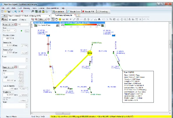
Figure 80 Pipe Flow Expert interface in Results mode ... 164
Figure 81 Results Tables ... 164
Figure 82 PDF Report Options Dialog ... 165
Figure 83 PDF Report Pages ... 166
Figure 84 Configuration Options dialog – Labelling tab ... 167
Figure 85 Configuration Options Screen – Units tab ... 168
Figure 86 Results Tables – All Results tab ... 169
Figure 87 Save Results as Excel File dialog ... 170
Figure 88 pipe system results in Microsoft Excel ... 171
Figure 89 Create PDF Report Options ... 172
Figure 90 PDF Results Report Pages ... 173
Figure 91 Hydraulic Grade Line ... 178
Figure 92 Flow balance at a join point ... 179
Figure 93 Pressure balance around a loop ... 179
Figure 94 Pseudo Loop ... 179
Figure 95 Flow Control Valve replacement ... 188
Figure 96 Pressure Reducing Valve replacement ... 189
Figure 97 Back Pressure Valve replacement... 190
Figure 98 Fixed Flow Rate Pump replacement... 191
Introduction
Pipe Flow Expert is a software application that runs on the Microsoft Windows operating system. It used by engineers in over 75 countries worldwide, to model pipe systems where the flow rates, pressure losses, and pumping requirements of the system need to be calculated.
The Pipe Flow Expert software has an intuitive interface that makes it easy for users to start working on their pipe designs, which can be drawn out on a 2D or 3D isometric grid.
The software is backed up by an unrivalled support service that provides help to users when they need it.
Pipe Flow Expert Software
Pipe Flow Expert is designed to help today’s engineers analyze and solve a wide range of hydraulic problems where the flow rates, pressure losses and pumping requirements throughout a pipe network must be determined.
The Pipe Flow Expert software will allow you to easily draw out a pipeline system and analyze the performance of the system when flow is occurring. Pipe Flow Expert calculates the balanced steady flow and pressure conditions of the system.
The software will allow you to perform analysis of alternate systems under various operating conditions.
The reported results include:
flow rates for each pipe
fluid velocities for each pipe
Reynolds numbers
friction factors
friction pressure losses
fitting pressures losses
component pressure losses
pressures at each node
HGL (hydraulic grade line) values
pump operating points
NPSHa at pump inlet
The input and display of system information on the Pipe Flow Expert drawing and in the results tables can be shown in metric or imperial units to suit your preference and specific units for each item (such as flow rate) can also be configured and set on an individual basis as required. The Pipe Flow Expert software has been designed for the professional engineer who needs a powerful tool that has a class leading, easy to use and robust interface that makes it simple to design and analyze pipe networks.
Pipe Flow Expert Software Overview
Pipeline systems range from very simple ones with a single pipe to very large and complex networks with hundreds of interconnecting pipes. They may be as simple as a single pipe carrying water from one reservoir to another reservoir, or they may be more complex with many pipelines interconnecting to distribute fluid over a large area, or they could fall somewhere in-between such as a system that transfers a chemical from a supply container to various process points.
The pipelines may vary in size and nature and will usually involve changes in elevation from one point to another. These pipeline systems may include reservoirs, pressurized tanks, pumps, valves, flow control devices, heat exchangers and other components that affect flow in the pipelines. The pipeline system is modeled by drawing the join points and the connecting pipes on a drawing pane. Horizontal, vertical or sloping lines can be used to connect one node to another node. The physical data describing the system is entered by the user and typically includes:
The internal size, internal roughness and length of each connecting pipe
The elevation of each join point (node)
The In-flow and the Out-flow at each join point (if applicable)
The elevation, liquid level and surface pressure data for each tank
The performance data for each pump
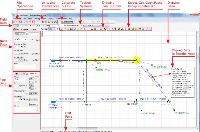
Data input boxes are located at the left hand side of the drawing pane. These input boxes will display the data for the currently selected node or pipe and may be used to amend the current data. The data for a node, pipe, pump, etc. can be amended at any point during the design process.
Once the design has been completed, the system can be analyzed and the flow and pressure results can be calculated. For liquid systems, the pressure losses within the system are calculated using friction factors obtained from the Colebrook-White equation, and the pressure loss due to friction in each pipe is obtained from the Darcy-Weisbach equation. For gas systems, the pressure losses are calculated using a compressible isothermal flow equations such as the General Flow Equation. An initial approximate solution is obtained using Linear Theory methods and an iterative approach that adjusts the flow rates until an approximate pressure balance is achieved. The solution is then converged to an accurate solution using sophisticated matrix techniques and other iterative algorithms.
Pipe Flow Expert defines the elements of the pipeline system in a series of mathematical equations. Pipe systems can produce a highly non-linear set of equations that are difficult to solve. The Pipe Flow Expert software uses the Newton method and other proprietary algorithms to solve the equations, to determine the flow rate and pressure loss in each pipe that provides a balanced solution.
The results of the flow rates for each pipe, the fluid velocities for each pipe, Reynolds numbers, friction factors, friction pressure losses for each pipe, fittings pressure losses, pressure at join points (nodes), HGLs (hydraulic grade line), pump operating points and more can be viewed on the results drawing and on the results grid.
Minimum Operating System Requirements
Pipe Flow Expert has been designed to work on the following operating systems: Microsoft® Windows 10 (All Versions)
Microsoft® Windows 8 (all versions except RT [used on ARM based tablets] )
Microsoft® Windows 7 (all versions)
We recommended using one of the above operating systems, however the software will also run on:
Microsoft® Windows Vista (all versions)
Microsoft® Windows XP (all versions)
It is recommended that your computer system has at least the following minimum specification:
Processor: 1.00 GHz or faster CPU
Memory (RAM): 2Gb or higher
Screen Display: 1024 x 768 pixels (minimum resolution) 1920 x 1080 pixels (or higher recommended)
Graphics (RAM): 128 Mb or higher
Hard Disk: 60 Mb install (250 Mb free space recommended)
Microsoft® Excel is required if the user wishes to export the results tables to a spreadsheet format.
Adobe® Acrobat Reader is required if the user wishes to generate and view customized PDF Reports based on the calculated results data.
Note:
Registration and Licensing Information
Pipe Flow Expert is a software package that is provided for use on personal computer systems.
Installation
When the software is installed it generates a unique product number that is shown on the Software License screen when you run the program. A matching license code must be entered to fully enable and license the software.
Figure 1 Pipe Flow Expert License Software
Purchasing a License
Each installation of the Pipe Flow Expert software requires a license code to be entered in order to fully activate the program. Until the license code is entered the software can only be used in trial mode.
License codes can be purchased fromwww.PipeFlow.com
Standard licensing and pricing options are shown on the web site at www.pipeflow.com.
You do not require an internet connection when licensing and enabling the software. The software does not need an internet connection to operate.
Moving a License
We allow a user to move the license to another machine. The old license is de-activated which generates a License Removal Confirmation Number. We then provide a new license code for a new installation of the software. This service is provided at no further cost as part of the Annual License fee which also includes support.
Network Licensing
The software can be operated over a network and used by a number of concurrent users. Network installation is simple and only requires that the software is installed to a shared network drive. Each user then runs the program as normal from the shared drive. When licensing the program you will need to purchase a software license that supports the maximum number of concurrent users that you require.
Please email [email protected] with your network licensing requirements to obtain a competitive quote for your specific needs.
Software Distribution Note
All of our software is provided via download from our web sites at www.pipeflow.com and www.pipeflow.co.uk
We do not provide the software on CD, since it would be exactly the same as the program that can be downloaded from our web site. This helps to reduce our costs, which allows us to offer lower prices for our customers and also guarantees that the user is always installing the latest version of the software. Users are free to make their own CD copy of the software, however every installation of the program will generate a new product code and a new license code will still be required.
New Customers
Those of you who have previously purchased software from us will already be assured of our reputation and will not be concerned about receiving the software via download. However we understand that as a new customer you may be concerned that you do not get a CD with the software on.
If we provided the software on CD it would be the exact same program that you can download from our web site (in fact the web site will always carry the very latest version of the software). Having a CD would not allow you to install and enable the software on multiple computers, since each
installation would still generate a unique product number and would require a matching license code. When you purchase a program from our web site, you will automatically be emailed with a unique purchase token and an invoice/receipt that confirms your purchase. This is all you need for proof of purchase and we will always be able to confirm your purchase in our database.
We have sold software via download for over 15 years. We are not one of those companies who you will not be able to contact or get a response from. As our existing customers know, our service and assistance with any issues you may have is worth far more than just having the software on CD. We do sell a license to use a copy of the Pipe Flow Expert software on a USB drive. When this option is purchased, we send you a ‘Pipe Flow’ branded USB drive and allow you to license this. This provides a completely portable copy of the software. There is nothing to install. The USB drive can be plugged in to any Windows based computer and the Pipe Flow Expert software can then be run directly from the USB drive, up into the memory of the local computer.
The Pipe Flow Expert software can be downloaded and installed for a free trial.
A license code can be purchased from our web site at www.pipeflow.com that will enable use of the software for an initial period of time (normally 12 months).
A user can be up and running with a licensed version of the software within a few minutes.
An Annual License fee must be paid to extend the license to use the software for a further 12 months, once the initial 12 month license period ends. The Annual License fee can be paid at www.pipeflow.com and is usually about 15% of the cost of the initial 12 month license fee.
Software support and maintenance, including technical assistance, help with modeling issues and free upgrades to new releases, are provided for free while you are running a licensed copy of the Pipe Flow Expert software. This ensures that you will always be able to use the latest version of the software.
Contacting Pipe Flow Software
Email: [email protected] Internet: http://www.pipeflow.com UK Telephone: +44 (0)1625 509142 USA Telephone: +1 650-276-3569 +1 650-276-FLOWPipeFlow.com and PipeFlow.co.uk are trading names of Daxesoft Ltd, a U.K. Registered Company)
Additional Pipe Flow Software Programs
Pipe Flow Wizard - "What if?" Calculations on a Single Pipe for Liquids and Gases
Pipe Flow Wizard is able to perform four different calculations depending on the known information. It can calculate:
Pressure Drops
Flow Rates
Size of Internal Diameters
Pipe Lengths
Pipe Flow Wizard will perform calculations for individual pipes.
Pipe Flow Wizard will calculate results for LIQUIDS or COMPRESSED GASES A Fluid Database is included with viscosity and density of common fluids.
Flow Advisor - for Channels and Tanks
Flow Advisor may be used to estimate water flow rate from various shaped channels and tanks. It can calculate:
Open Channel Flow
Water Flow Rates
Time taken to empty tanks
Volume, Capacity, Weight and Expansion
A Materials Database is included with density and coefficient of expansion of common materials. All of our software can be downloaded for a free trial by visiting www.pipeflow.com
Once you have installed a trial version of one of our software products it can be fully enabled and licensed by buying a license code from our web site. You can be up and running with a fully licensed program within just a couple of minutes
Interface and Menus
This section details the different features of the Pipe Flow Expert interface. For each feature, there is an explanation, a screen shot and a table providing descriptions for each element of the feature. The sections following this section provide instructions for using the Pipe Flow Expert application.
Figure 2 Pipe Flow Expert interface
Menu Bar
The menu bar has nine different menu selections to help you navigate and work in Pipe Flow Expert.
File Menu
Figure 4 File Menu
Menu Items Description
New Opens a new drawing grid in the Drawing pane.
New Tab Opens a new drawing grid in a new tab. Tabbed Design Sheets let you work on multiple systems simultaneously. Up to 4 different systems may be worked on concurrently using the ‘Tabbed’ system feature. Open Opens the Open dialog. Select a .pfe file and click the Open button to
open a pipe system drawing in Pipe Flow Expert.
Open Examples Opens the Example Systems screen. Select an example and click the Load This Example System button to open an example system drawing in Pipe Flow Expert.
Save As Opens the Save As dialog. Browse to where you want to save the pipe system, name the .pfe file, and click Save.
Save Screen Image Save an image of the visible drawing area as a jpeg file. Save Screen as EMF Metafile Save the drawing as an Enhanced Metafile.
Email System Opens a new email message with a .pfe file of your current design attached to an email.
Email Screen Image Opens a new e-mail message with a jpeg of the screen image attached to the e-mail.
Create PDF – System Drawing Create a PDF document of the system drawing. Create PDF – Customized
Report
Create a PDF customized report, including cover sheet with logo image, system drawing and results tables. Including a high resolution pump graph with performance curves.
Print Opens the Printing Information dialog. Type the page title and click the Print button to print the image currently visible in the Drawing pane. Page Setup Opens the Print Setup dialog. Define your printing preferences and
click OK
Import Image Opens the Import Image dialog. Allows browse of folders and files, to select import of image file on to the system drawing.
Recover from AutoSave Files Pipe Flow Expert will automatically save a backup of your current design at approximately 5 minute intervals. In the event of a problem you can try to load the most recent backup file to try and recover your system.
Purge Auto Saved Files Delete the files created by the auto save feature.
Edit Menu
Figure 5 Edit Menu
Menu Items Description
Undo The last node or pipe action performed in the Drawing pane is undone.
Redo The last undo action is redone. Cut Selected items are cut to the clipboard. Copy Selected items are copied to the clipboard.
Paste Items on the clipboard are pasted in the Drawing pane. Delete Selected item(s) are deleted.
Selection: Rotate +90 Degrees Selected items are rotated 90 degrees clockwise Selection: Rotate -90 Degrees Selected items are rotated 90 degrees anticlockwise Selection: Mirror Items Left/Right Selected items are mirrored left to right
Selection: Invert Items Up/Down Selected items are inverted up to down
Edit Grid – Sheet View Opens an edit grid allowing details of pipes, nodes and valves etc. to be amended.
Units Menu
Figure 6 Units Menu
Menu Items Description
Imperial Units Converts all values to imperial units. Metric Units Converts all values to metric units.
Specify Units Opens the Units tab of the Configurations Options dialog. Use the Units tab to define the units for each element of the pipe system drawing.
Fluid Menu
Menu Items Description
Change Fluid Opens the Fluid data dialog. Use the Fluid data dialog to define the fluid for the selected fluid zone.
Create New Fluid Zone Opens the Fluid Manager to select a fluid for a new Fluid Zone Delete Current Fluid Zone Delete the current fluid zone from the system. All pipes that previously
contained this fluid will now contain the fluid from zone 1. Change Color for this Fluid
Zone
Select a background highlight color for this fluid zone. Select / Add Pipes to this
Fluid Zone
Display the fluid zone selection rectangle. Click and drag the rectangle to enclose the pipes to be set to the current fluid zone
On / Off Show Colors for Fluid Zones
Toggle the fluid zone background highlight colors on or off.
Reset Fluid Zones to Default Colors
Drawing Menu
Figure 8 Drawing Menu
Menu Items Description
Set Standard Drawing Mode Set rectangular grid drawing mode Set Isometric Drawing Mode Set isometric grid drawing mode Isometric Tank View From Left Show isometric tanks viewed from left Isometric Tank View From Right Show isometric tanks viewed from right Mirror View (Switch Left/Right) Mirror the complete drawing
Invert View (Switch Top/Bottom) Invert the complete drawing
Change Default Pipe Values Opens the Default Values tab of the Configurations Options dialog. Use the Default Values tab to define default values for the next pipe to be drawn in the pipe system.
Choose Labelling Options Opens the Labelling tab of the Configurations Options dialog. Use the Labelling tab to define how the pipe system drawing is labelled. Zoom to Fit on Screen Resize the drawing and center in the visible drawing area
Tools Menu
Figure 9 Tools Menu
Menu Items Description
Edit Grid – Sheet View Amend data for Pipes, Tanks, End Pressures, Nodes, FCVs, PRVs, BPVs, Cv Values, Kv Values, Fixed Losses, Pumps (Fixed Flow), Pumps (Fixed Head) and Pumps (Curve).
The data in the grid may be over typed with new data – changes will be made immediately as each item of data is amended.
Options Opens the Configuration Options screen. Use the Configuration Options to configure the pipe system.
License Menu
Figure 10 License Menu
Menu Items Description
License Status Displays the current license status and registration information. View License Agreement View agreement between Licensor and Licensee
Move this License Displays instructions that explain how to deactivate the current license and obtain a license removal confirmation code. How to create a new installation (which will require a new license code).
Documentation Menu
Figure 11 Documentation Menu
Menu Items Description
Open Quick Start Guide PDF Open the Quick Start Guide PDF document Open User Guide PDF Open the full User Guide PDF document Open Non-Compressible
Results Verification PDF
Open the Non-Compressible (Liquids) Calculation Results Verification PDF document
Open Compressible Results Verification PDF
Open the Compressible (Gases) Calculations Results Verification PDF document
Open Compressible Flow Equations PDF
Open the Compressible Flow Equations & formula descriptions PDF
Help Menu
Figure 12 Help Menu
Menu Items Description
Contents Displays the Help information starting at the contents page. Index Displays the Help information starting at the index page.
Load Example Systems Lists the examples systems that can be loaded, viewed, and the results calculated.
Create a System – Step by Step
Displays the Help information starting at the page that describes how to create a system using a step by step walkthrough of each operation. License Status Displays the current license status and registration information. Move This License Displays instructions that explain how to deactivate the current license
and obtain a license removal confirmation code. How to create a new installation (which will require a new license code).
Go to www.pipeflow.com Launches an internet browser window to view the Pipe Flow web site. About Pipe Flow Expert Displays a pop-up window that shows details about the software.
Tool Bar
Most of the Pipe Flow Expert functions can be performed by using a button on the tool bar. The Re-Design, Results Sheet, Results PDF and Show Log buttons are only available on the tool bar after you click the Calculate button on the tool bar.
The tool bar also contains a field for determining whether the unit values displayed in Pipe Flow Expert and the pipe system are imperial or metric. The first step in creating a pipe system is to select the Imperial or Metric option. You can define whether imperial or metric values are used from the tool bar, the Units menu, or from the Units tab in the Configuration Options dialog. Inches, feet, and gallons are examples of imperial units. Centimeters, meters, and liters are examples of metric units.
Tool Bar Buttons
Button Name and Description
New Grid – Opens a new drawing grid.
Open File – Opens the Open dialog. Select a .pfe file and click the Open button to open an existing pipe system drawing in Pipe Flow Expert.
Save File – Saves your changes to the pipe system drawing.
Email System Information – Opens a new e-mail message with the pipe system .pfe file attached to the e-mail.
Email Screen Image – Opens a new e-mail message with a jpeg of the screen image attached to the e-mail.
Print – Opens the Printing Information dialog. Type the page title and click the Print button to print the image currently visible in the Drawing pane.
Create PDF of System Drawing – Produces a high resolution PDF of the system drawing including items which may be currently off-screen.
Toggle Isometric Grid – Switch to Isometric Drawing Grid, or back to Standard Grid. Network Grid View – Opens a grid to display details of pipes, tanks, end pressures and nodes. The data displayed in the grid may be edited to change the network data. Any changes are applied immediately to the drawing.
Set Pipe Default Drawing Values – Opens the Pipe Settings tab of the Configurations Options dialog. Use the Pipe Settings tab to define the pipe default values for drawing or to copy some of the pipe attributes to selected pipes in the system.
Choose Labelling – Opens the Labelling tab of the Configurations Options dialog. Use the Labelling tab to define how the pipe system is labelled in the Drawing pane.
Choose Units – Opens the Units tab of the Configurations Options dialog. Use the Units tab to define the units for each element of the pipe system.
Calculation Settings – Opens the Calculations tab of the Configurations Options dialog. Use the Calculations tab to select method of solution and method of calculation, and set calculation parameters.
The Hint pane displays tips for using the button currently selected on the tool bar. The Hint pane displays tips for the following buttons:
In Results mode the Hint pane is used to display information about the flow rates in pipes, velocities in pipes, pressure drop in pipes, pressures at join points, HGL (hydraulic grade line), elevations of tanks and nodes, and fluid heads in the pipeline system. Items are highlighted by clicking on an item in the drawing pane. Data for the highlighted item is displayed in the hint pane.
Fluid – Opens the Fluid menu, select change fluid to open the Fluid data dialog. Use the Fluid data dialog to define the fluid for the currently selected fluid zone. Select other fluid menu options to change the fluid zone color or to create a new fluid zone or to delete a fluid zone.
Zoom Out – Moves the focus of the pipe system out to see more of the drawing at a reduced size in the Drawing pane.
Zoom In – Moves the focus of the pipe system in to get a close-up view in the Drawing pane.
Move to Centre of Grid – Centers the pipe system on the drawing grid.
Show Item Info – Select the show information cursor. Click an item in the Drawing pane to display its details in the Node pane, Pipe pane, or dialog associated with the selected component.
Pan the Drawing – Select the move grid cursor. Click in the Drawing pane, and while holding down the left mouse button, move the mouse to pan the drawing.
Drag and Move Items – Highlights all items on the drawing. Select a highlighted object, and while holding down the left mouse button, drag the object to its new position.
Add Tank – Select the tank cursor. Click where you want to add a tank in the Drawing pane. Use the Node pane to enter the Elevation, Liquid level and Fluid surface pressure for the tank.
Add Demand (Pressure) – Select the end pressure cursor. Click where you want to add a fixed pressure demand in the Drawing pane. Use the Node pane to enter the pressure and elevation for this fixed pressure demand.
Add Join Point – Select the join point (node) cursor. Click where you want to add a pipe join point in the Drawing pane.
Add Pipes – Select the draw pipes cursor. Click on a node in the Drawing pane where you want to add a pipe, and then click where you want the pipe to end. Right-click to turn off the rubber banding.
Add Fittings – Select the valve and fittings cursor. Click on the pipe on which you want to add valves or fittings. Use the Pipe fittings friction coefficients dialog to select the valves or fitting to be added.
Add Component Pressure Loss – Select the component cursor. Click on the pipe on which you want to add a component. Use the Component pressure loss dialog to enter the pressure loss characteristics of the component.
add a control valve. Use the Control data dialog to choose a flow valve type. Choose a Flow Control Valve (FCV) to set the flow rate required in the pipe, or a Pressure Reducing Valve (PRV) to set the pressure required at the end of the pipe, or a Back Pressure Valve (BPV) to set the pressure required at the start of the pipe.
Add Pump – Select the pump cursor. Click on the pipe on which you want to add a pump. Use the Pump data dialog to enter the pump performance characteristics.
Add Demand (Flow) – Select the add demand flow cursor. Click on a node in the Drawing pane where you want to set a demand flow. Use the Flow demands dialog to set the In-flows or Out-In-flows at the selected node.
Toggle to Open/Close a Pipe – Select the open/close pipe cursor. Click on a pipe in the Drawing pane where you want to close a pipe or to re-open a pipe that has been closed previously.
Add Text – Add Free text labels to the drawing.
Selection Tool – Select the selection rectangle cursor. Click in the Drawing pane, and while holding down the left mouse button, drag the mouse to create a rectangle around the item(s) you want to select for cutting, copying, pasting, deleting or moving. You can select multiple items to cut, copy, paste, delete or move as a group. Click the right mouse button to exit from selection mode.
Cut – Selected items are cut to the clipboard. Copy – Selected items are copied to the clipboard.
Paste – Items on the clipboard are pasted in the Drawing pane. Mirror – Selected items are mirrored left / right.
Invert – Selected items are inverted up / down.
Zoom Selected Area – Displays the selection area in a close-up view in the centre of the Drawing pane.
Select Individual Pipes and Nodes – Use the Adjust attributes of Selected Pipes tool button to display the Pipe Settings tab to make changes to all selected pipes.
Use the Adjust attributes of Selected Nodes tool button to display the Node Settings tab to make changes to all selected nodes.
Adjust Attributes of Selected Pipes – Opens the Pipe Settings tab of the Configurations Options dialog. Use the Pipe Settings tab to copy various attributes of the default pipe to each of the pipes selected. The Selection Tool may be used to Select a group of pipes prior to opening the Pipe Settings tab. Individual pipes can be added or removed from the selected list by checking or un-checking the box adjacent to the pipe description. Adjust Attributes of Selected Nodes – Opens the Node Updates tab of the
Configurations Options dialog. Use the Node Updates tab to copy node elevation and images to each of the nodes selected. The Selection Tool may be used to Select a group of nodes prior to opening the Node Updates tab. Individual nodes can be added or removed from the selected list by checking or un-checking the box adjacent to the node description. Delete – Selected item(s) are deleted. If a selected item is a node then all pipes which connect to the node will also be deleted.
Undo last action – The last add pipe or node action performed in the Drawing pane is undone.
Redo last undo action – The last undo action is redone.
Calculate – Calculates the flow and pressure at each node of the pipe system drawing. The calculation results are displayed on the Results window.
Re Design – Changes the view back to the design mode. The pipe system is displayed in drawing mode again. This button is only visible on the tool bar after clicking the Calculate button.
Results – Opens the Results window. This button is only visible on the tool bar after clicking the Calculate button.
Results PDF – Opens the Results PDF dialog. Add a logo, chose the options required and produce a PDF of the results, including a system image and pump graphs. This button is only visible on the tool bar after clicking the Calculate button.
Show Log – Opens the Results Log dialog. The Results Log dialog indicates whether the pipe system was solved. This button is only visible on the tool bar after clicking the Calculate button.
Example Systems – Opens the Example Systems dialog. Over 40 examples systems are provided to illustrate usage of the Pipe Flow Expert software. This button is only visible on the tool bar if design mode is selected.
Next Example – Loads the Next Example System from the examples systems dialog. This button is only visible on the tool bar if design mode is selected.
New Tab – Opens a new design sheet allowing users to work on multiple systems simultaneously. Tabbed Sheets work in both Design View and Results Mode. Switch between different system models with a single click
Keyboard Shortcuts
Various keyboard shortcuts are provided which duplicate the actions of some Menu system options and some of the Tool Bar buttons.
CTRL+N, for New Tab
CTRL+X, for Cut
CTRL-C, for Copy
CTRL-V for Paste
CTRL-DEL key for delete operations.
CTRL+O for Open.
CTRL+S for Save.
CTRL+P for Print.
CTRL+ALT+O for Open Examples.
CTRL+R for Rotate +90 Degrees
CTRL+ALT+R for Rotate -90 Degrees
CTRL+M for Mirror Items Left/Right.
CTRL+I for Invert Items Up/Down.
CTRL+Z for Zoom to fit on screen
Node Pane
The Node pane displays the properties of the node selected on the pipe system in the Drawing pane. The type of node selected in the Type field determines which features are available in the Node pane.
Node Types
A node can be a join point, tank, or demand pressure–referred to as End Pressure in the Node pane. The type of node selected is shown in the Type field. The type of node can be changed by selecting from the options shown in drop down type list.
Nodes are located at the beginning and end of a pipe and at the junction of pipes in a pipe system. You can use the drop down Node Id list next to the Node name field to select an individual node or to scroll through each of the nodes in the pipe system.
Click the zoom button next to the drop down Node Id list to redisplay the drawing with the selected node at the center of the visible drawing area.
The Node pane is also used to enter and edit the specific details for the selected node. The values and units displayed in the node pane are determined by the units selected on the Units tab in the Configuration Options dialog. The selected units can also be switched on mass between a predefined set of imperial and metric units.
Tank Node Data
Figure 13 Tank Node Pane
Feature Description
Node The name of the node currently selected in the Drawing pane. Use the Node field to edit the node name.
Node Id List Use the Node Drop Down List to select a node or to scroll through each of the nodes in the pipe system.
Type (Tank) The type of node currently selected in the Drawing pane. Use the Type field to modify the node type. There are three types of nodes – join point, tank, or fixed pressure demand (End Pressure).
Type (Tank Icon) Displays the image representing the selected tank in the Drawing pane. Use the Icon button to select the tank image you want displayed on the pipe system drawing.
The icon size can be selected from a range of scales. The image you select does not affect any of the tank’s properties or values.
Surface Pressure The surface pressure of the fluid in the tank expressed in the units displayed.
Liquid Level The amount of fluid above the tank exit point expressed in the units displayed.
Elevation (Exit from tank) The elevation at the exit point of the tank expressed in the units displayed.
Notes Notes about the node currently selected in the Drawing pane. Notes can be up to 200 characters.
End Pressure Data
Figure 14 End Pressure Node Pane
Feature Description
Node The name of the node currently selected in the Drawing pane. Use the Node field to edit the node name.
Node Id List Use the Node Drop Down List to select a node or to scroll through each of the nodes in the pipe system.
Type (End Pressure) The type of node currently selected in the Drawing pane. Use the Type field to modify the node type. There are three types of nodes – join point, tank, or demand pressure (End Pressure).
Type (End Pressure Icon) Displays the image representing the selected demand pressure in the Drawing pane. Use the Icon button to select the end pressure image you want displayed on the pipe system drawing.
The icon size can be selected from a range of scales. The image you select does not affect any of the demand pressure’s properties or values.
Pressure The required pressure for the end pressure expressed in the units displayed.
Elevation (of Pressure Point) The elevation of the end pressure expressed in the units displayed. Notes Notes about the node currently selected in the Drawing pane. Notes can
Join Point Data
Figure 15 Join Point Node Pane
Feature Description
Node Identification Number
Use the Node Drop Down List to select a node or to scroll through each of the nodes in the pipe system.
Node The name of the node currently selected in the Drawing pane. Use the Node field to edit the node name.
Type (Join Point) The type of node currently selected in the Drawing pane. Use the Type field to modify the node type. There are three types of nodes – join point, tank, or demand pressure (End Pressure).
Type (Join Point) Icon Displays the image representing the join point in the Drawing pane. Use the Icon button to select the join point image you want displayed on the pipe system drawing.
The icon size can be selected from a range of scales. The image you select does not affect any of the joint point properties or values.
Elevation of Join Point The elevation of the join point expressed in the units displayed. Demands In (at Join Point) View the In Flow to the system at this node. Click edit to change. Demands Out (at Join Point) View the Out Flow from the system at this node. Click edit to change. Edit buttons (Join Point) Opens the Set Flow Demands dialog. This dialog is used to set a demand
flow on the join point.
Notes Notes about the node currently selected in the Drawing pane. Notes can be up to 200 characters.
Flow Demands
Flow demands can only be added at a node if the type selected is a Join Point.
Figure 16 Flow Demands
Feature Description
In Flow Rate Entering The System
The flow rate entering the system at this node expressed in the units displayed.
Out Flow Rate Leaving The System
The flow rate leaving the system at this node expressed in the units displayed.
OK Confirm any changes that have been made. Cancel Close the dialog without making any changes.
Pipe Pane
A pipe can have many features, such as name, length, internal diameter, roughness, nominal size, material, schedule or class reference, internal volume and surface area.
The data for some of these features, such as name, length, internal diameter and roughness can be entered directly into the pipe pane input boxes (other features would be left unchanged and may have to be amended at a later time).
To set all the features of a pipe use the Diameter and Material buttons to access the selection dialogs.
Pipe Flow Expert allows fittings and valves, components, flow control valves and pumps to be added to a pipe. The selection dialogs to add or change the data for these items can be accessed by clicking on the appropriate button in the pipe pane.
Pipe Features
Figure 17 Pipe Pane and Pipe Sub-menu
Feature Description
Pipe Identification Number Use the Pipe Drop Down List to select a pipe or to scroll through each of the pipes in the pipe system.
Name The name of the pipe currently selected in the Drawing pane. Use the Name field to edit the pipe name.
Length The length of the pipe currently selected in the Drawing pane. Use the length field to change the length of the pipe.
Internal Diameter The internal diameter of the pipe currently selected in the Drawing pane. Use the internal diameter field to change the internal size of the pipe. Click the Diam? button to display the Pipe Diameter Database sizes. Roughness The internal roughness of the pipe currently selected in the Drawing
pane. Use the roughness field to change the internal roughness of the pipe. Click the Material button to display the Pipe Material Database. Notes Notes about the pipe currently selected in the Drawing pane. Notes can
be up to 200 characters.
Pipe Color and Line Width Set the color and line width of the pipe currently selected in the Drawing pane.
Add/Change Fittings button Opens the Pipe fitting friction coefficients database. Use the database to add and maintain fittings on a pipe. The number of fittings on the pipe is displayed next to the fitting image on the Add/Change Fitting button.
Add/Change Component Pressure Loss button
Add a component to the pipe currently selected in the drawing pane. Change the Pressure Loss characteristics for the component. A number is displayed next to the Component image to indicate if the component is active.
Add/Change Control Valve button
Add a control valve to the pipe currently selected in the drawing pane. Set the maximum flow rate in the pipe by using a flow Control Valve (FCV), or set the pressure at the end of the pipe by using a Pressure Reducing Valve (PRV), or set the pressure at the start of the pipe by using a Back Pressure Valve (BPV). A number is displayed next to the Control Valve image to indicate if the Control Valve is active.
Add/Change Pump button Add a pump to the pipe currently selected in the Drawing pane. Enter the flow rate and head characteristics for various points on the pump performance curve. A number is displayed next to the Pump image to indicate if the Pump is active.
Include check boxes Include/Exclude status for various items added to the pipe currently selected in the Drawing pane.
i.e. Fittings & Valves, Components, Control Valves, Pumps.
Diam? Display the Pipe Diameter Size Database. A Double Click on a pipe will also display the Pipe Diameter Size Database.
Material Display the Pipe Material Database.
More…. Opens the pipe sub menu which provides further options to:
Re-Open / Close Pipe
Reverse Pipe Direction
Prevent Backflow – On / Off
Move / Unlink end of Pipe
Use Pipe Values for as default for the next pipe to be drawn
Change Fluid Zone (for pipe)
Close sub menu
Pipe Material Data
Figure 18 Pipe Material Data
Feature Description
Material The material description of the pipe currently selected in the Drawing pane. Schedule/Class The Schedule/Class description of the pipe currently selected in the
Drawing pane.
Internal Roughness The internal roughness of the pipe currently selected in the Drawing pane. Nominal Size The Nominal Size description of the pipe currently selected in the Drawing
pane.
Internal Diam. The internal diameter of the pipe currently selected in the Drawing pane. Wall Thick The wall thickness of the pipe currently selected in the Drawing pane. Outside Diam The outside diameter of the pipe currently selected in the Drawing pane. Weight The weight per unit length of the pipe currently selected in the Drawing
pane.
Internal Vol. The internal volume (ft³/100 ft or m³/100m) of the pipe currently selected in the Drawing pane.
Surface Area The external surface area (ft²/100 ft or m²/100m) of the pipe currently selected in the Drawing pane.
Save Pipe This button is not available during pipe material selection. Cancel (Changes) This button is not available during pipe material selection.
Change Material Show Listing of available pipe data materials. Select Show size data for selected material. Cancel Revert to previously selected size listing.
Add New Material Create a new material category to which new pipe sizes can be added. Remove Material Remove a material category.
Pipe Diameter Data
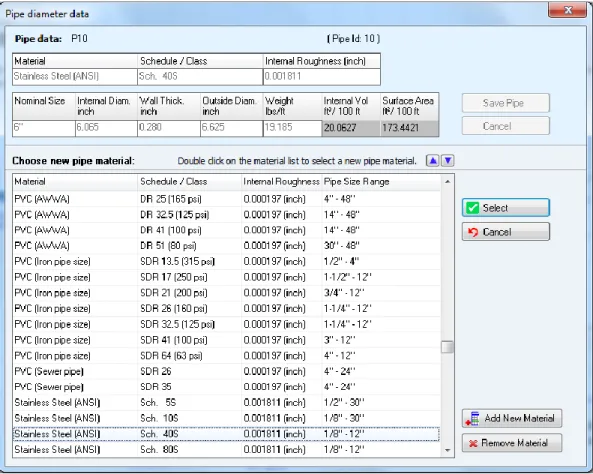
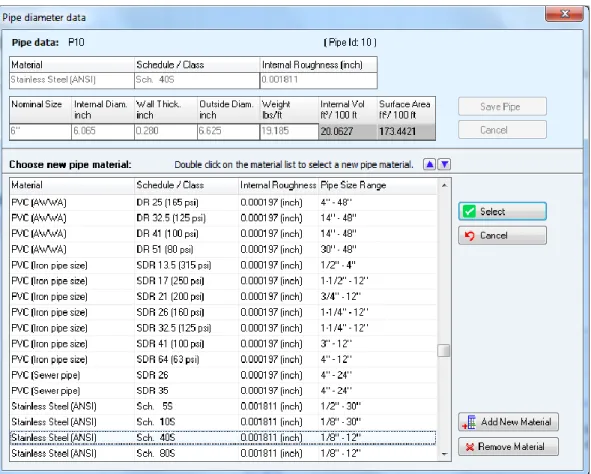
Figure 19 Pipe Diameter Data
Feature Description
Material The material description of the pipe currently selected in the drawing pane.
Schedule/Class The Schedule/Class description of the pipe currently selected in the drawing pane.
Internal Roughness The internal roughness of the pipe currently selected in the drawing pane.
Nominal Size The Nominal Size description of the pipe currently selected in the drawing pane.
Internal Diam. The internal diameter of the pipe currently selected in the drawing pane. Wall Thick The wall thickness of the pipe currently selected in the drawing pane. Outside Diam The outside diameter of the pipe currently selected in the drawing pane. Weight The weight per unit length of the pipe currently selected in the drawing
pane
Internal Vol. The internal volume (ft³/100 ft or m³/100m) of the pipe currently selected in the drawing pane.
Surface Area The external surface area (ft²/100 ft or m²/100m) of the pipe currently selected in the drawing pane.
Save Pipe Save the selected data to the pipe currently selected in the drawing pane.
Cancel Close the Pipe Diameter database without making any changes. Transfer Selected Size Copy size data from data listing to entry boxes (at top of the screen). Size data listing Listing of pipe sizes.
Metric or Imperial Display size data in metric or imperial units. Change Material Display data dialog for pipe material. Add new size Display input boxes for new pipe size data. Remove entry Remove a pipe size.
Pipe Fittings Database
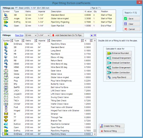
Figure 20 Pipe Fittings Database
Feature Description
Symbol Fitting type symbol. Type Fitting type short code. Metric Nominal metric fitting size. Imperial Nominal imperial fitting size. Description Fitting description.
K value Local loss coefficient of fitting.
Qty Quantity of fittings.
Position Fitting position. Define to be at Start or End of pipe.
Save Save the fitting selections to the pipe currently selected in the drawing pane.
Clear Clear the fitting selections.
Pipe Size Click to display fittings to match the current pipe size.
Metric Pipe Sizes (mm) Drop down list of metric pipe sizes, click to display matching fitting sizes. Imperial Pipe Sizes (inch) Drop down list of imperial pipe sizes, click to display matching fitting
sizes.
Fitting Database Listing of fittings and friction coefficients.
Add Selected Item On To Pipe Copy fitting data from listing to the list on the currently selected pipe. Calculate K value Calculate local loss coefficient for: entrance rounded, gradual
enlargement, gradual contraction, sudden enlargement, sudden contraction or long pipe bend.
Create new fitting Create data for non standard fittings. Remove entry Remove data from fittings database.
Component Pressure Loss
Figure 21 Component Pressure Loss
Feature Description
Component Name Name of the component.
Pressure Loss Scroll buttons Choose symbol for the component. Fixed Loss Pressure loss will be fixed.
Curve Loss Pressure loss will be calculated from component flow / head data. Flow Flow rate values for operating range of component.
Pressure Loss Pressure loss for each of the flow rate entries.
Generate Curve Create a set of curve points from first three data points. Cv Flow Coefficient Value Model pressure loss through a valve with a Cv flow coefficient Kv Flow Coefficient Value Model pressure loss through a valve with a Kv flow coefficient
Sprinkler K (imperial) Model pressure loss using a Sprinkler K value based on flow in US gpm Sprinkler K (metric) Model pressure loss using a Sprinkler K value based on flow in l/min OK Add the component to the pipe currently selected in the Drawing pane. Cancel Close the dialog without making any changes.
Clear Clear the pressure loss data.
Delete Remove the component from the pipe currently selected in the drawing pane.
Save To File Save the component details to a file. Load From File Load the component details from a file.
Control Valve Data
Figure 22 Control Valve Data
Feature Description
Control Name Name of the control valve or P&ID number. Flow Control Valve Set control flow rate in the units displayed. Pressure Reducing Valve Set pressure required at the end of the pipe. Back Pressure Valve Set back pressure required at the start of the pipe.
Specify Allowable dP Range Set allowable dP Range, a warning will be issued if the actual dP is outside the lower and upper values.
OK Add the control valve type to the pipe currently selected in the Drawing pane.
Cancel Close the dialog without making any changes.
Delete Remove the control valve from the pipe currently selected in the Drawing pane.
Pump Data
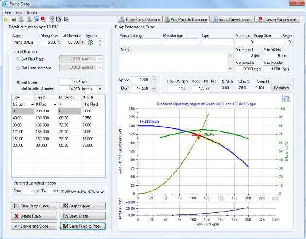
Figure 23 Pump Data
The main features of the pump data dialog are listed in the table below. The pump section later in this document provides further details of the Graph Options, the Pump Data Menu options and the options for opening the Pump Database, adding a pump to the Pump Database, Import of a Curve Image and creating a Pump Data Sheet.
Feature Description
Name Name of the pump.
Distance Along Pipe Location of the pump from start of the pipe currently selected in the drawing pane.
at Elevation Elevation of the pump. Pump Scroll buttons Choose symbol for the pump.
Set Flow Rate Enter flow rate to model a pump with a fixed flow rate
Set Head Increase Enter a head or pressure to model the additional motive force from a pump
Set Speed (rpm) Operating speed of a pump with a performance curve. Set Impeller Diameter Set impeller diameter size & units
Flow Flow rate values for operating range of pump. Displayed in units selected from drop down list.
Head Head generated for each of the flow rate entries. Displayed in units selected from drop down list.
Efficiency Efficiency of the pump at each of the operating data points.
NPSHr The Net Positive Suction Head requirement at the inlet of the pump for the flow rate value.
From (% of BEP) Start of preferred operating region. To (% of BEP) End of preferred operating region. Clear Pump Curve Clear the pump data.
Delete Pump Remove the pump from the pipe currently selected in the drawing pane. Cancel and Close Close the dialog without saving any changes
Graph Options Opens additional graph options customization dialog. Allows creation of additional data curves and adjustment of Iso efficiency lines.
See later section about Pumps for further details. Draw Graph Draw a pump graph based on entered data points.
Save Pump to Pipe Add the pump to the pipe currently selected in the drawing pane. Pump Catalog The name of the pump catalog.
Manufacturer The name of the pump manufacturer.
Type The type of pump.
Motor rpm The motor speed. Pump Size The pump size reference. Stages The number of pump stages.
Notes Notes about the pump. Notes can be up to 200 characters. Min Speed The minimum operating speed of the pump.
Max Speed The maximum operating speed of the pump. Min Impeller The minimum impeller diameter for the pump. Max Impeller The maximum impeller diameter for the pump.
Speed (rpm) Operating speed of the pump impellor diameter for the duty curve. Diam The diameter of the pump impeller, in the units shown.
Flow The flow rate of the pump duty point, in the units shown.
Head The head produced by the pump at the duty point, in the units shown. NPSHr The Net Positive Suction Head requirement at the inlet of the pump for
the flow rate at the duty point. Effic. % The pump efficiency at the duty point. Power The shaft power required at the duty point.
Calculate (Button) Click to calculate the duty point details for an entered flow rate or head requirement.
Logo (Button) Add a logo to the pump graph image Expand (Button) Expand graph to show in full window
Figure 24 Drawing Panes Standard or Isometric
Feature Description
Drawing Grid The drawing grid shows details of the pipeline system. The information to be displayed, such as size, length, elevation, flow rate etc. can be selected from the configuration options labelling tab.
Hint Feature The Hint pane, located above the tool bar, displays tips for using the button currently selected on the tool bar.
Zoom Feature If your mouse is suitable the drawing size can be zoomed larger or smaller using the mouse scroll wheel.
Drawing Size Display The drawing size can be selected from the drop down listing between the Zoom Out and the Zoom In buttons.
Zoom Out Button Click to make the drawing size smaller by one step. Zoom In Button Click to make the drawing size larger by one step. Zoom drawing to fit on screen Click to fit all of the drawing on the screen.
Pipe Flow Expert offers a choice of a drawing grid with square increments for standard designs or an isometric grid for use where it is desirable to create an isometric view.
It is possible to toggle between standard / isometric design grids.
Moving from a standard grid to an isometric grid transposes the standard drawing on to a flat isometric plane. A user can then adjust/move the nodes as necessary to produce a drawing that looks 3D.
Moving from an isometric grid to a standard grid transposes the isometric drawing to a flattened view that produces a near plan view (except that PipeFlow Expert does not allow nodes to appear at the same point on the grid and therefore nodes directly above or below each other on the isometric grid are offset at a diagonal angle when transposed to the flat view).
Configuration Options Screen
Pipe Flow Expert can be configured to suit your requirements. Labels: The labels that are shown on the drawing can be chosen.
Units: The units in which to display lengths, diameters, head loss, velocity etc. can be chosen.
Pipe Data: The default pipe data can be chosen. These details are used to drawany new pipes.
Pipe Data: Various default pipe attributes may be copied to a range of selected pipes.
Node Data: An elevation value and a node image may be copied to a range of selected nodes.
Results Colors: The results screen drawing can be displayed using a color gradient, to indicate the range of flow rates, fluid velocities, friction loss, hydraulic gradient line and elevations etc.
Calculations: The calculation parameters and tolerances can be changed (if necessary).