Mutual Coupling Reduction of a MIMO Antenna
using Meta-Materials
Prof. Premsai Regalla Prof. B. Karunaiah
Assistant Professor Associate Professor
Department of Electronics & Communication Engineering Department of Electronics & Communication Engineering Holy Mary Institutes of Technology & Science, Hyderabad,
India
Holy Mary Institutes of Technology & Science, Hyderabad, India
Abstract
2-D Meta material structure (2DMMS) is proposed to reduce mutual coupling of a two-element micro strip patch antenna. Structure consists of an upper T-shaped patch and two lower U-shaped patches connected with two shorted pins. The proposed 2-D Meta material has a negative permeability at 2.35-2.45 GHz band, which covers the operation band of the patch antenna array with an edge-to-edge array-element distance of 0.13λ0. Meta material is placed on substrate between two antenna elements, which has a
0.1mm vertical distance to the patch antennas. The results show that about more than 18 dB mutual coupling reduction is achieved by using the 2 DMMS without affecting the operating bandwidth and radiation characteristics. Thus, the proposed MIMO antenna with 2-D Meta material achieves an isolation improvement of 20dB in comparison of the simulated MIMO antenna without the proposed Meta material structure.
Keywords: Meta Material Structure, Mutual Coupling Reduction Technique, Microstrip Patch Antenna
________________________________________________________________________________________________________
I. INTRODUCTION
Now a day’s technology depends on small, fast and more reliable devices. One of the main goals in communication technologies is to make their systems as small as possible as long as their size with-out effecting the performance. This means employing more antennas and placing close to each other. Multiple input-Multiple output (MIMO) is an efficient technique for improving the reliability and the channel capacity in the next generation of wireless communication systems. When the space for antennas is limited, it forces strong mutual coupling between each antenna element decreases the channel capacity and radiated power. Moreover, smaller and higher data transmission devices are needed to install a MIMO antenna in a limited space. As a result, the distance between the antenna elements are becoming narrower, which will not only result in a strong mutual coupling between the array elements but also increase the spatial correlation. Additionally, the mutual coupling between antenna elements is an urgent problem, because the inter coupling will affect wireless system performance, antenna efficiency, as well as amplitude and phase errors. Patches are used as the Radiating elements of MIMO antenna. In the antennas era there are many methods which are studied to remove/reduce mutual coupling between radiating/patch elements. Several decoupling techniques between radiating elements in artificial structures which are Meta-material (MM) structures, Asymmetrical coplanar-strip (ACPs) wall and micro-strip stubs. Electromagnetic band gap (EBG), split ring resonator and trending SRR occupying less space. These are the types of MMs which act as wavelength resonators to suppress Electro-Magnetic wave propagation. The EBG (Electro-magnetic band gap) based mutual coupling reduction technique is not worth-full if the edge separation is less (<0.5λ0) why because EBG structures are not small.
For
Decoupling we can place an asymmetrical coplanar strip wall (ACPS) vertically between two patch elements, but it is not applicable when we aim for low-profile antenna. By etching the vertical ACPS wall into the ground and radiating elements is a complicated process. Micro-strip stubs acts as resonators for mutual coupling suppression. We can achieve by inserting inter-digital lines between two patches with small edge separation, but polarization purity will be degraded so it is not applicable for some cases. There are many artificial structures for improving isolations also suffer from either complicated fabrication process or large antenna edge separation. By placing Array-antenna decoupling surface (ADS) above the ground plane, it creates partial reflective electromagnetic (EM) waves to cancel the coupled waves from the adjacent radiating elements.it leads to high port isolation so ADS based decoupling techniques are not applicable for very closely spaced antennas because coupled reflective EM waves are out of control. Finally we can say ADS is suitable for high-profile.
index Meta materials using artificial lumped element loaded transmission lines in micro-strip technology. Types of Meta materials are 1. Electromagnetic Meta materials Transverse waves 2. Acoustic Meta materials Longitudinal waves 3. Seismic Meta materials - Transverse waves and Longitudinal waves. Which we cannot see is invisible. Meta material is a type of composite material having unusual electro-magnetic properties. At micro wave frequencies the invisible clock is realized so we can state Meta material applications to be realized, several goals must be achieved. When the light rays incident on the material would be bent around object, only to merge on the other side in exactly same side as they begin. Negative refractive index is an important characteristic in Meta material design and fabrication. As reverse-refraction media, these occur when both permittivity and permeability are negative. In negative index Meta materials, both permittivity and permeability are negative resulting in a negative index of refraction. Potential applications of Meta materials are diverse, remote aero-space applications, sensor detection and infrastructure monitoring, smart solar power management, public safety, high frequency battle field communication. Lenses for high gain antennas, improving ultrasonic sensors and even shielding structures from earth quakes. Theoretical concept of Meta material is a bit easy to understand but when comes to practical implementation purpose it is not that easy.
So many artificial structures were introduced but still needs deep study on it. Security concern is another serious issue. Tiny structures embedded in the Meta-material would have been smaller than the wavelength of electromagnetic waves which we want bend. It is the tall order for optical invisibility because structures scaled on Nano meters.
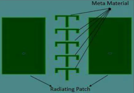
Here, a 2-Dimentional meta-material structure introduced and integrated into a two-element MIMO antenna array to reduce the mutual coupling. The designed Meta material structure consists of an upper T-shaped patch and two lower U-shaped patches, and which are connected by two shorted pins. Then, five 2-D Meta material cells are embedded into the substrate between two antenna elements, which has a vertical distance of 0.1mm from 2-D meta-material cells to the top surface of the substrate. By using the proposed meta-material structures, more than 18 dB mutual coupling reduction is achieved, which greatly enhances the isolation without affecting the operating bandwidth and radiation characteristics. The proposed structure is embedding in the FR4 substrate, which effectively reduce the profile of the MIMO array and give small effects on the bandwidth and the radiation patterns. Also, the proposed structure provides better isolation.
II.METAMATERIAL STRUCTURE & ANTENNA DESIGN CONFIGURATION
A periodic material that derives its properties from its structure rather than its components is called Meta materials.
All the scenario is explained briefly in the introduction part only. Here will focus on structure and design of antenna. Negative refractive index is the focused object in Meta materials. The configuration of the proposed two-element MIMO antenna array with developed 2-D meta-material structure is depicted in below Fig.1.a & structure of MIMO antenna array without 2-D Meta material shown in fig.1.b
Fig. 1(a): Geometry Structure of Proposed MIMO Antenna with Inserted Meta Materials
The proposed antenna is fabricated on a FR-4 substrate with a relative permittivity of εr 4.4, a loss tangent of 0.02 and a thickness
of 1.6mm. The total size of the MIMO antenna is 60 × 60mm2. Two rectangle patch antennas with 50-Ohm coaxial feeding are
utilized to construct the two-element MIMO antenna array whose edge-to-edge antenna element distance is 0.13λ0. To reduce the mutual coupling, a 2-D meta-material is developed and incorporated into the MIMO antenna. It is found that the MIMO antenna consists of two identical rectangle patch antennas fed by coaxial lines, five 2-D meta-material cells are embedded in the FR-4 substrate to improve the isolation of the MIMO antenna. The vertical distance from the upper T-shaped patch of the designed 2-D meta-material to the top surface of the FR- 4 substrate is very small. The proposed five Meta material cells are placed in between two micro strip patches.
The 2-D meta-material cell is shown in fig.1(c). It is noted that the proposed metamaterial is a non-planar structure, which is composed of an upper T-shaped patch and two lower U-shaped patches. Both of the upper and lower patches are connected via two shorted pins, which is a 2-D metamaterial structure. The proposed MIMO antenna and the 2-D meta-material are optimized by using the HFSS and the optimal parameters are: W=60, L=60, W1=15, L1=30, d1=7, d2=15, m=11, n=7.5, s=0.8, a1=6.3, a2=3, a3=2.5, a4=2.5, a5=5.2,a3=6.3mm, h=1.6, h1=0.8, h2=0.1, (unit: mm).
Fig. 1(c): Proposed Meta Material Cell
III. PERFORMANCE OF THE PROPOSED 3-D META-MATERIAL AND THE MIMO ANTENNA
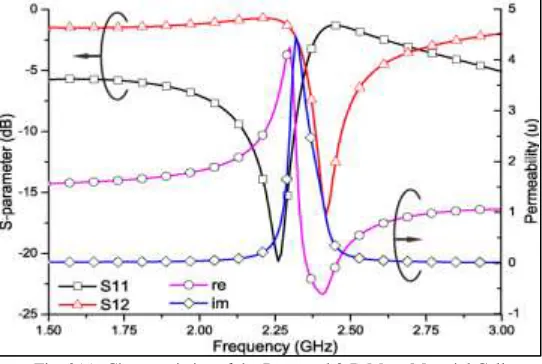
In order to master the electromagnetic properties of proposed 2-D meta-material cell, S-parameters retrieval Method is utilized to retrieve the electromagnetic Parameters of the cell. The reflection coefficient (S11) and transmission coefficient (S12) are obtained by the HFSS, which are shown in Fig.2.a. It is observed that a band-gap characteristic appears around 2.4 GHz, where the electromagnetic waves are almost reflected. Moreover, the retrieved permeability of developed 2-D meta-material cell is given in the figure We can see that the real of permeability of the 2-D metamaterial cell is negative from 2.35 GHz to 2.45 GHz, which can be used to block the surface wave propagation.
Fig. 2(a): Characteristics of the Proposed 3-D Meta-Material Cell
MIMO antenna with proposed 2-D metamaterial cells provides a significant improvement with respect to the isolation. As shown in figure iii c&d.
Fig. 3(a): Current distribution of the proposed MIMO
Antenna array at desired frequency to further understand the effects of proposed 3-D Meta-material cells in the MIMO antenna, the current distributions on the MIMO antenna are investigated and Shown in Fig.2.b at the 2.38 GHz operation band. Obviously, without the proposed 2-D meta-material structure, strong currents are coupled from one antenna to another patch antenna, whereas only weak surface currents are induced on another patch when the proposed 2-D meta-material structure is loaded. In this case, a large current appears on the proposed 2-D meta- material structure, which blocks the surface current and reduces the mutual coupling of the closed assignment MIMO antenna array.
Next, the key parameter effects on the impedance bandwidth and isolation of the MIMO antenna with respect to S11 and S21 are presented by considering a1, a3, h1 and h2. While increasing a1 value from6.1mm, it is found that the operating band of the MIMO antenna is almost constant, while the isolation is improved in terms of S12. Moreover, the S12 moves from high frequency to low frequency when a1 ranges from 6.1mm to 6.5mm. Parameter a3 has an important effect on both the bandwidth and the isolation. It says that the mutual coupling is reduce when a3 increases from 2.3mm to 2.5mm. When a3 continues to increase, both the isolation is deteriorated since the a3 changes the dimensions of the U-shaped patch and the U-shaped patch of the 2-D metamaterial cells, which alters the resonance characteristics of the meta-material. The parameter h1 and h2 affect the impedance bandwidth and the mutual coupling. When h1 increases from 0.8mm to 0.9mm, the shorted pins are increased, which increase the inductance of the 2-D meta-material. Thus, the center resonance frequency of the 2-D meta-material shifts to the high frequency and hence, the mutual coupling is also increased. The parameter h2 control the distance between the top of the 2-D meta-material and the top surface of the FR-4substrate. With the increment of h1 and h2, the 2-D metamaterial is pushed to the direction of the ground plane of the MIMO antenna, which also increases its equivalent capacitance. Thus, the center frequency and the isolation of the MIMO antenna are affected. Thus, we can optimize the parameters of the 2-D meta-material to select the proper dimensions to obtain an optimal performance.
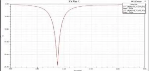
Fig. 3(b): Simulated S11 Parameter of MIMO Array Antenna with-Out 2-D Meta Material
Fig. 3(d): Simulated S11/S12 Parameter of MIMO Array Antenna with 2-D Meta Material
We find that the Envelope correlation coefficient ECC is almost zero at 2.35 GHz to 2.42 GHz, which means that the two antennas are irrelevant. Thus, our proposed 2-D meta-material structure effectively reduces the mutual coupling and helps to improve the isolation between the two antenna elements. It is found that the MIMO antenna has directional radiation patterns in both XOZ-plane and YOZ-planes. Some deviations from the measured and simulated radiation patterns arise from the errors in fabrication and experiment. The gain of the MIMO antenna array is 5 dBi in the center of the operation band.
IV. CONCLUSION
A 2-D meta-material structure has been proposed and it has been integrated into a MIMO antenna to reduce the mutual coupling between two rectangle patch antennas. The proposed D meta-material cell is a two-layer connected by the shorted pins. The 2-D meta-material cell has been investigated to catch its characteristics. Then, five 2-2-D meta-material cells have been incorporated into a MIMO antenna with a distance of 0.13λ0 to improve the isolation. Both the numerical and experimental results showed that
more than 18 dB mutual coupling reduction has been obtained without affecting the operating bandwidth and radiation characteristics. Furthermore, the proposed 2-D metamaterial structure has a flexible and adjustable characteristic, which can easily integrate into antenna array to improve the isolation.
REFERENCES
[1] Y. Li, W. Li, and R. Mittra, “Miniaturized CPWfed UWB antenna with dual frequency rejection bands using stepped impedance stub and arc shaped parasitic element,” Microwave and Optical Technology Letters, vol. 56, pp. 783-787, 2014.
[2] Y. Li, W. Li, and W. Yu, “A switchable UWB slot antenna using SIS-HSIR and SIS-SIR for multimode wireless communications applications,” Applied Computational Electromagnetics Society Journal, vol. 27, no. 4, pp. 340-351, 2012.
[3] H. Yu, G. Yang, F. Meng, and Y. Li, “Performance analysis of MIMO system with single RF link based on switched parasitic antenna,” Symmetry, vol. 9, no. 12, ID: 304, 2017.
[4] Y. Yang, Q. Chu, and C. Mao, “Multiband MIMO antenna for GSM, DCS, and LTE indoor application,” IEEE Antennas and Wireless Propagation Letters, vol. 15, pp. 1573-1576, 2016.
[5] E. Rajo-Iglesias, Ó. Quevedo-Teruel, and L. Inclán-Sánchez, “Mutual coupling reduction in patch antenna arrays by using a planar EBG structure and a multilayer dielectric substrate,” IEEE Transactions on Antennas and Propagation, vol. 56, pp. 1648-1655, 2008.