Analysis of I.C. Engine Fins for Effective Cooling
Performance
Akash M Vyas Ruchir Parikh
ME Student Assistant Professor
Department of Mechanical Engineering Department of Mechanical Engineering GIT, Ahmedabad, India GIT, Ahmedabad, India
Dr. Umang Patdiwala
Assistant Professor
Department of Mechanical Engineering Indus University, Ahmedabad, India
Abstract
When fuel is burned in an engine, heat is produced. Additional heat is also generated by friction between the moving parts. Approximately 30% of the energy released is converted into useful work while remaining 70% must be removed from the engine to surrounding, to prevent the parts from overheating. In an air-cooled I.C engine, extended surfaces called fins are provided at the periphery of engine cylinder to increase heat transfer rate. That is why the analysis of fin is important to increase the heat transfer rate. The main of aim of this work is to study different types of fins to improve heat transfer rate of cooling fins by changing cylinder fin geometry.
Keywords: Geometry of fin, Simulation of different fins, Temperature Profile of Fins
________________________________________________________________________________________________________
I. INTRODUCTION
The internal combustion engine is an engine in which the combustion of a fuel (normally a fossil fuel) occurs with an oxidizer (usually air) in a combustion chamber. In an internal combustion engine, the expansion of the high-temperature and pressure gases produced by combustion applies direct force to some component of the engine, such as pistons, turbine blades, or a nozzle. This force moves the component over a distance, generating useful mechanical energy.
Fins are the extended surfaces purposely provided at a place from where heat is to be removed in to surrounding. The amount of conduction, convection or radiation of an object determines the amount of heat it transfers. By increasing the temperature gradient between the object and the environment, increasing the convection heat transfer coefficient or increasing the surface area of the object in turns increases the heat transfer rate. Fins are widely used for cooling of light weight IC engines. For the simulation of different cylinder fin, we used cylinder of Bajaj Discover 135 CC motor cycle.
II.REVIEWS ON THIS TOPIC
Sanjay Kumar Sharma and Vikas Sharma[1] – The study presents the results of computational numerical analysis of air flow and heat transfer in a light weight automobile engine, considering different morphology pin fins (Cylindrical, rectangular, drop). A numerical study using Ansys fluent (Version 6.3.26) was conducted to find the optimum pin shape based on minimum pressure drop and maximizing the heat transfer across the automobile engine body. There are three steps used in analysis- Temp control result, pressure plots and velocity plots. Result show that drop fin is most accurate from other fins because of its shape and surface area.
KM Sajesh, Neelesh Soni and Siddhartha Kosti[2]- Transient and Steady state heat transfer simulation is carried out on the engine. A two wheeler bike engine is chosen and geometry is designed in Design Modeler in Ansys. CFD shows improvement in fin efficiency by changing fin geometry, fin pitch, number of fins, fin material and climate condition. A modification in design of engine is made by creating various diameter holes on fin. In addition a perforated fin was compared with an imperforate fin to observe the differences. However, Fin with a hole of 2mm & 10mm dia. has reached the steady state limits before a time period of 100 seconds when compared with other fins.
Mohsin A. Ali and Prof. (Dr.) S.M Kherde[4] – Insufficient removal of heat from engine will lead to high thermal stresses and lower engine efficiency. The cooling fins allow the wind to move the heat away from the engine. For the analysis purpose existing Model of Bajaj discover is taken and same model is modified with different geometry of fins(‘s’ shape fins and step shape fins) and comparison is plotted in results. Heat transfer rate increases after changing fin geometry and it is observed that HTC and turbulence are more in case of Step shape Fin model as compare to S shape Fin model. Due to non-uniformness in the geometry of Fins turbulence of flowing air increases which results in more heat transfer rate.
Abhishek Mote,Akshay Choukse, Atharva Godbole, Dr. Pradeep Patil,Avinash Kumar Namdeo[5]- There are four different types of fins (rectangular, triangular, trapezoidal, pin) are taken and compare on CFD. If the length of fins is increased too much, the convective thermal resistance would increase thus reducing the heat transfer rate, fin efficiency and also; it adds unnecessary material and costs also. Conversely, if the length of fins is too short, the heat transfer rate and fin efficiency would decrease again. Hence the length of fin needs to be optimum in value.
Prof. Arvind S. Sorathiya, Hiren P. Hirpara, Prof. Dr. P.P. Rathod[6] - In IC engine there are plenty of heat generate in combustion chamber so the heat is carried away by exhaust gases. The aim of this review is to find out the effect of fin geometry and fin pitch on cooling of the engine. Fernando Illán et al-From the simulation they have concluded that a total reduction of 20.15% has been achieved by reducing the total engine diameter D and by increasing the total height H. Prof S. H. Barhatte et al- He say that heat transfer rate should increase by provide different shape of notches on the engine surface. So this is the different technique for remove heat from the engine.
JianWen, Huizhu Yang, XinTong, KeLi, SiminWang, YanzhongLi[7]- The effect of fin design parameters on the performance of plate-fin heat exchanges was investigated in the paper. An ideal gas used as a working fluid and e-NTU methods is used to find heat transfer and pressure drop. There are used different types of factors, Compare it and find the different result from it. From the genetic algorithm we have find the effectiveness of fins. PFHE having serrated strip and other existing simple fins are consider. So we get that the PFHE having serrated strip fins have maximum effectiveness and minimum annual cost. So from that we have consider serrated strip fin for better heat transfer efficiency.
HongbinYan,ShangshengFeng,TianjianLu,GongnanXie[8]- In the disc break of vehicles, when we applied a break then plenty of heat produced on disc, so we have to reduce the heat from disc. So we have to take standard disc break and disc break with cross drilled. And compare the heat transfer rate of both break. The cross drilled pin finned break disc provide 15-17% higher steady state cooling capacity to the standard pin finned break disc. So this is the best way to increase heat transfer rate in IC engine.
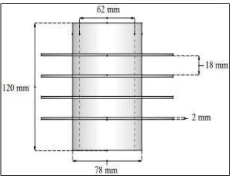
Model Selection
Fig. 1: I C Engine Cylinder Model
Aluminium is selected as a fin material for further analysis by ANSYS. Aluminium is a very light metal with a specific weight. The use of Al in vehicle reduces dead weight and energy consumption while increasing load capacity. Al is a good reflector of visible light as well as heat.
Table – 1
Boundary condition for cylinder
Wind velocity 40 km/hr
Air Temperature Ambient Temperature 27 oC
Atmospheric Pressure 101.325 kPa
Flow Direction Left to Right
III. ANALYSIS OF DIFFERENT FINS ON ANSYS
Case 1: Circular Fin:
Fig. 2: Model of Circular Fin
Type of Element: - Tetrahedral (10 Node) Number of Nodes: - 553071
Number of Element: - 340908 Type of Analysis: - Steady State Domain Type: - Fluid
Domain Material: - cast iron Fin material : alluminium Domain Motion: - Stationary
Heat Transfer Model: - Thermal Energy Turbulence Model: - K-Ɛ
Static Temperature: 25 oC Wind speed : 40 km/hr
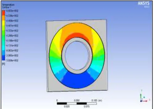
Fig. 3: Temperature Distribution in Circular Fin
Maximum Temperature: 187.3 oC Minimum Temperature: 119.8 oC
Case 2: Rectangular Fin:
Type of Element: - Tetrahedral (10 Node) Number of Nodes: - 553071
Domain Material: - cast iron Fin material : alluminium Domain Motion: - Stationary
Heat Transfer Model: - Thermal Energy Turbulence Model: - K-Ɛ
Static Temperature: 25 C Wind speed: 40 km/hr
Fig. 4: Temperature Distribution in Rectangular Fin
Maximum Temperature: 182.5 oC Minimum Temperature: 148.9 oC
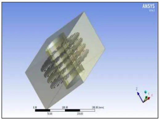
Case 3: Serrated Strip Fin:
Fig. 5: Model of Serrated Fin
Type of Element: - Tetrahedral (10 Node) Number of Nodes: - 553071
Number of Element: - 340908 Type of Analysis: - Steady State Domain Type: - Fluid
Domain Material: - cast iron Fin material: alluminium Domain Motion: - Stationary
Heat Transfer Model: - Thermal Energy Turbulence Model: - K-Ɛ
Fig. 6: Temperature Distribution in Serrated Fin
Maximum Temperature: 189.5 oC Minimum Temperature: 115.5 oC
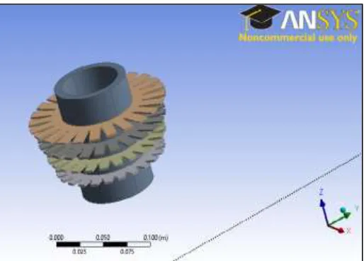
Case 4: Serrated Strip with Taper Fin:
Fig. 7: Model of Serrated Strip with Taper Fin
Type of Analysis: - 3D
Type of Element: - Tetrahedral (10 Node) Number of Nodes: - 553071
Number of Element: - 340908 Type of Analysis: - Steady State Domain Material: - cast iron Fin material : alluminium Domain Motion: - Stationary
Heat Transfer Model: - Thermal Energy Turbulence Model: - K-Ɛ
Fig. 8: Temperature Distribution in Serrated Strip with Taper Fin
Maximum Temperature: 189.5 oC Minimum Temperature: 117.0 oC
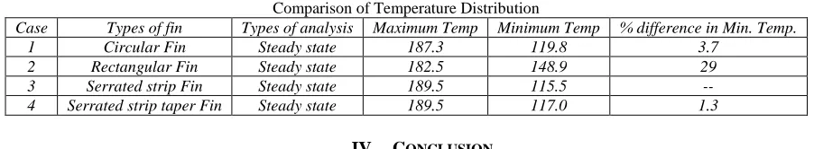
Table – 2
Comparison of Temperature Distribution
Case Types of fin Types of analysis Maximum Temp Minimum Temp % difference in Min. Temp.
1 Circular Fin Steady state 187.3 119.8 3.7
2 Rectangular Fin Steady state 182.5 148.9 29
3 Serrated strip Fin Steady state 189.5 115.5 --
4 Serrated strip taper Fin Steady state 189.5 117.0 1.3
IV. CONCLUSION
For a given condition, the fin material and fin geometry could be optimized in a better way by numerical simulation methods. To increase the cylinder cooling rate the cylinder should have a greater number of fins. Based on review study cylinder heat transfer rate also increase by changing the various types of geometry of fins mounted on it. That can be simulated and validate results by conducting experimental work.
From the present analysis we can say that the serrated strip fin geometry provide effective solution. In this simulation we found that, minimum temperature distribution of serrated strip fin is 29 % less than the rectangular fin and 3.7 % less than the circular fin. By comparing simulation result for surface heat transfer, it is clearly observed that heat transfer enhancement can be performed using same cylinder with different fin profile
REFERENCES
[1] Sanjay Kumar Sharma and Vikas Sharma: “Maximizing The Heat Transfer Through Fins Using CFD As A Tool.” International Journal of Recent advances in Mechanical Engineering (IJMECH) Vol.2, No.3, August 2013.
[2] KM Sajesh, Neelesh Soni and Siddhartha Kosti : “Design Modification and heat flux analysis of air cooled fin” ISSN: 0976-3031, Volume: 7(3) March-2016. [3] Prof. Arvind S. Sorathiya, Manankumar B. Joshi,Prof. (Dr.) Pravin P. Rathod : “Heat Transfer Augmentation of Air Cooled 4 stroke SI Engine through Fins.”
IJREAT International Journal of Recent advances in Engineering & Advanced Technology, Volume 2, Issue 1, Feb-Mar, 2014.
[4] Mohsin A. Ali and Prof. (Dr.) S.M Kherde: “Design Modification and Analysis of Two Wheeler Engine Cooling Fins by CFD.” International Journal of Science, Engineering and Technology Research (IJSETR), Volume 4, Issue 2, February 2015.
[5] Abhishek Mote, Akshay Choukse, Atharva Godbole, Dr. Pradeep Patil, Avinash Kumar Namdeo: “Analysis of Heat transfer through fins of an IC Engine using CFD.” International Research Journal of Engineering and Technology (IRJET), Volume: 03, Issue: 04, Apr-2016.
[6] Prof. Arvind S. Sorathiya, Hiren P. Hirpara, Prof. Dr. P.P. Rathod: “An Effect of Different Parameters of Fins on Heat Transfer of IC Engine.” IOSR Journal of Mechanical and Civil Engineering (IOSR-JMCE), Volume 11, Issue 3 Ver. I (May-Jun. 2014).
[7] JianWen, HuizhuYang, XinTong, KeLi, SiminWang, YanzhongLi : “Configuration parameters design and optimization for plate-fin heat exchangers with serrated fin by multi-objective genetic algorithm.” Energy Conversion and Management 117 (2016) 482-489.
[8] HongbinYan, ShangshengFeng, TianjianLu, GongnanXie: “Experimental and numerical study of turbulent flow and enhanced heat transfer by cross-drilled holes in a pin-finned brake disc.” International Journal of Thermal Sciences 118 (2017) 355-366.