Control of an EV Electrical Differential based on
Neural Network Based
Nader Sargolzaee, Maahdi Ghaseminezhad
*Department of Electrical Engineering, Neyshabur Science and Research Branch, Islamic Azad University, Khorasan Razavi, Iran
Corresponding author email: [email protected]
Abstract: In-wheel-motor drive structure in electric vehicles is a new configuration, in which each of the rear wheels are driven individually by separate electric motors. To guarantee the EV stability with no differential gears, a traction control system is designed. By using separate in-wheel electric motors, EV will be guaranteed to have a perfect controlled torque and speed which will improve the EV safety and stability. In the proposed approach, the vehicle speed is utilized to traction control of the system. This category is different from the wheel speed which is described as an input slip. In this study, we employed a neural network for estimating the vehicle speed. The Simulation results are applied on two 37-kW induction motors and show that the new proposed control strategy increased safety in the system.
INTRODUCTION
Generally, by increasing the population on earth and improving the life-standards, the number of vehicles getting increased (Schafer and Victor, 2000). By increasing in the number of these vehicles, because of the developments on the constructing more and more better vehicles, the need of energy consumption is increased.
Fossil fuels as the most commonly used fuels in the world formed in the geological past from the remains of living organisms in the millions years. Unfortunately, when the fossil fuels get burnt, they release carbon dioxide. This carbon dioxide adds to the greenhouse effect and helps to increase the global warming. Furthermore, they increase the environmental pollution.
From the explained results, we can conclude that the usage of sustainable energy resources becomes a necessary factor for automotive industry. One of the suggested solution in the human lives is to develop the electric vehicles (EV). Unlike conventional vehicles, these vehicles use electric motors for propulsion (Faiz et al., 1996).
There are exist a great deals of attempts to decrease the Electric Vehicle (EV) body mass, like structure and form optimization or by using the special materials (Larminie and Lowry, 2003).
These developments direct the researchers to use the modern configurations by motorized wheels, i.e. motors which are fitted into the wheels of EVs (Faiz et al., 1996). Ordinary structure of EVs by a differential gear, have only one traction-motor driving two wheels. However, the mass of the batteries makes the total mass of the EV to get increased. Because of this problem, an electronic differential (ED) is used instead of the conventional heavy gearbox. This is the most common solution for speed reference evaluation in the double-driven EV. By this technique, in addition to reduce the overall mass, the performance of the EV is also efficiently improved due to the fast response time of the electric motors. Electronic differential can control the speed of each wheels due to satisfy the motion requirements when the EV confront different conditions, like a lane change or curvilinear trajectory (N. Mutoh et al., 2007; N.Mutoh et al., 2006; Rahman et al., 2006).
This approach will also make a reduction in the drive line weight because of the mechanical differential and gear reduction eliminating (A. Haddoun et al., 2006; S. Gair et al., 2004) . This technique has also a big problem and it is how to guarantee the vehicle stability. When the EV is driving in the normal conditions, all drive wheel systems need a symmetrical distribution of torque for both sides.
The adherence coefficient of tires in this condition is changing because of the wheels have different speeds. Hence, we need a traction control to compensate this problem (N. Mutoh et al. 2007).
In this paper, we propose a neural network traction control technique for the electrical differential system of an EV propelled within two separate induction motor drives. Generally, neural networks are become one of the popular research areas in motor drives. Neural networks have abilities to perform on the systems adaptively. Since, using neural networks for control dynamics and system identification have been enhanced increasingly.
Here, we utilized a recurrent neural network (RNN) with two hidden layers to estimate the induction motor speed. Because of the recurrent and multilayer structure, RNNs are robust under parameter variations and system noises.
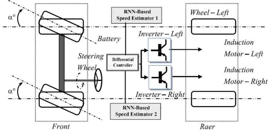
In this paper, we used a vehicle two-rear-wheel drive urban electric vehicle (Fig. 1). Two separate induction motors are coupled and considered for each of the rear wheels (Cordeiro et al., 2006). The energy source of the electric motors comes from the Lithium ions batteries placed under the seats.
Figure 1. EV propulsion system and the system control schematic. Induction Motor
Induction motors are widely used in industrial applications. Indeed, due to their conception and their quite a low cost compared to the cost of other machines makes them as popular motors in the industry. dynamic modeling of the induction motors drive is considered as rotating reference-frame theory and a linear technique. The electrical dynamics of induction motors in the synchronously rotating reference frame (d−q axis) can be described as below:
(1)
qr dr qs ds sl sl r e r e qr dr qs dsV
V
k
k
k
k
k
k
k
k
k
k
k
i
i
dt
d
6 5 4 5 4 2 3 1 3 2 10
0
(2))
(
1
L m r rT
T
J
J
B
dt
d
(3))
(
dr qs qr dst
m
k
i
i
T
where,
dr(
qr)
is the d-axis (q-axis) rotor flux linkages andi
qs(
i
ds)
is the q-axis (d-axis) stator currents and we have:(4)
Electronic Differential (ED)
EDs are a form of differential, which provide the required torque for each driving wheel and allow different wheel speeds. They are used instead of the mechanical differential in multi-drive systems. To describe a smaller turning radius for inner wheels, the inner and outer wheels rotate at different speeds when cornering. The electronic differential employs the motor speed signals and the steering wheel command signal for controlling the power to each wheel to supply the wheels with the required torque. The electrical vehicle’s model can be summarized as below:
where,
describes the steering angle, R is Stator (rotor) resistance and L defines the inductance; since, The linear speed for each drive-wheel’s can be achieved as below (Gasbaoui et al., 2011):(6)
1 2
(R
2)
(R
2)
V V
V
d
V
d
And the angular speeds are:
(7)
1
2
(
2) tan
(
2) tan
est V
est V
L
d
L
L
d
L
here, L illustrates the length of the car and
V is the center of turn angular speed which can be achieved by: (8)1 2
dtan
est est V
L
Note that when this angle is zero the vehicle is travelling on a stright path, and d is the width of the car.
Figure 2. Electronic differential of the EV Neural Network Traction Control
Recently, neural networks have been employed to solve problems in almost all aspects of science and technology. Generally, neural network control strategy includes two steps: system identification and Control. Feedforward network with nonlinear, continuous and differentiable activation functions have universal approximation capability (Stengel, 1991).
Recurrent networks like Elman neural networks (ENNs) can also been utilized for identifying the system. By giving a set of input-output data pairs, the purpose of the system identification is to form a mapping among these data pairs. Such a network is supposed to capture the dynamics of a system.
We can describe the dynamic behavior of an induction motor by current and voltage models (with decoupling control
qr
0
and
dr
cte
.
as below:(9)
(10)
1
0
(k 1)
(k 1)
(k)
(k 1)
(k 1)
(k)
1
0
s m s
r s
s s s
r r
dr dr ds
s s s
qr s qr m s qs
r s
r r
T
L T
T
T
T
i
i
T
L T
T
T
T
We utilized 6 weights for the recurrent network, but only two weightscontain the speed term; since, the other weights can be hold constant and these two weights get trainable for speed estimation. Although, if we consider all the weights as trainable, the speed as well as the rotor time constant can be tuned.
Simulation Results
The trained described recurrent neural network which is utilized in the system control was performed on an EV propelled by two 37-kW induction motor drives. The main purpose of the simulations is to illustrate the efficiency and dynamic performance of the proposed recurrent neural network control technique.
The induction motor and the EV parameters are summarized in the table.1.
Table 1. system parameters Induction Motors Parameters
37 kW, 50 Hz, 400/230 V, 64/111 A, 24.17 Nm, 2960 rpm, Rs = 85.1 mQ, Rr = 65.8 mQ, Ls= 31.4 mH, Lr= 29.1 mH, Lm = 29.1 mH J= 0.23 kg.m2
Electric vehicle Parameters
m = 1540 kg (two 70 kg passengers), A = 1.8 mr, r = 0.3, rr1=0.0055, rr2=0.056, Cad= 0.19, G= 104, hg = 0.95, T =57.2 Nm (stall torque), v0 = 4.155 m/sec, g= 9.81 m/sec2, p = 0.23 kg/m3
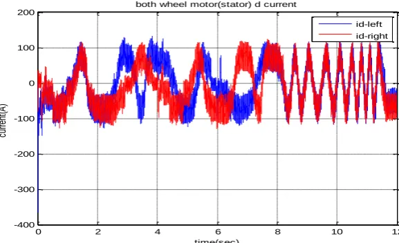
Fig.3 and fig.4 show the current-time graph for the left and right motors in q axis and d axis respectively:
Figure 3. the current-time graph for the left and right motors in q-axis
Figure 4. the current-time graph for the left and right motors in d-axis
0 2 4 6 8 10 12
-200 0 200 400 600 800 1000 1200 1400
time(sec)
cu
rre
nt
(A
)
both wheel motor(stator) q current
iq-left iq-right
0 2 4 6 8 10 12
-400 -300 -200 -100 0 100 200
time(sec)
cu
rre
nt
(A
)
both wheel motor(stator) d current
Figure 9 shows the reference car speed for testing the system.
Figure 5. car reference speed
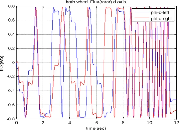
Figs. 6- show the EV dynamics, respectively, the stator and rotor flux (λdr, λdr) and the electromagnetism torque in each induction motor on the left and right wheel drives, with changes in the acceleration pedal position.
Figure 6. Stator flux of the q-axis for both the right and the left wheels.
Figure 7. Stator flux of the d-axis for both the right and the left wheels.
0 2 4 6 8 10 12
0 20 40 60 80 100 120
time(sec)
S
pe
ed
(ra
d/
s)
Car refrence Speed
0 2 4 6 8 10 12
-1 -0.8 -0.6 -0.4 -0.2 0 0.2 0.4 0.6 0.8 1
time(sec)
flu
x(
W
b)
both wheel Flux(stator) q axis
phi-q-left phi-q-right
0 2 4 6 8 10 12
-1 -0.8 -0.6 -0.4 -0.2 0 0.2 0.4 0.6 0.8 1
time(sec)
flu
x(
W
b)
both wheel Flux(stator) d axis
Figure 8. Rotor flux of the d-axis for both the right and the left wheels.
Figure 9. Rotor flux of the q-axis for both the right and the left wheels.
Figure 10. Electromagnetic torque both the right and the left wheels.
0 2 4 6 8 10 12
-0.8 -0.6 -0.4 -0.2 0 0.2 0.4 0.6 0.8
time(sec)
flu
x(
W
b)
both wheel Flux(rotor) d axis
phi-d-left
phi-d-right
0 2 4 6 8 10 12
-0.8 -0.6 -0.4 -0.2 0 0.2 0.4 0.6 0.8
time(sec)
flu
x(
W
b)
both wheel Flux(rotor) q axis
phi-q-left phi-q-right
0 2 4 6 8 10 12
-300 -200 -100 0 100 200 300
time(sec)
el
ec
tr
om
ag
ne
tic
t
or
qu
e(
N
m
)
both wheel electromagnetic torque
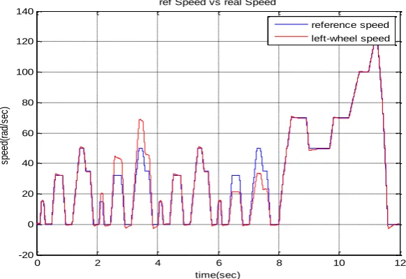
The estimating performances for the recurrent neural network are shown in Fig. 11, which illustrates the reference speed and the estimated value. From the figure, we can clearly conclude that the estimated speed during this test correctly follows the measured one even at zero-speed.
Figure 11. Reference and estimated speed for the left wheel
Figure 12. Reference and estimated speed for the right wheel
Figure 13. Estimated speed for both the right and the left wheel
0 2 4 6 8 10 12
-20 0 20 40 60 80 100 120 140
time(sec)
sp
ee
d(
ra
d/
se
c)
ref Speed vs real Speed
reference speed left-wheel speed
0 2 4 6 8 10 12
-20 0 20 40 60 80 100 120 140
time(sec)
sp
ee
d(
ra
d/
se
c)
ref Speed vs real Speed
reference speed right-wheel speed
0 2 4 6 8 10 12
-20 0 20 40 60 80 100 120 140
time(sec)
sp
ee
d(
ra
d/
se
c)
left wheel speed vs right wheel speed
CONCLUSION
In this, a new technique based on neural network traction control algorithm is presented to control the electrical vehicle with separate wheels. Because the proposed method doesn’t use the mechanical speed transducer, it develops the reliability and decreases the cost of the system drive. as traction control systems considers a precise knowledge about the vehicle dynamics, the dynamic model for the system is utilized. Using the proposed RNN speed estimator will cause to reduce the vehicle cost because of the eliminating the speed transducer which is an expensive device.
REFERENCES
A. Cordeiro, D. Foito, M. Guerreiro: A Sensorless Speed Control System for an Electric Vehicle without Mechanical Differential Gear, IEEE Mediterranean Electrotechnical Conference, Torremolinos, Malaga, Spain, 16 – 19 May 2006, pp. 1174 – 1177.
A. Faiz, C.S. Weaver, and M.P. Walsh. Air Pollutation from Motor Vehicles: Stan- dards and Technologies for Controlling Emissions. Other World Bank Bks. The World bank, 1996. ISBN 9780821334447. URL http://books.google.se/books? id=Hqsyv_KD0lgC.
A. Haddoun et al., “Sliding mode control of EV electric differential system,” in Proc. ICEM, Chania, Greece, Sep. 2006.
Andreas Schafer and David G. Victor. The future mobility of the world population. Transportation Research Part A: Policy and Practice, 34(3):171{205, April 2000.
B. Gasbaoui, A. Chaker, A. Laoufi, B. Allaoua, A. Nasri: The Efficiency of Direct Torque Control for Electric Vehicle Behavior Improvement, Serbian Journal of Electrical Engineering, Vol. 8, No. 2, May 2011, pp. 127 – 146.
J. Larminie, J. Lowry: Electric Vehicle Technology Explained, John Wiley & Sons,England, 2003.
K. M. Rahman et al., “Application of direct-drive wheel motor for fuel cell electric and hybrid electric vehicle propulsion system,” IEEE Trans. Ind. Appl., vol. 42, no. 5, pp. 1185–1192, Sep./Oct. 2006.
M. Wlas et al., “Artificial-neural-network-based sensorless nonlinear control of induction motors,” IEEE Trans. Energy Convers., vol. 20, no. 3, pp. 520–528, Sep. 2005.
N. Mutoh et al., “Electric braking control methods for electric vehicles with independently driven front and rear wheels,” IEEE Trans. Ind. Electron., vol. 54, no. 2, pp. 1168–1176, Apr. 2007.
N. Mutoh et al., “Electric braking control methods for electric vehicles with independently driven front and rear wheels,” IEEE Trans. Ind. Electron., vol. 54, no. 2, pp. 1168–1176, Apr. 2007.
N.Mutoh et al., “Driving characteristics of an electric vehicle system with independently driven front and rear wheels,” IEEE Trans. Ind. Electron.,vol. 53, no. 3, pp. 803–813, Jun. 2006.
S. Gair et al., “Electronic differential with sliding mode controller for a direct wheel drive electric vehicle,” in Proc. IEEE ICM, Istanbul, Turkey, Jun. 2004, pp. 98–103.