A Review of Micro-strip Patch antenna for
UWB Frequency Range
Piush Kumar Sharma
#1, Mrinali Sharma
#2, Pramod Singh
*3#1, #2Student of M.Tech., *3Assistant Professor,
Department of Electronics and Communication, MIET, Meerut, Uttar Pradesh, India
Abstract- According to the antenna theory, the main advantage of micro strip patch antennas (MPA) are low profile, applicable to planar and non planar surfaces, uncomplicated and cheap to fabricate using current printed circuit technology. Therefore in this modern era micro strip patch antenna widely use in communication accessories. In this paper survey of some previous years shows that the various antenna design methods for ultra wideband range like edge tapering slot cutting U-shape, DGS based micro strip patch antennas, patch antenna with partial ground plane, parasitic patch antenna, fractal antenna and reconfigurable antennas. According to the presented study of these antennas for UWB range regulated on single band, double band and multi band frequencies.
Keywords: Ultra Wide Band, DGS, CPW feed, Micro strip patch antenna (MPA), edge tapering, parasitic patch, fractal antenna.
I. INTRODUCTION
Since 1970s the micro-strip antenna in use, primarily it is used for in space technologies [1]. But over the last few years the micro-strip patch antenna is a topic of intense investigation because this technology has many advantages and better future aspects [3]. Some popular advantages of these types of antennas are light weight, smaller size and its lesser volume. These antennas can be easily molded to any desired structure and easily linked to any host surface because of their conformal structures of low profile planar configuration. Similarly we can say that their construction processes are very simple, production of these antennas also so simple and easy, and the major advantage of MPA is low cost. The fabrication process of micro-strip patch antenna is suitable with MMIC (microwave monolithic integrated circuit) and OEIC (optoelectronic integrated circuit) technologies. These types of antennas are efficient with single, dual, triple and multi frequency operations. By using
micro-strip antenna it is accessible to form large arrays with half wavelength or miner spacing [2].
Over all these advantages of micro-strip patch antenna, some limitations are also mentioned like their efficiency and power is low, polarization purity is poor, scan performance is also poor, fake feed radiation and very narrow frequency bandwidth is also the limitation of micro-strip patch antenna [1].
Ultra-wide band is a developing technology because it has some exclusively interesting characteristics which directly connect the scientist and researchers with many fields of wireless communication such as radar technology, medical engineering and other military uses. But in February 2002 the Federal Communications Commission (FCC) is announcing the unlicensed use of ultra wideband in the frequency range from 3.1 to 10.6 GHz for commercial uses which makes it easily achievable for every people and it is beneficial by their useful applications like Wi-Fi, WiMax, Bluetooth etc. UWB is a short range, low energy level radio frequency which able to transfer data from host device to other up to 10m or 30 feet [5]. In this paper the author reviewed some antenna designs which working in UWB range.
II. LITRATURE SURVEY
In [6] proposed a micro strip reception apparatus has a curved shape slot with U-shape opening expelling from this patch. In this design of micro-strip antenna partial ground is used. The proposed antenna in this paper is straightforward and minimal in measure giving broadband impedance coordinating. The whole antenna measure is 44×44×1.6 as appeared in fig. (1). By cutting a space in the patch of U-shape gives the coveted focus indent recurrence of 5.5 GHz as appeared in fig.(2)
International Journal of Engineering Trends and Technology (IJETT) – Volume 50 Number 2 August 2017
opening, at the half guided wavelength interim the attractive field lines make bend and come back to the space locale.
Along these lines to produce a reverberation at a coveted recurrence, the genuine length of the space ought to be moderately equivalent to the half of the guided wavelength for the given score recurrence. Thus in this paper a UWB antenna is available with band dismissal at WLAN frequencies. The proposed antenna manufactured on the electromagnetic programming IE3D utilizing FR4 epoxy substrate with the thickness of 1.6mm.
Fig (1) visualization of antenna [6]
Fig (2) VSWR plot [6]
In the design paper [8] an absconded ground structure is introduced for the recurrence extend 1.5 GHz to 10.5 GHz. In this outline the entire UWB go is secured aside from ISM band. By cutting a U-shape
space on the ground plane accomplishes the indent groups on return misfortune and VSWR plots for maintaining a strategic distance from electromagnetic obstruction (EMI).
Fig (3) Top perspective of proposed antenna [8]
.
Fig (6) iteration steps from i = 0 to i = 4 [9]
Fig (5) Return Loss plot of proposed antenna [8]
The proposed design in this paper exist brief sized micro-strip line fed patch antenna having width Wg=16mm and length of this antenna is Lg=12.45mm. This structure demonstrate the huge data transfer capacity improvement. Proposed antenna reproductions are finished utilizing Anasoft HFSS and the outcomes are confirmed through estimations. Because of the utilization of DGS and UWB extend is separated in four recurrence groups with four reverberation frequencies: 1.8 GHz, 4.19 GHz, 6.7 GHz, and 9.5 GHz. These groups have tasteful transfer speeds and impedance with different applications is likewise maintained a strategic distance.
Now review a new antenna shape on fractal geometry using co-planar waveguide feed for UWB frequency ranges [9]. In this design of antenna used a slotted circular shape for patch, it is iterated utilizing fractal geometry that shows a more extensive transmission capacity and lessened return misfortune. Data transmission of proposed antenna is extended utilizing ground plate alteration and external round span tuning systems. The information impedance of this antenna is 50Ω and seeing as omni-directional example
The circular shape in this antenna having the span of 9.5mm is delineated by the square of 13mm*13mm. the carved square pivoted by the 45° degree and subtracted from the circle and square assessed by the accompanying recipe.
R(i), A(i); for i= 1,2,3,4,…n
A(i)=√2*R(𝑖)2 …………(eqn.1)
R(i)=A(i)/2 ………...(eqn.2)
Here R= span of the circle A= side length of the square
I = number of iterations
Side length of the turned square is found from the eqn. (1) i.e. A=13mm. handle proceed till the fourth cycle. The outlining of every one of the four cycles is appeared in the fig(5). General size of the proposed radio wire is 32mm×32mm×1.6mm with utilizing the dielectric material FR4 with relative permittivity Ɛ=4.4.
Fig (8) Return loss plot for iterations [9]
Above both figures shows the VSWR and Return loss plot simultaneously of the proposed fractal antenna for 5 iterations.
International Journal of Engineering Trends and Technology (IJETT) – Volume 50 Number 2 August 2017
structure for ultra wide band utilization. In this reconfigurable design the bandwidth of composed antenna is increased by defected ground structure. Interesting part of this design is the resonant frequency which can be reconfigured into four different fashions. This reduced antenna can cover the recurrence band or 3 to 22 GHz, it can be likewise play out the operation of expulsion recurrence band or stop band in various styles. Occupy the method of antenna is finished by the three stick diode switches that are set in ground plane. In the accompanying fig.(9) demonstrates the
geometry of proposed antenna.
Fig (9) Antenna structure [10]
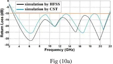
This antenna is simulated and analyzed by using the Anasoft HFSS Software and also find S parameters with the same. To verify the results of the same antenna parameters the CST microwave Studio Software is used.
Return loss of this antenna shown in the following fig.(10a), (10b) and (10c) with different modes
Fig (10a)
Fig.(10a) shows the simulation result of return loss and frequency pattern measured by both HFSS and
CST software when the all switches of antenna are off [10] .
Fig (10b)
Fig (10b) shows the return loss of antenna when both the switches (switch 1 and switch 2) are off and the remaining switch 3 is on [10].
Fig (10c)
The return loss plot in fig.(10c) when only switch 2 is off and remaining switch 1and 3 are on [10].
Fig.(10d)
The return loss plot in fig.(10d) when only switch one is off and switch 2 and 3 are on [10].
Another study of partial ground structure with slot cut in patch is presented in [11]. This design is also provides a filtering property to avoid the coexisting issue between ultra wide band system and other narrowband systems. The band stop function of this antenna is successfully remove frequency band of wireless area network (WLAN). An altered H shape slot is inserting in the patch of antenna to provide the stop band from 5.15GHz to 5.85GHz. Fig.(11) shows the geometry of this antenna.
Fig (11) Front view of antenna [11]
Dimensions of above geometry of antenna is define as L=21mm, W=23.5mm, Lh =8.6mm, Wh=4.7 and t=0.5mm.
Fig.(12) shows the return loss of this antenna, according to this return loss plot the minimum return loss is about -28dB at the frequency 4.5GHz and the entire frequency range of this antenna is start from 2.6GHz to 10.8GHz with the stop band from 5.15GHz to 5.85GHz. Antenna covers the ultra wideband range successfully and it is useful for the numerous UWB applications. It is able to reduce the coexisting issue between UWB and WLAN services.
Fig (12) Return Loss plot [11]
Now discuss another UWB antenna technology, it is presented in [13] it is a microstrip patch antenna technology using defected ground structure and parasitic spilt ring. In this paper author presented a new method of broadening the impedance axial ratio bandwidth of circularly polarized microstrip antennas. The design aspect of this antenna is presented in the fig.(12).
III. TABLE 1
The dimensions of the antenna
Dimension g w c f S
mm 35 16.7 3.3 4.2 1.2
Dimension L1 L2 L3 L4 L5
mm 4 4 5.4 13.5 0.5
Dimension h m D Z1 Z2
mm 3.18 12.2 4.2 1.2 1.5
International Journal of Engineering Trends and Technology (IJETT) – Volume 50 Number 2 August 2017
Fig.(12a) front view of antenna [13]
Fig (12b) bottom view of antenna
Fig.(12a) and fig.(12b) shows the front and back views of this antenna.
and defected ground structure is used for to minimize the size of the antenna. The major achievement of this antenna is the -10dB impedance bandwidth is improved from 4.12% to 6.26% in simulation and from 4.02% to 5.69% in measurement. The 3dB axial-ratio bandwidth are achieved in simulation is improved from 1.02% to 1.53%.
The method is described in this paper is simple in design and better in performance.
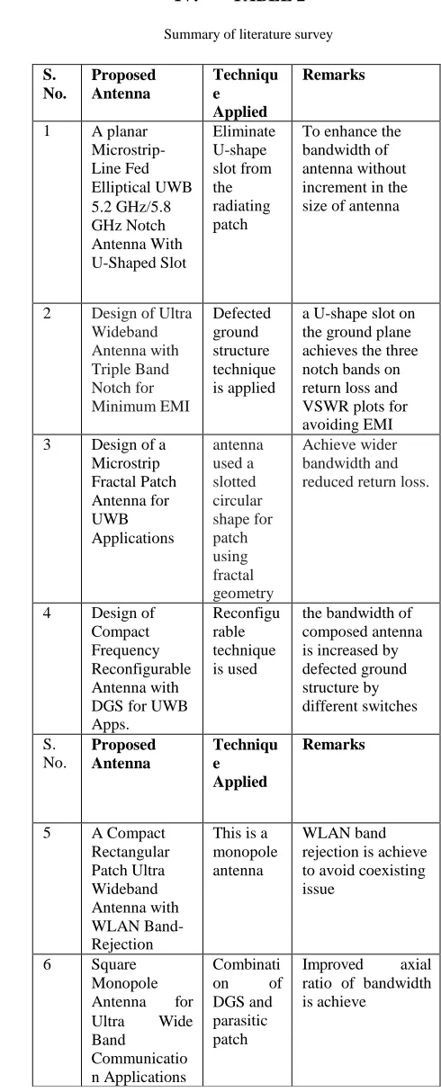
IV. TABLE 2
Summary of literature survey
S. No. Proposed Antenna Techniqu e Applied Remarks
1 A planar
Microstrip- Line Fed Elliptical UWB 5.2 GHz/5.8 GHz Notch Antenna With U-Shaped Slot Eliminate U-shape slot from the radiating patch
To enhance the bandwidth of antenna without increment in the size of antenna
2 Design of Ultra
Wideband Antenna with Triple Band Notch for Minimum EMI Defected ground structure technique is applied
a U-shape slot on the ground plane achieves the three notch bands on return loss and VSWR plots for avoiding EMI
3 Design of a
Microstrip Fractal Patch Antenna for UWB Applications antenna used a slotted circular shape for patch using fractal geometry Achieve wider bandwidth and reduced return loss.
4 Design of
Compact Frequency Reconfigurable Antenna with DGS for UWB Apps.
Reconfigu rable technique is used
the bandwidth of composed antenna is increased by defected ground structure by different switches S. No. Proposed Antenna Techniqu e Applied Remarks
5 A Compact
Rectangular Patch Ultra Wideband Antenna with WLAN Band- Rejection
This is a monopole antenna
WLAN band rejection is achieve to avoid coexisting issue
6 Square
Monopole
Antenna for
Ultra Wide
Band
Communicatio n Applications
Combinati
on of
DGS and parasitic patch
Improved axial
V.
CONLUSION
This paper shows the review and literature survey of techniques and design of the microstrip patch antenna for ultra wide band frequency range. By adopting one of any technique of designing antenna some of disadvantages or limitations of conventional microstrip characteristics is improved. All discussed antennas is work for UWB and after this work author feels that further research and more work is needed in these areas. Design of microstrip patch antenna has been reviewed in this paper based on HFSS, CST Microwave and IE3D software.
References
[1] Constantine A. Balanis “Antenna Theory: Analysis And Design” 3rd edition, John Wiley and sons, 2005.
[2] John D Kraus, Ronald J Marhefka, Ahmad S khan “Antenna and Wave Propagation” 4th edition, Tata
McGraw Hill, special Indian edition 2010.
[3] Hanae Elftouh, Naima A. Touhami, Mohamed Aghoutane, Safae El Amrani, Antonio Tazon and Mohamed Boussouis “Miniaturized Microstrip Patch Antenna with Defected Ground Structure” Progress In Electromagnetics Research C, Vol. 55, 25–33, 2014. [4] Jianli Pan “Medical Applications of Ultra-WideBand
(UWB)” 2008
[5] Yusnita Rahayu, Tharek Abd. Rahman, Razali Ngah, P.S. Hall “Ultra Wideband Technology and Its Applications” IEEE, 2008.
[6] Jyoti R. Panda and Rakesh S. Kshetrimayum “A planar Microstrip-Line Fed Elliptical UWB 5.2 GHz/5.8 GHz Notch Antenna With U-Shaped Slot”, Int’l conf. on computer & communication Technology, IEEE, 2010. [7] S.B. Cohn, “Slot line on a dielectric substrate,” IEEE
Trans. Microw. Theory Techn., vol. MTT-17, no. 10,pp. 768–778, Oct, 1969.
[8] Pramod Singh and Rekha Aggarwal, “Design of Ultra
Wideband Antenna with Triple Band Notch for Minimum EMI” Microwave and Optical Technology Letters, July 2016.
[9] K. Vinoth Kumar, V. Indu Nair, V. Asokan, “Design of a Microstrip Fractal Patch Antenna for UWB Applications”, IEEE Sponsored 2nd International Conference on Innovations in Information Embedded and Communication Systems, 2015.
[10] Esmail Nasrabadi, Pejman Rezaei, Sedighe Saghayi “Design of Compact Frequency Reconfigurable Antenna with Defected Ground Structure for UWB Applications”, Department of Electrical and Computer Engineering Semnan University Semnan, Iran; IEEE 2014.
[11] Y.E. Jalil, C.K. Chakrabarty, B. Kasi “A Compact Rectangular Patch Ultra Wideband Antenna with WLAN Band-Rejection”, IEEE Student Conference on Research and Development, Putrajaya, Malaysia, 2013. [12] M. Gopikrishna, D. D. Krishna, A. R. Chandran and C.
K. Aanandan, “Square Monopole Antenna for Ultra
Wide Band Communication Applications” J. of Electromagn. Waves and Appl., Vol. 21, No. 11, 1525– 1537, 2007
[13] J.S. Park, J.H. Kim, J.H. Lee, and S.H. Kim, and S.H.
Myung, “A novel equivalent circuit and modeling method for defected ground structure and its application to optimization of a DGS lowpass filter”, IEEE MTT-S Int Dig (2002), Seattle, WA, 417–420.
[14] L. Wen Tao and S. Xiao Wei, and Y. Qiang Hei,
“Novel planar UWB monopole antenna with triple band-notched characteristics”, IEEE Antennas Wireless Propag Lett 8 (2009)
[15] J. R. Kelly, P. S. Hall, and P. Gardner, "Band-Notched UWB Antenna Incorporating a Microstrip Open-Loop Resonator," IEEE Transactions on Antennas and Propagation, vol. 59, pp. 3045 - 3048, 2011.
![Fig (2) VSWR plot [6]](https://thumb-us.123doks.com/thumbv2/123dok_us/8584947.1719707/2.612.340.525.411.634/fig-vswr-plot.webp)
![Fig (6) iteration steps from i = 0 to i = 4 [9]](https://thumb-us.123doks.com/thumbv2/123dok_us/8584947.1719707/3.612.76.296.85.227/fig-iteration-steps-i-i.webp)