Improvement in Flexibility of ECCD by Upgraded ECH Antenna
System on LHD
∗
)
Yasuo YOSHIMURA, Yoshiro NARUSHIMA, Shin KUBO, Takashi SHIMOZUMA,
Hiroe IGAMI, Hiromi TAKAHASHI, Toru I. TSUJIMURA, Ryohei MAKINO, Satoshi ITO,
Kota OKADA, Sakuji KOBAYASHI, Yoshinori MIZUNO, Yuki GOTO
1), Ryuichi SAKAMOTO,
Akira EJIRI
2), Takashi MUTOH, Hiroshi YAMADA, Akio KOMORI, Yasuhiko TAKEIRI
and the LHD Experiment Group
National Institute for Fusion Science, 322-6 Oroshi-cho, Toki 509-5292, Japan
1)Graduate School of Engineering, Nagoya University, Nagoya 464-8601, Japan 2)Graduate School of Frontier Science, University of Tokyo, Kashiwa 277-8561, Japan
(Received 29 November 2015/Accepted 23 February 2016)
The power injection system for electron cyclotron heating (ECH) and electron cyclotron current drive (ECCD) was modified and upgraded. An outside horizontal port 2-O on the Large Helical Device (LHD) was furnished with two antenna systems for the EC-waves of the frequencies of 77 and 154 GHz, respectively. In ad-dition to them, two new antenna systems for 77 and 154 GHz waves were installed in the 2-O port. Each antenna in the 2-O port has wide range of EC-wave beam direction control so that these are suitable for ECCD which requires toroidally oblique EC-wave beam injection. In the LHD 18th experimental campaign in 2014-2015, an ECCD experiment with second harmonic resonance condition, on-axis magnetic field of 1.375 T for 77 GHz waves, was performed in which some combination patterns of two 77 GHz ECCDs were applied. The discharges of dual co- and dual counter-ECCDs showed remarkable plasma currents of∼ ±26 kA in both of the co- and counter-directions, by 6 s pulse duration and injection powers of 366 and 365 kW. The new antenna has nearly the same capability for ECCD with that of the existing antenna. The improvement in the flexibility of the ways of applying plural ECCDs will offer a highly useful tool for investigations on the phenomena concerning with the plasma current such as magnetohydro-dynamics.
c
2016 The Japan Society of Plasma Science and Nuclear Fusion Research Keywords: electron cyclotron current drive, ECCD, LHD DOI: 10.1585/pfr.11.2402036
1. Introduction
Electron cyclotron current drive (ECCD) is an at-tractive tool to control plasmas. Using well-focused EC-wave beams, plasma currents can be driven locally so that ECCD can control the profiles of plasma current and rota-tional transform which affect the magnetohydro-dynamics (MHD) activities [1–3].
Experimental and theoretical investigations on the ECCD have been performed both in the tokamaks [4–7] and stellarators [8–14]. Though the stellarators do not need plasma current for plasma confinement, the capability of current profile control is effective for fine plasma control. The ECCD can work for keeping an optimized profile of rotational transform, or for local modification of the rota-tional transform profile. Eliminating or shifting rarota-tional surfaces would be effective for suppressing instabilities re-lated to an existence of rational surfaces.
In the large helical device (LHD), using 84 or 77 GHz
author’s e-mail: [email protected]
∗)This article is based on the presentation at the 25th International Toki
Conference (ITC25).
EC-waves, second harmonic ECCD experiments have been performed. EC-driven currents in both the co- and counter-directions were confirmed [12–14], and the current di-rection obeyed Fisch-Boozer theory [15]. The maximum driven current was 40 kA, with a 77 GHz EC-wave of 775 kW power injected for 8 s.
In 2014, the EC-wave power injection system on the LHD was upgraded so that two power injection antenna systems were newly installed in an equatorial port, 2-O port, additionally to the existing two antenna systems in the port. The new antenna systems can control the EC-wave beam direction with wide range so that these are available for ECCD as the existing antennas. Combination of these antennas for ECCDs can extend the experimental flexibil-ity extensively.
In this paper, recent results of dual ECCD experiment in the LHD are described. The LHD and the system for ECCD experiment are briefly indicated in Sec. 2. Section 3 describes observations of plasma currents obtained in the dual ECCD experiment. Also, evaluation of current drive efficiency of one of the new antenna systems is
com-c
2016 The Japan Society of Plasma
mented. The prospects of future investigations using the plural ECCDs are discussed in Sec. 4. Then, the contents of this paper are summarized in Sec. 5.
2. Upgraded ECH System on the LHD
The LHD is a helical device with toroidal period num-berm=10 and polarityl=2. The magnetic field structure including rotational transform for plasma confinement is completely generated by external superconducting mag-nets such as a pair of helical coils and three pairs of poloidal coils. The magnetic axis position Rax of LHD plasmas can be adjusted in the range from 3.42 to 4.1 m. In the typical case ofRax=3.6 m, the averaged minor radius is 0.58 m, the plasma volume is 30 m3, and the maximumvalue of the magnetic field at the magnetic axis averaged in the toroidal direction, Bt, is 2.85 T. Those values and
characteristics of the magnetic field configuration such as rotational transform profile and magnetic field along mag-netic axis are dependent onRax. WhenRaxis set at 3.75 m,
the magnetic field along magnetic axis is nearly constant, while withRax=3.6 m or 3.9 m, magnetic ripples of about
5% exist [13].
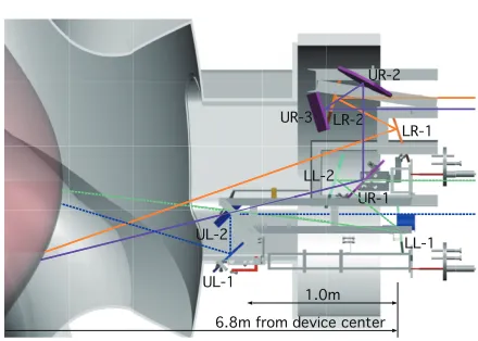
The ECH system in NIFS is furnished with seven working gyrotrons. The oscillation frequencies are 77 (three gyrotrons), 154 (two gyrotrons), 84, and 82.7 GHz. The 77 and 154 GHz gyrotrons have been newly developed by collaboration with the University of Tsukuba and in-stalled on the LHD ECH system in recent years [16–18]. The antenna systems in a top port (5.5-U) and in an equa-torial port (2-O) are used for the 77 and 154 GHz power injections. In the 2-O port, four antenna systems are installed. Evacuated corrugated waveguide transmission lines with the inner diameter of 88.9 mm transmit the pow-ers from the gyrotrons to the antennas. Figure 1 shows a drawing of mirror sets of four antenna systems. The up-per two antennas, 2-OUR and UL, were newly installed in 2014 corresponding to the increase in the number of gy-rotrons, additionally to the previously installed lower two antennas LR and LL. The EC-wave beams are injected from the right side of Fig. 1 and transmitted by the mir-rors counting down the numbers of mirmir-rors labeled in the figure.
Each EC-wave beam injection system in the 2-O port is furnished with a focusing mirror (mirrors labeled as “2” in Fig. 1) and a 2-dimensionally steerable plane mirror (la-beled as “1”). The positions and surface shapes of the focusing mirrors are determined and designed based on the Gaussian optics to make matching of the sizes of two circular Gaussian beams (incident and reflected beams on the focusing mirrors) having waist positions at the waveg-uide opening and the plasma core region, respectively. The steerable plane mirrors enable precise beam direction con-trol. The designed waist radii of the EC-wave beams in-jected from the 2-OLR, UR, LL, and UL antennas are 35, 65, 35, and 34 mm, respectively. The waist radii are
deter-Fig. 1 Schematic drawing of the upgraded ECH power injection antenna systems in the 2-O port (top view). The EC-wave beams come from the right side. The plasma boundary is seen as the pink surface at the left side. Examples of the beam center paths are drawn.
mined as small as possible under the conditions/limitations of the wave frequency, available space for setting mirrors, and structure of transmission line outside the vacuum ves-sel. The waist radii are nearly or smaller than 1/10 of the toroidal average plasma minor radius (∼0.6 m), ensuring enough localized power deposition profiles for physics re-searches.
The 2-OUR antenna system is furnished with an ad-ditional diffusing mirror UR-3 in order to satisfy the beam size matching at the UR-2 mirror surface, with the beam waist radius in the plasma core region as small as possi-ble. Here, assuming a smaller radius in the plasma core re-gion than 65 mm requires larger sizes for the mirrors UR-1 and UR-2 than the sizes available for these mirrors in the given space. To achieve the injection beam waist radius of 65 mm in the plasma core region, the beam released from the waveguide opening should be slightly expanded by us-ing the diffusing mirror UR-3.
The ECCD experiment described in this paper was performed with the magnetic configuration ofRax=3.75 m
to minimize the effect of magnetic ripple on ECCD. The magnetic field on the magnetic axis is 1.375 T, that is, the second harmonic resonance field for the frequency of 77 GHz. At Rax =3.75 m, on-axis fundamental (second
harmonic) resonance condition for 77 (154) GHz wave by settingBt=2.75 T is not available due to a limitation on
the highest current in the helical coils. The 77 GHz EC-waves were applied from the 2-OLR and UR antennas for ECCD, and from the 5.5-U antenna for ECH.
3. Dual ECCD Experiment
of on-axis magnetic field, sine-curve-like systematic varia-tion of the EC-driven current was observed. The maximum driven current with 8 s pulse duration was∼ −40 kA, with the EC-wave power of 775 kW,N//of around−0.3, the line average electron densityne_aveof 0.3×10¹⁹m−3, the
cen-tral electron temperatureTe0of 3 keV,Raxof 3.75 m, andBt
of 1.375 T. The maximum current drive efficiency defined asγ=neRaxIECCD/Pabsat the optimum N//was evaluated
as 5.8×10¹⁷AW−1m−2[14].
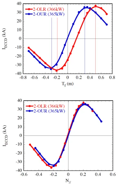
For the dual ECCD experiment, optimum EC-wave beam direction settings for 2-OLR and UR antennas were investigated using a ray tracing code, TRAVIS [19]. Figure 2 plots the calculated driven currents as functions of an experimental beam direction setting parameterTf, and corresponding values ofN//. Tf means the toroidal posi-tion on a virtual target screen set vertically atR=3.9 m. Due to the difference in the start positions (positions of the final plane mirrors) of the two beams, dependences of variation ofIECCDs show a difference when plotted against
Tf, while the dependences and the amounts of the IECCD
are nearly identical when plotted againstN//. Thus it is considered that these two antenna systems have the equal characteristics and performance for ECCD. According to the calculation, the dual ECCD experiment was performed with the beam directions withN//to be∼ ±0.2 as
Fig. 2 Calculated driven currents by TRAVIS code as functions of experimental beam direction setting parameterTfand
corresponding parallel component of refractive indexN//
to the magnetic field direction.
co-ECCD by the UR antenna:Tf=0.3 m (N//=0.195)
co-ECCD by the LR antenna:Tf =0.5 m (N//=0.204)
ctr-ECCD by the UR antenna:Tf =−0.3 m (N//=−0.195)
ctr-ECCD by the LR antenna:Tf =−0.2 m (N//=−0.229).
The calculation was originally performed using as-sumed plasma parameters. After the experiment, the calcu-lation was performed again using the parameters obtained in the experiment, and plotted in Fig. 2. Except for the absolute values of the driven currents, the dependences of the driven currents onTf and N// were not affected. So
far, quantitative agreement can not be mentioned between the calculated and the experimentally obtained currents de-scribed below.
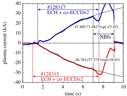
Figure 3 shows the waveforms of EC-wave injection power, line average electron density ne_ave, and plasma stored energyWp in the dual ECCD discharges #128315 (counter) and #128317 (co). The EC-wave injections were started at 1.0 s (#128315) or 1.5 s (#128317), and the gen-erated plasmas were sustained till 7 s with the EC-waves. After 7 s, the plasmas were sustained with neutral beam injections (NBIs). The injected powers for ECCD were nearly equal, 366 kW from the 2-OLR antenna and 365 kW from the 2-OUR antenna. An ECH power of 271 kW was also applied. Thene_avewas kept at∼0.45×10¹⁹ m−3for ∼6 s, and theWpwas∼25 kJ in both discharges.
These two discharges are nearly identical except for the plasma currents plotted in Fig. 4 and the start tim-ings. In the dual counter-ECCD discharge #128315, the plasma current Ip continuously decreases with time and
it reaches−26 kA at 7 s, while in the dual co-ECCD
Fig. 4 Time evolutions of plasma currents in the dual ECCD ex-periment. Blue line: co-ECCD #128317 and red line: counter-ECCD #128315.
charge #128317,Ipcontinuously increases to 27 kA at 7 s.
The time evolution of the plasma currents is not saturated. If exponentially saturating evolution is assumed as seen in Fig. 4, the saturated values ofIpwould be expected to be ∼ ±47 kA, respectively.
To compare with the previous ECCD experiment per-formed with 2-OLR antenna alone described briefly at the beginning of this section and precisely in Ref. 14, an over-all current drive efficiencyγ at the timing∼6 s after the plasma startup is roughly evaluated as
γ=0.45×1019×3.75×26/(366+365) AW−1m−2
=6.0×10¹⁷AW−1m−2.
The previous value 5.8×10¹⁷ AW−1m−2 was
evalu-ated at the timing 8 s after the plasma startup. To compare with the new result here directly considering the time evo-lution of Ip, the previousγ should be corrected to be at
the timing 6 s after the plasma startup, and this yieldsγas 5.0×10¹⁷ AW−1m−2. It is still a similar value with that obtained in the dual ECCD experiment. Thus, it is con-firmed that the new 2-OUR antenna has almost the same capability for ECCD with the existing LR antenna, from the calculated and the experimentally obtained results.
4. Discussions
Combination of plural ECCDs can improve the exper-imental flexibility. With the magnetic axis positions ex-cept for Rax = 3.75 m, magnetic ripple exists in the
on-axis magnetic field in the magnetic field configurations of LHD, and the standard Rax position of LHD
experi-ments is 3.6 m. However, applying dual co-, dual counter-, and cancelling-ECCDs enables experimental setups with co-, counter-, and no-ECCD currents without changing the EC-wave power and its deposition profile, that is, without changing the electron temperature and its profile. The abil-ity of varying plasma current widely and solely will con-tribute to the investigations on the effect of the plasma
cur-rent on the phenomena such as MHD activities, formation of internal transport barriers, appearance and vanishing of magnetic stochasticity, and so on.
Dual co- and counter-ECCDs with higher power will drive plasma currents as large as comparable with the high power NB-driven currents. Restraint of beta valueβ[20] and its local gradient dβ/dρatρ=0.5 [21] due to an on-set of magnetic fluctuations caused bym/n=2/1 unstable mode (m: poloidal andn: toroidal mode numbers here) as a dominant component are observed in LHD, and a stabiliza-tion of them/n=2/1 mode by the elimination ofι/2π=0.5 surface resulting in an improvement of β by more than 30% has been confirmed [20]. Though those discharges in Refs. 20 and 21 were performed with the magnetic field of 0.5 T for high-βexperiment and the elimination of theι/2π
=0.5 surface was achieved by large co-current drive with tangential NBIs, performingι-profile control by ECCD at an appropriate magnetic field would contribute to an im-provement in plasma performance.
5. Conclusions
The upgrade of EC-wave injection mirror antenna tems in the 2-O port of the LHD, where two antenna sys-tems were newly installed in the 2-O port additionally to the existing two antenna systems, enabled plural ECCDs using these antennas. Second harmonic dual ECCD exper-iment using 77 GHz waves was described in this paper.
Comparison with the former ECCD experimental re-sult performed using one of the existing antenna showed that both of the existing and the new antenna systems for 77 GHz EC-wave injection are nearly equal at the perfor-mance for ECCD. Injection power of 731 kW in total gen-erated∼26 kA in both of the co- and counter-directions by 6 s pulse duration, and the higher current can be expected by longer pulse duration.
By using these antennas, experimental flexibility was improved intensely. Setting the antennas as dual co-, dual counter-, and cancelling-ECCDs enables the wide varia-tion of plasma current keeping other plasma parameters such as electron temperature and its profile. This property offers an effective tool for the investigation on the phenom-ena concerning with the plasma currents.
Acknowledgments
The authors would like to express their thanks to NIFS stafffor performing the LHD experiments. This work was supported by JSPS KAKENHI Grant Numbers 21560862 and 24561029.
[1] V. Erckmann and U. Gasparino, Plasma Phys. Control. Fu-sion36, 1869 (1994).
[2] B. Lloyd, Plasma Phys. Control. Fusion40, A119 (1998). [3] R. Prater, Phys. Plasmas11, 2349 (2004).
[6] A.C.C. Sipset al., Nucl. Fusion47, 1485 (2007). [7] A. Isayamaet al., Nucl. Fusion49, 055006 (2009). [8] H. Maassberget al., Plasma Phys. Control. Fusion47, 1137
(2005).
[9] G. Motojimaet al., Nucl. Fusion47, 1045 (2007). [10] K. Nagasakiet al., Nucl. Fusion50, 025003 (2010). [11] K. Nagasakiet al., Nucl. Fusion51, 388704 (2011). [12] Y. Yoshimuraet al., Fusion Sci. Technol.58, 551 (2010). [13] Y. Yoshimura et al., J. Plasma Fusion Res.6, 2402073
(2011).
[14] Y. Yoshimura et al., J. Plasma Fusion Res.7, 2402020
(2012).
[15] N.J. Fisch and A.H. Boozer, Phys. Rev. Lett. 45, 720 (1980).
[16] H. Takahashiet al., Fusion Sci. Technol.57, 19 (2010). [17] T. Shimozumaet al., Fusion Sci. Technol.58, 530 (2010). [18] T. Kariyaet al., Nucl. Fusion55, 093009 (2015).
[19] N.B. Marushchenko et al., Phys. Plasmas 18, 032501 (2011).