WWJMRD 2015; 2(9): 32-37 www.wwjmrd.com Impact Factor MJIF: 4.25 e-ISSN: 2454-6615
Tamer Aboufoul Faculty of Engineering & Information Technology, Al-Azhar University. Gaza, Palestine
Mustafa H. Abu Nasr Faculty of Engineering & Information Technology, Al-Azhar University. Gaza, Palestine
Asmaa Fhead
Faculty of Engineering & Information Technology, Al-Azhar University. Gaza, Palestine
Qamar Alfalojy
Faculty of Engineering & Information Technology, Al-Azhar University. Gaza, Palestine
Esraa Alzeny
Faculty of Engineering & Information Technology, Al-Azhar University. Gaza, Palestine
Samy S. Abu Naser Faculty of Engineering & Information Technology, Al-Azhar University. Gaza, Palestine
Correspondence: Samy S. Abu Naser Faculty of Engineering & Information Technology, Al-Azhar University. Gaza, Palestine
A novel UWB wearable antenna
Tamer Aboufoul, Mustafa H. Abu Nasr, Asmaa Fhead, Qamar Alfalojy,
Esraa Alzeny, Samy S. Abu Naser
Abstract
This paper presents a novel design of a wearable tapered slot Vivaldi antenna. The operating frequency of design is between 300MHz and 8 GHz. Jeans Cotton fabric with pure 100% Cotton has been used as the substrate with dielectric constant 1.56, while the radiating element patch and ground plane are made up of aluminum as conducting material. The analysis of the structures are carried out using CST Microwave Studio. Simulated results in terms of return loss, bandwidth, radiation pattern, current distribution as well as gain and efficiency are presented to validate the usefulness of the proposed design and different bending conditions are presented in this paper.
Keywords: UWB Antenna; Wearable antenna; Antenna Bending; Vivaldi antenna
Introduction
In the recent years, body-centric wireless communication becomes an important part of the fourth generation mobile communication systems (4G). In supporting the increasing interest in antennas and propagation research for body communication systems, the IEEE 802.15 standardization group has been established to standardize applications intended for on-body, off-body or in-body communication [1]. One of the dominant research topics in antennas for body-centric communications is wearable. A wearable antenna is meant to be a part of the clothing used for communication purposes, which includes tracking and navigation, mobile computing and public safety. Wearable antenna requirements for all modern application require light weight, low cost, almost maintenance-free and no installation [1,6-10].
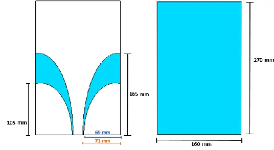
Fig 1: Dimension details of the proposed antenna
In this paper, the proposed design aimsto improve the design of the antenna in [2], that can
be integrated as part of garment and to be worn on the body, with the ability to extend
wireless range that use ultra-wide band in addition to the low frequency The rest of the paper is organized as follows: Section II presents antenna design and operation, whereas Section III discusses simulation results. After that in Section IV bending conditions of wearable antenna are discussed, While Section V illustrates the implementation and testing results for the antenna and finally, Section VI describes the conclusion.
Antenna Design and Operation
The proposed antenna (270mmX160mm) has a permittivity of (1.59) and thickness of 0.75mm for the substrate) and is fed through a 50Ω miniature adapter (SMA) connector.
As stated previously the dimensions of this antenna have been obtained using CST Microwave studio[3]. Fig. 1 shows the proposed antenna geometry. The arc of the two tapered slots is defined by the arc of an ellipse. The length of the semi-major and semi-minor axis of the smaller ellipse are (105) mm and (69) mm respectively and that for the bigger ellipse are (165) mm and (71) mm.
A prototype antenna was fabricated to verify the performance. Fig. 2 shows the proposed prototype antenna. Jeans Cotton fabric has been used as the substrate of the antenna, while the radiating element patch and ground
plane are made from aluminum tape. However, using the
copper tape instead of aluminum gives better results for the antenna.
Fig 2: Fabricated prototype.
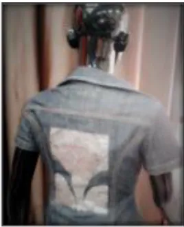
Fig 3: Prototype antenna fabrication on a jeans shirt.
Simulation Results A. Reflection Coefficient
Fig. 4 below represents the return loss of the proposed design.
Fig 4: Simulated reflection coefficient of the proposed antenna design using Aluminum for conducting material
B. Surface current.
Fig. 5(a) and 6(b) show the simulated surface current distributions of the proposed antenna design at different frequencies.
C. Radiation Patterns and Gain.
The antenna pattern describes the relative strength of the radiated field in multiple directions from the antenna. It includes both reception and transmission pattern. 2D radiation patterns (polar) in free space at different
frequencies when using Jeans Cotton textiles for substrate and Aluminum for the conductive material of the proposed antenna are shown in the Figures 6(a) and 6(b). The antenna gain ranges from 1-10 dB as shown in Fig. 7 which can be considered as good results.
(a)
(b)
Fig 6: Far field polar plot (2D) on free space at Frequency of (a) 2.4 GHz, (b) 5.8 GHz.
Fig 8: Simulated total efficiency in free space.
D. Efficiency.
Fig. 8 shows the measured total efficiency when the
antenna is in free space. Total efficiency results usually
give better indication than return loss results to highlight
the filtering performance of the antenna; thisis because the
antenna total efficiency not only accounts for the input
mismatch of the antenna but also accounts for the ohmic
losses in the antenna [4, 5].
Bending of Wearable Antenna
In wearable systems, It is very difficult to keep the antenna flat all the time especially when the antenna is made of textile materials. Moreover, the wearable antenna bends continuously due to the human body movements and to
ensure theantenna performance in real life applications is
up to mark, especially when the antenna is applied to
rounded parts of the body, such as the torso, it becomes
necessary to investigate the antenna’s performance
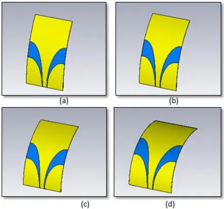
characteristics under different bending conditions. Based on the analysis, the proposed design have been tested under severe conditions to examine its ability to keep its operating bandwidth as desirable, the antenna have been bent with different angles as shown in Fig. 9.
Fig 9: Simulation bending of antenna with four
different angles (a) bend of 30 degree, (b) bend of 45
degree, (c) bend of 60 degree, (d) bend of 90 degree.
Fig. 10 illustrates the measured results of the return loss when different bending situations are applied to the proposed antenna, S11 parameter almost still the same, no
major differences occur.Therefore, the antenna will be able
to operate within the desired frequency range. The bending conditions were differentiated using degrees and when we increase the angle degree, the antenna will be bent more.
Fig 11: Simulated total efficiency of bent antenna.
Implementation
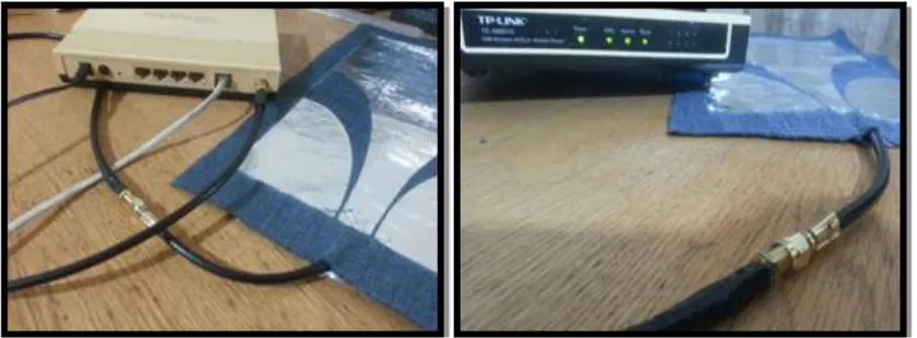
The antenna is tested by using a router for Wi-Fi signals and it has a good result as the connection was valid and it transmitted for approx. 15 meters with different movement and bending positions. To measure the signal strength on the receiver (a mobile in this case), an application which is Wi-Fi analyzer for android phones is used. This application
present the signal strength in different ways such as charts or a specific values of the strength measured in dBm to show the less crowded channels and networks available. Signal strength values obtained in dBm at the same distance, for the router original antenna was [-38dBm] and for the proposed antenna was approx. [-15dBm].
Fig 12: Connection between the antenna prototype andthe router device.
Conclusion
A UWB and UHF planar and wearable antenna design using a Vivaldi antenna has been proposed. The antenna -6dB bandwidth ranges from 200 MHz up to 8 GHz. The antenna has stable radiation patterns, good gain and efficiency. The antenna has been used to receive 2.4 GHz Wi-Fi signals. The antenna can be easily integrated on wearable clothes and can be used for both civil and defense applications.
References
1. Hall, P. S., and Hao, Y., “Antennas and Propagation
for Body Centric Communications”, European Conference on Antennas and Propagation (EuCAP), November 2006.
2. A. Rahman and Y. Hao, "A novel tapered slot
CPW-fed antenna for ultra-wideband applications and its
on/off-body performance," 2007 International
workshop on Antenna Technology: Small and Smart Antennas Metamaterials and Applications, Cambridge, 2007, pp. 503-506.
3. CST-Microwave Studio, “User’s Manual,” 2011.
4. T Aboufoul, A Alomainy, C Parini, “Reconfigured
and notched tapered slot UWB antenna for cognitive radio applications”, International Journal of Antennas and Propagation, 2012.
5. T. Aboufoul, X. Chen, C. G. Parini and A. Alomainy,
"Multiple-parameter reconfiguration in a single planar
ultra-wideband antenna for advanced wireless
communication systems," in IET Microwaves,
Antennas & Propagation, vol. 8, no. 11, pp. 849-857, August 19 2014.
6. Mustafa Abu Nasr, Mohamed K Ouda, Samer O Ouda,
“Design of star-shaped microstrip patch antenna for ultra wideband (UWB) applications”, International Journal of Wireless & Mobile Networks (IJWMN) Vol. 5, No. 4, August 2013.
7. Mustafa H Abu Nasr, Samy S. Abu Naser. “Turnstile
S-Shaped Dipole and Swastika Wire Antennas for VHF and UHF Applications”, InternationalJournal Of Modern Engineering Research (IJMER) Vol. 4 Isse. 1 Jan-Feb. 2014
8. Mustafa Abu Nasr, Fady I El-Nahal, A Mohamed
Antenna for Mobile Handset”, IOSR Journal of Engineering (IOSRJEN) Vol. 04, Issue 05 (May. 2014).
9. Mustafa H Abu Nasr, “Z-Shaped Dipole Antenna and
Its fractal Iterations”, International Journal of Network Security & Its Applications (IJNSA), Vol.5, No.5, September 2013.
10. Fawzy Alsharif, Safi Safi, Tamer AbouFoul, Mustafa