31001-6
TenAsys Corporation 1400 NW Compton Drive, Suite 301
Beaverton, OR 97006 USA +1 503 748-4720 FAX: +1 503 748-4730 [email protected] U S E R ’ S M A N U A L
INtime
®
4.0 Software
Before you begin
This guide describes INtime® software, both as an extension for Microsoft Windows or as a stand-alone RTOS (Real Time Operating System) running on an Intel architecture PC, that provides the tools you need to create and run real-time (RT) applications— robust, high-performance applications with predictable responses to external events. This guide assumes that you know how to develop programs for Windows and understand RT system concepts.
About this guide
Guide contents
This guide introduces you to INtime software: how it makes RT applications possible and how to use the INtime development tools. Use this guide to get acquainted with INtime software, then refer to INtime Help for detailed information about INtime components. For more information about accessing help, see Where to get more information later in this chapter.
Note
In this guide, the term “Windows” means any supported version of Windows. For a complete listing of supported Windows versions, see page 3.
Note For a quick start, read the following:
• Chapter 1, Overview to introduce you to all the basic INtime software concepts and to learn where to find detailed information about INtime software.
• Chapter 10, INtime application development, to learn about developing RT applications using INtime software.
Part I: Introducing INtime software
This part introduces INtime software and explains how INtime software and Windows work together to create RT applications.
Part II: Using INtime software
This part explains how to start INtime software and how to use the INtime software development tools.
Part III: Appendices
The appendices provide additional information about INtime software.
Chapter Description
1 Overview Describes how INtime software works together with Windows to create and run RT applications, and lists INtime software’s features. It also tells you where to find detailed information about INtime software topics.
2 Understanding INtime software architecture
Explains how INtime’s RT kernel works with Windows to provide RT functionality. It also lists and describes INtime components. 3 About INtime software’s
RT kernel
Describes the RT kernel and its objects, the basic building blocks that application programs manipulate.
4 About RT programming Describes processes unique to RT programming. 5 Designing RT applications Provides general guidelines for RT system design.
Chapter Description
6 Installation Explains how to install and uninstall INtime software. 7 Configuration Describes how to configure INtime software. 8 Connecting to an INtime
host
Explains how to set up an NTX connection to an INtime host or a runtime system for remote debugging.
9 Operation Describes how to start and run INtime software.
Appendix Description
Before you begin
Glossary
The glossary defines terms used to describe INtime software.
Notational conventions
This manual uses the following conventions:
• All numbers are decimal unless otherwise stated.
• Bit 0 is the low-order bit. If a bit is set to 1, the associated description is true unless otherwise stated.
• Data structures and syntax strings appear in this font.
Where to get more information
About INtime software
You can find out more about INtime software from these sources:
• World Wide Web: TenAsys maintains an active site on the World Wide Web. The site contains current information about the company and locations of sales offices, new and existing products, contacts for sales, service, and technical support
information. You can also send e-mail to TenAsys using the web site: www.tenasys.com
You can contact TenAsys by email: [email protected]
You can contact TenAsys technical support by email: E Visual Studio debugging for
older INtime projects
Describes how to upgrade existing INtime projects to use the Visual Studio product and its debugger.
F Adding INtime software to an XP Embedded configuration
Lists and describes how to add INtime components to a Windows XP Embedded development environment so you can produce XP Embedded images that include these INtime components. G Troubleshooting Lists problems you may encounter while running INtime software,
and explains how to avoid or resolve those problems.
Appendix Description
Note Indicates important information about the product.
Tip Indicates alternate techniques or procedures that you can use to save time or better understand the product.
CAUTION
Indicates potentially hazardous situations which, if not avoided, may result in minor or moderate injury, or damage to data or hardware. It may also alert you about unsafe practices.
Requests for sales, service, and technical support information receive prompt response.
• INtime Help: Describes INtime software concepts and explains how to use INtime tools. INtime Help includes all system calls, including their syntax which you can cut and paste directly into your code. To access Intime Help, do one of these: • Within Microsoft Visual Studio: INtime content is integrated with the Visual
Studio help collections. INtime content may be filtered with the keyword “INtime”.
• Within source code: Highlight a system call in your source code, then press F1. Help for that system call displays.
• Readme file: Lists features and issues that arose too late to include in other documentation.
• Other: If you purchased your TenAsys product from a third-party vendor, you can contact that vendor for service and support.
About Windows
For more information about Windows operation and program development, see these documents:
• Documentation that came with Windows.
• Documentation that came with Microsoft Visual Studio. Note
When sending e-mail for technical support, please include information about both the hardware and software, including Windows and INtime versions, plus a detailed description of the problem, including how to reproduce it.
Contents
Part I Introducing INtime software
Chapter 1 Overview
How does INtime software work? ... 3
Running an INtime application in conjunction with Windows ... 4
Communication between Windows and RT threads ... 4
Considerations for INtime applications running on a single processor PC ... 5
Considerations for INtime applications running on a multiprocessor PC ... 6
Developing an INtime application ... 7
Design considerations... 7 Code development... 7 Features ... 8 Development environment... 8 Wizards ... 8 Libraries ... 9 Debuggers... 9 Sample applications... 10 Runtime environment ... 12 RT enhancements to Windows ... 12 Memory protection... 12
“Blue screen” protection... 13
Chapter 2 Understanding INtime software architecture Terminology ... 15
How INtime software and Windows work together to run RT applications ... 16
Transport mechanisms ... 17
About the OSEM... 18
How the RT interface driver works... 19
About the Windows HAL ... 20
About thread scheduling ... 21
Priority-based scheduling... 21
Execution state ... 21
Round-robin scheduling... 23
Handling interrupts ... 23
Interrupt handler alone ... 24
Interrupt handler/thread combination... 24
Managing time ... 25
Chapter 3 About INtime software’s RT kernel What does the RT kernel provide?... 27
RT kernel objects ... 27
Processes ... 28 Virtual memory ... 29 Memory pools ... 30 Dynamic memory... 30 Object directories... 31 Exchange objects ... 32 Validation levels ... 32 Mailboxes ... 33 Semaphores... 34 Regions ... 35 Priority inversions ... 35 Deadlocks... 35 Ports... 36 Services ... 36 Heaps ... 36
Global objects, references, and locations ... 36
Node architecture ... 37
New Objects ... 37
Location object... 37
Reference object ... 38
Global objects... 38
Chapter 4 About RT programming Multi-threading ... 39
Preemptive, priority-based scheduling ... 41
Interrupt processing... 42
Determinism... 43
Multi-programming... 44
Inter-thread coordination and communication ... 45
Messages... 46
Synchronization... 47
Mutual exclusion ... 47
Memory pools and memory sharing... 48
Inter-node coordination and communication... 49
System calls... 50
Real time shared libraries ... 50
Exception handling... 51
Contents
Part II Using INtime software Chapter 6 Installation
Install INtime software on a Windows system ... 63
Requirements ... 63
Before you begin ... 63
Running the Installation program ... 64
Installing hardware for use with the RT kernel... 66
Chapter 7 Configuration Configuring INtime software ... 67
Default configuration... 67
Running the INtime Configuration Utility... 68
Miscellaneous ... 69
RTIF.SYS driver... 69
Interrupt resources ... 69
Configuring INtime applications... 69
Configuring Windows for non-interactive logon... 69
Configuring INtime Local Kernel service to execute automatically ... 70
Automatic loading of Realtime Applications... 70
Configuring the INtime Network software... 71
Before you begin ... 71
Hardware installation... 71
Setting the TCP/IP configuration parameters... 72
NIC driver configuration ... 72
Chapter 8 Connecting to an INtime host Creating a connection to an INtime host... 73
Fixed and Passive Connections... 73
Chapter 9 Operation Starting the RT kernel and related components... 75
After you start the INtime kernel ... 76
Chapter 10 INtime application development Create a project ... 80
Develop Windows source code ... 80
Adding the INtime RT Client Browser to your INtime application... 80
Develop RT source code ... 82
Running the INtime Application wizard ... 82
Running the INtime process add-in wizard... 84
Running the INtime Shared Library wizard ... 84
Running the INtime Static Library wizard ... 85
Compile ... 85
Visual Studio 2008 ... 86
Visual Studio 2005 (aka Visual Studio 8) ... 88
Debug... 89
Debugging tips ... 90
Performance monitor... 90
Prepare for release... 92
Before you begin ... 92
Using launch-rt.exe... 92
Sample INtime applications ... 93
EventMsg DLL Project... 94
INtime API Sample ... 94
Serial Communications Sample... 94
Graphical Jitter... 94
Real-time Interrupt Sample ... 95
C and C++ Samples for Debugger... 95
TCP Sample Applications ... 95
UDP Sample Applications... 96
INtimeDotNet Sample Applications ... 96
Fault Handling (ntrobust)... 96
Floating Point Exception Handling... 96
RSL Examples ... 97
NTX Sample (MsgBoxDemo)... 97
Windows STOP Detection sample (STOPmgr)... 97
USB Client sample... 97
Global Objects sample project... 98
High-Performance Ethernet (HPE) sample project ... 98
PCAP Sample application ... 98
Part III Appendices Appendix A INtime software system calls System call types...102
NTX calls...103
Handle conversion...103
RT calls...104
High-level (validating) calls ...104
Low-level (non-validating) calls ...104
RT services ...105
RT system calls ...105
Distributed System Management (DSM)...105
NTX calls ...105
High-level calls ...105
Contents
Ports ... 112
Service support ... 112
Port object management ... 113
Message transmission ... 113 Processes ... 114 Regions... 114 Scheduler ... 115 Semaphores... 115 Status... 116 System data... 117 Threads ... 117 Time management... 118 Structures ... 119
Heaps and memory pools ... 120
High-performance gigabit Ethernet ... 123
INscope calls ... 124
Network stack ... 124
PCI library calls... 124
Real-time shared library (RSL) calls ... 125
Registry calls ... 125
RT services and device drivers... 126
RT service calls ... 126
RT service handlers ... 127
Serial Communications (COMM) ... 128
TCP/IP system calls ... 130
USB calls ... 130
INtimeDotNet calls ... 131
Input/Output Calls ... 133
Appendix B The iwin32 subsystem Handles ... 135 Named objects... 136 Processes ... 136 Threads... 137 Mutexes ... 139 Critical section ... 139 Semaphores... 140 Events ... 140 Shared memory... 141 Timers... 141 I/O handling... 142 Interrupt handling... 142 Registry handling... 143 Miscellaneous ... 144
Appendix C INtime directory structure ... 147
Appendix D INtime software components Blue.exe (Windows crash program) ... 152
Clk1Jitr.rta ...152
EventMsg.dll ...152
INconfCpl.cpl ...152
INtime.chm...153
Main Help files ...153
Utility Help files ...153
C++ Help files ...154
INscope.exe ...154
INtex.exe...155
INtime local kernel (INtime.bin) ...155
INtime remote kernel (Remote.bin) ...155
INtime Visual Studio project type packages ...155
INtime Performance Monitor (INtmPerf.* files) ...155
INtime RT Client Browser...156
iWin32 header files ...157
iWin32 interface library...157
iWin32x header files ...157
iWin32x interface library...157
Jitter.exe...157
LdRta.exe (INtime RT Application Loader) ...157
LoadRtk.exe (INtime Kernel Loader)...158
mDNSINtime.exe ...159
MFC*.dll files...159
network7 utility files ...159
NTX header files ...159
NTX import libraries ...159
NTX DLLs...160
NtxRemote2.exe (INtime Remote Connection Manager) ...160
OvwGuide.pdf...160
Project files...160
Quick Start Guide...161
RT header files ...162
RT interface libraries ...162
RT Stack Services...162
RT USB Interface Drivers...163
RtClkSrv.exe (INtime Clock Synchronization Service) ...163
Contents
Appendix E Visual Studio debugging for older INtime projects
Upgrading from Visual Studio 6.0 to newer Visual Studio... 169
Converting to a .intp project ... 169
Setting project properties ... 170
Getting to work with the debugger... 171
What if conversion did not work?... 171
Upgrading from Visual Studio 2003 to newer Visual Studio... 171
Appendix F Adding INtime software to an XP Embedded configuration ... 173
Appendix G Troubleshooting Do a quick check... 176
Look for symptoms ... 176
Other resources ... 180
Glossary... 181
Figures
Figure 1-1. Transport mechanism for NTX communication... 4
Figure 1-2. Transferring control between Windows and INtime software’s RT kernel... 5
Figure 1-3. Control flows in a dedicated multiprocessor configuration ... 6
Figure 1-4. Creating INtime applications ... 8
Figure 2-1. How Windows threads and RT threads communicate with each other on an INtime node ... 16
Figure 2-2. How NTX communicates with other INtime hosts... 17
Figure 2-3. Encapsulating Windows processes and threads into an RT thread... 19
Figure 2-4. Execution state transitions for threads ... 22
Figure 2-5. Round-robin scheduling ... 23
Figure 2-6. Thread execution model ... 25
Figure 3-1. Processes in a process tree ... 29
Figure 3-2. Threads using their process’s memory pool... 30
Figure 3-3. Threads using the root process's object directory... 31
Figure 3-4. Threads using an object mailbox... 33
Figure 3-5. Threads using a semaphore for synchronization ... 34
Figure 3-6. Global object architecture ... 37
Figure 4-1. Thread switching in a multithreading environment ... 40
Figure 4-2. Multithreading and preemptive, priority-based scheduling ... 41
Figure 4-3. Interrupt handler interrupting a thread ... 42
Figure 4-4. Multiprogramming ... 44
Figure 4-5. Resources in a process... 45
Figure 4-6. Object-based solution for message passing... 46
Figure 4-7. Threads that use a semaphore for synchronization ... 47
Figure 4-8. Multithreading and mutual exclusion... 48
Figure 4-9. Dynamic memory allocation between threads ... 49
Figure 4-10. Fault Manager Dialog... 52
Figure 5-1. Typical development cycle for INtime applications... 56
Figure 5-2. The hardware of the dialysis application system ... 58
Figure 6-1. Installing INtime software... 65
Figure 7-1. INtime Configuration Panel ... 68
Figure 10-1. Developing an INtime application ... 79
Figure A-1. Converting NTXHANDLES to RTHANDLES ... 103
Figure G-1. Troubleshooting INtime software problems ... 175
Tables
I
Introducing INtime software
This part acquaints you with INtime software: its components, how they’re put together, and how they work with Windows to run real-time applications. This part contains:
Chapter 1: Overview
Describes how INtime software works together with Windows to create and run real-time applications, and lists INtime software’s features. It also tells you where to find detailed information about INtime software topics.
Chapter 2: Understanding INtime software architecture
Explains how INtime’s real-time kernel works with Windows to provide real-time functionality. It also lists and describes INtime components.
Chapter 3: About INtime software’s RT kernel
Describes the real-time kernel and its objects, the basic building blocks that application programs manipulate.
Chapter 4: About RT programming
Describes processes unique to real-time programming.
Chapter 5: Designing RT applications
Provides general guidelines for real-time system design. Note
Read this chapter first. It introduces you to all the basic INtime software concepts and tells you where to find detailed information.
1
Overview
INtime software extends Windows to provide the tools you need to create and run real-time (RT) applications. INtime software consists of:
• Development environment: tools you use to create RT applications that run in the INtime runtime environment in conjunction with Windows or on a PC running only the INtime RTOS.
• Runtime environment: additions to your Windows system that provide an RT platform for INtime applications.
This chapter describes how INtime software works together with Windows to create and run INtime applications, and lists INtime software features. It also tells you where to find detailed information about INtime software.
How does INtime software work?
You install INtime software on a system that already runs Windows. Once installed, Windows and INtime software work together to provide deterministic, RT support for INtime applications.
INtime software works with the following versions of Windows: • Windows XP, Service Pack 2 or later
• Windows XP Embedded
• Windows Server 2003 and Windows Server 2003 Release 2 • Windows Vista
• Windows 7
Running an INtime application in conjunction with Windows
An INtime application includes these components:
• RT processes: RT processes contain threads that typically handle time-critical I/O and control. Where Windows and RT processes share a CPU, RT threads preempt Windows threads.
• Windows processes: Windows processes contain threads that handle aspects other than time-critical I/O and control, including the user interface, network
communication, data manipulation and computation, and data storage. Communication between Windows and RT threads
When an INtime application runs, Windows threads communicate with RT threads via the Windows extension (NTX) API.
The RT threads in your INtime application(s) may reside on the same PC as the Windows threads or in a remote computer accessed via Ethernet cable. The NTX API automatically detects the connection type and determines the transport mechanism to use between Windows and RT threads: in-memory (local) or Ethernet:
Note
For detailed information about how INtime software and Windows work together to run INtime applications, see Chapter 2, Understanding INtime software architecture.
Figure 1-1. Transport mechanism for NTX communication Windows host
NTX INtime application(s)
(Windows portion) RT clients1–n
INtime application(s)
(RT portion) Transport mechanism
Chapter 1: Overview
Considerations for INtime applications running on a single processor PC
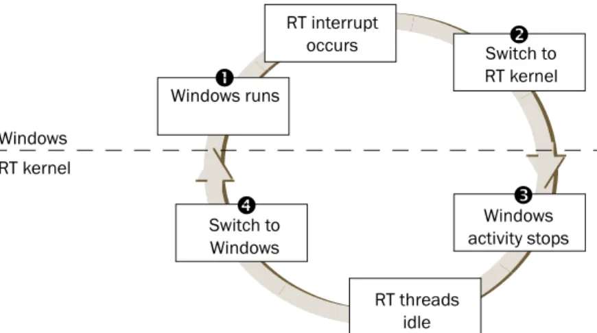
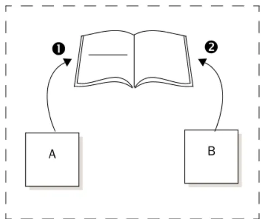
When both the Windows and RT portions of an INtime application run on a single CPU hardware thread, INtime software transfers control between the Windows and RT environments as shown in this figure:
When running on a single microprocessor, the INtime runtime environment encapsulates all Windows processes and threads into a single RT thread of lowest priority.As a result, RT threads always preempt running Windowsthreads, guaranteeing determinism for RT activities within the system.
The RT and Windows threads can share sections of memory allocated by INtime applications. A Windows thread can obtain a handle for this shared memory, then map the memory referenced by that handle into the thread’s address space.
This INtime operating environment is referred to as Shared Mode. RT interrupt occurs Switch to RT kernel RT threads idle RT kernel Windows Windows activity stops Windows runs Switch to Windows
n
o
p
q
n) When a Windows thread runs, the full Windows environment exists, including its interrupts, interrupt masks, and handlers.
o) When an RT interrupt occurs, control immediately switches to the RT kernel, where an RT interrupt handler deals with the event. This, in turn, may cause one or more RT threads to execute.
p) Windows processes and interrupts stop until the RT threads complete.
q) When all RT threads complete their work, leaving no RT threads ready to run, control switches back to the Windows environment, and standard Windows scheduling resumes.
Figure 1-2. Transferring control between Windows and INtime software’s RT kernel
Note
For detailed information about memory usage, go to INtime Help and select About INtime software, RT kernel objects, then Memory Management.
Considerations for INtime applications running on a multiprocessor PC
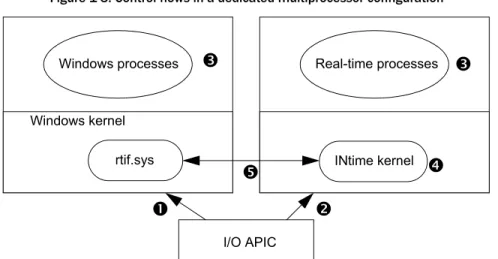
When Windows and INtime run on a multiprocessor PC, by default the INtime kernel and Windows share one CPU and Windows uses the others. The shared hardware thread behaves in the same way as the previously mentioned single-CPU case. INtime software may alternatively be configured such that an entire CPU hardware thread may be dedicated to the INtime kernel. In this case the architecture is rather different, as shown in this figure:
On multiple processors configured so that INtime has a dedicated processor, the RT kernel does not need to encapsulate the Windows system in the same way because
Figure 1-3. Control flows in a dedicated multiprocessor configuration
n) When a Windows interrupt occurs, the I/O APIC delivers the interrupt to only the Windows CPU.
o) When an RT interrupt occurs, the I/O APIC delivers the interrupt to only the INtime CPU.
p) Windows processes are never preempted by real-time interrupts and processes and vice-versa, because each OS has a dedicated CPU.
q) When all RT threads complete their work, leaving no RT threads ready to run, the INtime CPU executes an idle task until the next real-time interrupt occurs.
r) The Windows and INtime kernels signal using IPIs (Inter Processor Interrupt) and shared memory.
Windows processes Real-time processes Windows kernel rtif.sys I/O APIC
o
n
p
INtime kernelq
r
p
Chapter 1: Overview
Developing an INtime application
Design considerations
When designing INtime applications, you must divide the labor appropriately between Windows processes and RT processes and, to a finer degree, between the threads in each process. For the best performance, limit RT processes to performing only time-critical functions, and determine which Windows threads require the greater relative priority.
Code development
To develop an INtime application, you use Microsoft Visual Studio, including INtime wizards and Microsoft Visual Studio extensions for RT processes, a standard Windows debugger, and a Windows-based RT dynamic debugger that supports on-target
debugging of RT threads. INtime includes a debugger which integrates with the Visual Studio debugger. This integration supports the Visual Studio versions from 2005 onward.
Note
For detailed information about designing INtime applications, see Chapter 5, Designing RT applications.
Note
For detailed information about developing INtime applications, see Chapter 10, INtime application development.
When developing INtime applications with Microsoft Visual Studio, you create executable files for both RT and Windows environments as shown in this figure:
Features
Windows wizard Application source code NTX Windows Windows (.DLL and .EXE) files Windows portion Develop source code Compile source and link librariesCreate INtime executable files
Microsoft Visual Studio Figure 1-4. Creating INtime applications
Windows components RT application source code RT (.RTA and .RSL) files Real-time portion INtime wizard RT kernel Note
For detailed list of INtime software components, see Appendix D, INtime software components. For information about using these components, see Chapter 10, INtime application development.
Chapter 1: Overview
INtime software provides these wizards:
• Application wizard: develops the RT portion of INtime applications.
• Shared Library wizard: develops RT shared library (RSL is the RT equivalent to Windows DLL).
• Static Library wizard: develops an RT static library which you can link to other RT applications.
Libraries
INtime software provides interface libraries that your threads use to obtain RT kernel services. INtime software libraries include:
• Windows extension (NTX) library: Contains system calls that the Windows portion of an INtime application uses to communicate with the RT portion of the system. • Real-time (RT) application library: Contains system calls that the RT portion of an
INtime application uses to access RT kernel services such as memory management and inter-thread communication.
• Real-time (RT) DSM library: Contains system calls that implement sponsorship and dependency registration of INtime RTAs (real-time applications) with their counter-part Windows applications.
• Real-time C and C++ libraries: Contains system calls that the RT portion of an INtime application uses to access standard ANSI C and C++ functions.
• PCI library: Contains system calls that provide access to the PCI bus configuration space.
• iWin32 library: Contains system calls which emulate a subset of the Win32 API. • Windows iWin32x library: Contains system calls that the Windows portion of an
INtime application uses to access real-time objects created using the iWIn32 library.
Debuggers
You debug the Windows portion of INtime applications using the debug tools provided in Microsoft Visual Studio. To debug the RT portion of INtime applications, you use the debug tools provided with INtime software:
Note
For information about using the INtime wizards, see Chapter 10, INtime application development.
Note
For an overview of system calls included in the APIs, see Appendix A, INtime software system calls. For detailed information, including syntax and parameter values, see Help.
• Visual Studio debugger: The INtime software debug engine is integrated with the Visual Studio 2005 or later IDE to provide debugging capabilities from within Microsoft Visual Studio. This is the recommended default debug environment. • Spider debugger (SPIDER.EXE): A Windows application that provides source
level, multi-tasking debug capabilities. Spider can debug multiple RT threads simultaneously while other threads continue to run. Use the Spider debugger when you must be able to debug a thread in a process when other threads continue to run.
• System debug monitor (SDM): A command-line interface for RT applications that provides low-level, static debugging capability.
• System Debugger (SDB.RTA): An extension to SDM which provides information about RT kernel objects, threads, and processes.
You can simultaneously debug the Windows and RT portions of an INtime application.
Sample applications
INtime software contains several sample applications that you can use as examples for your own program development.
• EventMsg DLL Project: This DLL allows you to customize event messages. • INtime API Sample: This test application exercises most INtime software
system calls.
• Serial Communications Sample: This project demonstrates how to use the INtime Serial Communications library. The library and accompanying drivers allows the user to access serial devices such as the COM PC ports, RocketPort multi-channel PCI devices, and Edgeport multi-channel USB devices.
• Graphical Jitter: This application measures the minimum, maximum, and average Note
For detailed information about Spider, see Spider Help. For detailed infomration about SDM, see INtime Help. For detailed information about using SDM, access INtime Help, then select Debuggers>Low-level debugger>System Debug Monitor (SDM).
Chapter 1: Overview
applications, as well as basic classes, dynamic instantiation, operator overloading, and so on. It also shows the libraries and startup modules needed.
• TCP Sample Applications: Sample project that demonstrate TCP communications between a client and server. Client and server code is provided for INtime, and server code for Windows.
• UDP Sample Applications: Sample project that demonstrate a UDP ping-pong type application. Datagram packets are exchanged between INtime and Windows with an incrementing identifier in the payload.
• INtimeDotNet Sample Applications: Sample INtimeDotNet applications that demonstrate NTX communication via the INtime DotNet assembly.
• Fault Handling (ntrobust): This INtime application has both a Windows and an RT portion. The Windows portion allows the user to set up timing parameters that control how often a thread in the RT portion causes a hardware fault. The application demonstrates how another RT thread can detect and log the failure, delete the offending thread, and recreate it, all without affecting Windows or other RT processes.
• Floating Point Exception Handling: This simple program demonstrates floating point exception handling.
• RSL Examples: These RT programs demonstrate the creation and use of RT Shared Libraries, the RT analog for Windows DLLs.
• NTX Sample (MsgBoxDemo): This INtime application has both a Windows and a RT portion. The Windows portion looks up an RT mailbox created by the RT portion, and then waits at the mailbox. When an RT thread sends a message to the mailbox, the Windows portion displays the received data in a message box on the Windows side. RT semaphore and RT shared memory usage are also demonstrated. • Windows STOP Detection sample (STOPmgr): This sample application shows how an INtime application can detect either a Windows Crash (blue screen) or Windows Shutdown event and prevent Windows from completing its normal actions until the RT application has had a chance to do a “graceful” shutdown.
• Global Objects sample project: This project illustrates some aspects of the Global Objects feature of INtime. and how they are used.
• High-Performance Ethernet (HPE) sample project: This project illustrates the use of the HPE drivers included with INtime.
• PCAP Sample application: This project illustrates the use of the PCAP library to filter specific Ethernet packets from the network stack.
• USB Client sample: This sample application demonstrates how to use the INtime USB subsystem. It monitors a USB keyboard and prints a dump of each keystroke as it occurs.
Runtime environment
INtime’s runtime environment includes RT enhancements to Windows, memory protection, and blue screen protection. Runtime features are described in detail in the following sections.
RT enhancements to Windows
These features enable Windows and one or more instances of the RT kernel to work together in the same system:
• RT kernel: provides deterministic scheduling and execution of RT threads. • OS encapsulation mechanism (OSEM): manages the simultaneous operation and
integrity of the Windows kernel and the RT kernel where they occupy the same hardware thread.
• RTIF: Windows Driver that enables NTX interface between Windows threads and RT threads, and reserves system memory for exclusive use by each RT kernel instance. Also, in Shared Mode, intercepts certain HAL functions that ensures determinism of INtime applications running on a Windows host.
Memory protection
Note
For detailed information about these sample applications, see Chapter 10, INtime application development.
Note
For information about the RT kernel, see Chapter 3, About INtime software’s RT kernel. For information about the OSEM and HAL, see Chapter 2, Understanding INtime
Chapter 1: Overview
addresses not only between complex RT processes but between RT processes and Windows processes.
• Paging: The RT kernel uses the processor’s paging mode for virtual address translation, but does not implement demand paging. Each RT process loads into its own virtual address space, defined by a 32-bit virtual segment. Because code, data, and stack are automatically placed in non-contiguous areas of the application’s virtual memory, memory overruns are trapped as page faults.
• Virtual addressing: Since each RT process resides in a separate memory space defined by a virtual segment created by the RT Application Loader, RT processes cannot address beyond the virtual segment. This effectively partitions every RT process into its own address space.
“Blue screen” protection
On an INtime node, the RT kernel enables successful execution of RT threads even in the event of a total Windows failure, also known as a “blue screen crash.”
• Failure diversion: The RTIF driver captures Windows failures. Once captured, control transfers to the RT kernel, Windows operation suspends and RT threads continue to run, unaffected by the failure.
• Application-specific recovery: In the event of a Windows failure, your crash recovery RT threads run and you can execute an orderly shutdown of the hardware your INtime application controls.
In the event of a Windows blue screen crash, INtime software keeps running until a graceful shutdown occurs. To start INtime software again, you must first restart Windows.
2
Understanding INtime
software architecture
This chapter explains how the RT kernel works in conjunction with Windows to provide real-time functionality. It also lists and describes INtime components.
Terminology
Some commonly-used terms are described here:
• Host: A computer consisting of one or more processing elements (cores or hardware threads).
• Node: An instance of an operating system. A node may be on its own on a host, or one of several on a multi-core host, or sharing a host with Windows.
• Windows node: An instance of the Windows operating system, whether running on a single or multiple hardware threads.
• Node scope: Accessible by all processes on a given node.
• Remote node: A node other than the node where the current process is running. • Host scope: Accessible by all processes on all nodes of a given host.
• Universal scope: Accessible by all processes on all nodes. • Location: A handle which uniquely identifies a node.
How INtime software and Windows work together to run RT applications
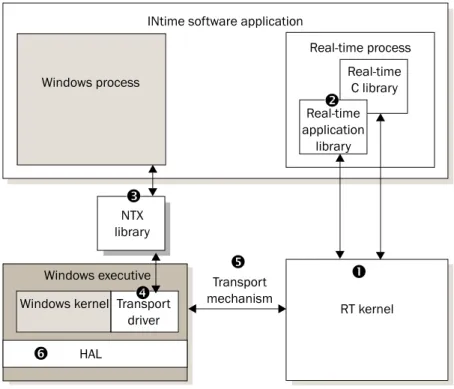
When an INtime application runs on an INtime node, Windows threads communicate with RT threads via the Windows extension (NTX) library as shown in this figure:The INtime components include:
n RT kernel: Provides deterministic scheduling and execution of RT threads within RT processes. For detailed information about the kernel, see Chapter 3, About INtime software’s RT kernel.
Real-time application, C, and C++ libraries: Gives direct access to the RT kernel Real-time C library Real-time process Windows kernel NTX library Real-time application library Windows process Transport driver Transport mechanism RT kernel HAL
INtime software application
Windows executive
Figure 2-1. How Windows threads and RT threads communicate with each other on an INtime node
n
r
s
o
p
q
Chapter 2: Understanding INtime software architecture
q Transport driver: A driver that converts information to the protocol needed by the specified transport mechanism. For details, seeTransport mechanisms later in this chapter.
r Transport mechanism: The communication protocol or method used by NTX to communicate between Windows and RT threads. Whether the various portions of your INtime applications reside on a single PC or on multiple computers accessed via Ethernet cable, NTX provides this essential communication. For details, see Transport mechanisms later in this chapter.
s Windows hardware abstraction layer (HAL): INtime software intercepts some HAL calls to ensure real-time performance. For details, seeAbout the
Windows HALlater in this chapter.
Transport mechanisms
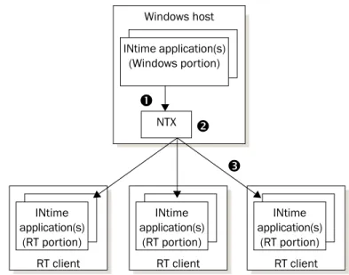
With INtime software, NTX communicates between Windows and RT portions of INtime applications, whether they reside on a single PC (single or multi-core), or on separate computers accessed via Ethernet cable:
RT client INtime application(s) (RT portion) RT client Windows host INtime application(s) (RT portion) NTX
n
o
p
nThe Windows portion of INtime applications, located on a Windows host, makes NTX calls that communicate to RT clients.
oNTX determines RT client locations, detects the connection method, and determines how to communicate between Windows and RT threads.
pNTX uses the appropriate transport method to communicate with the RT portion of the INtime applications, located on RT clients.
RT client INtime application(s) (RT portion) INtime application(s) (Windows portion)
Transport methods available to NTX include:
About the OSEM
The OSEM manages the simultaneous operation of Windows and the RT kernel on the same CPU. It encapsulates all of Windows as an RT thread, and then transparently switches execution to the appropriate kernel, based on interrupt activity and thread scheduling. Once encapsulated, Windows (with all its processes and threads) execute as a single, low priority, RT thread in the context of the RT root process.
The OSEM provides:
• Isolated processes: Uses standard Intel architecture support for hardware multi-tasking to maintain proper address space isolation and protection between Windows processes and RT processes. This approach also ensures RT
responsiveness, regardless of Windows activity.
• Transparent thread creation and switching: Transparently creates a hardware task for the RT kernel, and manages the switching and execution of both the standard Windows and INtime system hardware tasks.
In a standard Windows configuration, the bulk of the OS runs in the confines of a single hardware task. Additional hardware tasks are defined only to handle catastrophic software-induced failures, such as stack faults and double faults, where a safe and known environment is required from which to handle the failure. INtime software’s task switching approach guarantees the integrity of both
Windows and the RT kernel, and enables the successful operation of RT threads even in the event of a total Windows failure (a blue screen crash).
Transport mechanism
Transport
driver Description
OSEM RTIF.SYS Used when the Windows host and RT client co-exist on a single PC (Shared Mode). For details, see About the OSEM and How the RT interface driver works
later in this chapter.
Ethernet UDP/IP Used for Windows hosts and other INtime hosts connected via a local area network (LAN) cable.
Chapter 2: Understanding INtime software architecture
With INtime applications running on a single PC, the INtime runtime environment encapsulates all Windows processes and threads into a single RT thread of lowest priority as shown in the next figure.As a result, RT threads always preempt running Windowsthreads, guaranteeing hard determinism for all RT activities within the system.
When an interrupt occurs, the INtime runtime environment responds in one of these ways:
How the RT interface driver works
RTIF.SYS is a Windows device driver that provides centralized support for the OS encapsulation mechanism (OSEM). The RT Interface Driver facilitates communications between RT kernel threads and Windows threads.
Interrupt type Windows in control RT in control Shared control
Windows Windows maintains control. RT maintains control. RT determines whether to maintain or relinquish control.
RT RT takes control, pre-empting Windows activity.
RT maintains control. RT maintains control.
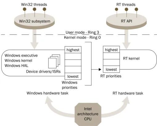
Win32 threads RT threads
Figure 2-3. Encapsulating Windows processes and threads into an RT thread
highest
RT API Win32 subsystem
Windows hardware task RT hardware task Windows executive
Windows kernel Windows HAL
Device drivers/ISRs
User mode - Ring 3 Kernel mode - Ring 0
RT kernel Intel architecture CPU lowest highest lowest Windows priorities RT priorities
The RTIF driver begins execution as a Windows system service, early in the Windows boot process. During initialization, it allocates physically contiguous memory for the RT kernel’s memory pool.
The RTIF driver cooperates with the RT Kernel Loader to load and start the RT kernel in its own environment. The driver queries the registry for various kernel parameters and passes them to the RT kernel at the kernel’s initialization time. Parameters include: • The number of Windows threads that can simultaneously make NTX library calls.
The default is 64.
• The low-level tick duration used by the RT kernel. If the RT kernel is running, the RTIF driver:
• Routes the clock interrupt (IRQ 0), based on who needs the next clock tick, to either the RT kernel or to the Windows clock interrupt entry point for processing. When neither environment needs the tick, the driver sends an EOI to the PIC for this level and returns control to the interrupted Windows thread.
• Immediately routes all other real-time interrupts to the RT kernel for processing. • Relays NTX library requests to the RT kernel and blocks the calling Windows
thread until the RT kernel responds to the request and/or until resources are available to complete the request.
Otherwise, the RTIF driver terminates NTX library requests. When the RT kernel announces its termination, the RTIF driver terminates all pending requests. • Manages the Windows portion of controlled shutdown during a Windows blue
screen crash: the handler notifies the RT kernel to handle the RT portion of the controlled shutdown. If the kernel is not running, control is returned to Windows. In summary, the RTIF.SYS device driver contains the Windows portion of the OSEM. It also acts as the NTX transport driver for a co-resident, or local, RT kernel. RTIF.SYS allocates physical memory for the RT kernel and locks that memory in place so it will not be used or paged to disk by the Windows kernel. A Windows service loads the RT kernel into the allocated memory and issues a “start kernel” command to RTIF.SYS. In response to the start command, the driver establishes a separate hardware task for the RT kernel and hands off control to the kernel’s initialization code. After initializing its
Chapter 2: Understanding INtime software architecture
• Traps attempts to assign interrupt handlers to interrupts reserved for RT kernel use. • Ensures that interrupts reserved for RT kernel use are never masked by
Windows software.
INtime software is compatible with all HAL files shipped with Windows XP and Windows 2003, and with the Multiprocessor HAL shipped with Windows Vista, Windows 7 and Server 2008.
About thread scheduling
The RT kernel switches between threads and makes sure the processor always executes the appropriate thread. The kernel’s scheduling policy is that the highest priority thread that is ready to run is/becomes the running thread. The kernel maintains an execution state and a priority for each thread and enforces its scheduling policy on every interrupt or system call.
Priority-based scheduling
A priority is an integer value from 0 (the highest priority) through 255.
Interrupt threads mask lower-priority (numerically higher) interrupt levels. When you assign interrupt levels, give a higher-priority (numerically lower) level to interrupts that can’t wait, such as serial input, and a lower priority (numerically higher) to interrupts that can wait, such as cached input.
Execution state
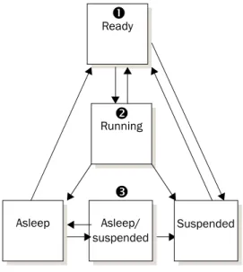
The execution state for each thread is, at any given time, either running, ready, asleep, suspended, or asleep-suspended. The RT kernel enforces the scheduling policy in which the highest priority ready thread is always the running thread.
Range Usage
0–127 Used by the OS for servicing external interrupts. Creating a thread that handles internal events here masks numerically higher interrupt levels. 128–130 Used for some system threads.
Threads run when they have the highest (numerically lowest) priority of all ready threads in the system and are ready to run. Threads can change execution state, as shown in the next figure.
nThreads are created in the ready state.
oThe running thread, the ready thread with the highest priority, does one of these: • Runs until it removes itself from the ready state by making a blocking system call. • Runs until its time slice expires (when running with a priority lower—numerically
higher—or equal to the configured round robin threshold priority with other threads at the same priority.
• Runs until preempted by a higher priority thread which has become ready due to the arrival of an interrupt, or through the receipt of a message/unit at an exchange at which the higher priority thread was blocked.
pA thread in any state except ready cannot run, even if it has the highest priority. Ready Running Asleep Asleep/ suspended Suspended
n
o
p
Chapter 2: Understanding INtime software architecture
Round-robin scheduling
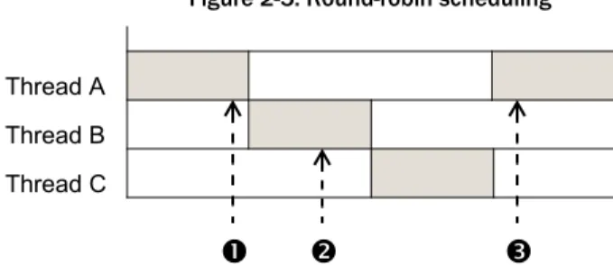
INtime software also provides round-robin scheduling, where equal-priority threads take turns running. Each thread gets a time slice. If a thread is still running when its time slice expires, that thread moves to the end of a circular queue for that priority level where it waits until all threads ahead of it use up their time slices, as shown in the next figure. You can adjust the length of the time slice and set the priority level threshold where round-robin scheduling occurs.
Higher-priority threads still preempt any running thread in the round-robin queue, regardless of the amount of time left in its time slice.
Handling interrupts
System hardware invokes an interrupt handler in response to an asynchronous interrupt from an external source, based on its entry number in the IDT (Interrupt Descriptor Table). The handler takes control immediately and saves the register contents of the running thread so it can be restarted later. There are two ways you can service an interrupt:
• Using a handler alone
• Using a handler/thread combination
Threads A, B, and C are of equal priority below the round-robin priority threshold.
nThread A, the running thread, stops running when its time slice runs out. Thread A's state is saved and it moves to the end of the queue.
oThread B, a ready thread, then becomes the running thread.
pThread A runs again when all threads in the queue either finish running or are preempted when their time slice expires.
n
o
p
Thread A Thread B Thread C
Figure 2-5. Round-robin scheduling
Note
Round-robin scheduling cannot guarantee a predictable worst-case response to events because the number of threads in the queue varies.
Interrupt handler alone
An interrupt handler alone can process only interrupts that require very little processing and time. Handlers without threads can:
• Accumulate data from the device in a buffer. The data must have an associated thread to process the data.
• A handler begins running with all interrupts disabled. It must execute quickly and then exit to minimize its effect on system interrupt latency.
• Find the interrupt level currently serviced. This is useful if one handler services several interrupt levels.
• Send an EOI (End of Interrupt) signal to the hardware.
By itself, an interrupt handler can only do very simple processing, such as sending an output instruction to a hardware port to reset the interrupt source. Handlers can use only a few system calls. For a list and description of system calls, see Appendix A, “INtime software system calls”.
During the time the interrupt handler executes, all interrupts are disabled. Since even very high level interrupts are disabled, it is essential that the handler execute quickly and exit.
When the handler finishes servicing the interrupt, it sends an EOI to the PIC (Programmable Interrupt Controller) via an INtime software system call, restores the register contents of the interrupted thread, and then returns to the interrupted thread.
Interrupt handler/thread combination
An interrupt handler/thread combination provides more flexibility. Although the handler may perform some processing, it typically signals the corresponding interrupt thread to do most or all interrupt processing. In general, use an interrupt handler/ thread combination if the processing requires more than 50 microseconds or requires system calls that interrupt handlers cannot use.
When an associated interrupt thread exists, the handler can put accumulated information into a memory address, if the interrupt thread has set one up. The interrupt thread can access data in the memory address and perform the required
Chapter 2: Understanding INtime software architecture
In addition to the usual thread activities, an interrupt thread can also: • Cancel the assignment of an interrupt handler to an interrupt level. • Wait for an interrupt to occur.
• Enable and disable interrupts.
This shows how an interrupt thread enters an eventloop where it waits to service an interrupt:
Managing time
INtime software enables threads to:
• Create alarm objects that wake up the current thread at a regular interval. • Start and stop scheduling by the RT kernel.
nUpon creation, the interrupt thread uses an RT system call to set up an RT interrupt and associate itself with this interrupt. Normally, it then waits for a signal that indicates an interrupt occured.
oWhen signaled, the interrupt thread executes the required operations.
pThe interrupt thread releases control by waiting for the next signal from the interrupt handler, which restarts the cycle shown in this figure.
Interrupt
n
o
p
3
About INtime software’s
RT kernel
This chapter describes objects provided by the RT kernel.
What does the RT kernel provide?
The RT kernel provides:
RT kernel objects
Objects, data structures that occupy memory, are building blocks that application programs manipulate. Each object type has a specific set of attributes or characteristics. Once you learn the attributes of, for example, a mailbox, you know how to use all mailboxes.
Object-based programming, which concentrates on objects and operations performed on them, is compatible with modular programming. Typically a single thread performs only a few related functions on a few objects.
The RT kernel provides basic objects and maintains the data structures that define these objects and their related system calls. When you create an object, the RT kernel returns a handle that identifies the object:
• High-level objects consume memory, but also a slot in the system GDT (Global Descriptor Table). Therefore, the maximum number of high-level objects allowed in the system at any one time is approximately 7600 (8192 slots in a GDT minus slots used by the operating system).
Item Description
Object management Includes creating, deleting, and manipulating object types defined by the kernel. Memory for high-level kernel objects is automaticallly taken from your processor’s memory pool. You must provide memory for low-level kernel objects and may allocate memory beyond the kernel’s needs to store application specific state information associated with the low-level object.
Time management Includes an RT clock, alarms that simulate timer interrupts, and the ability to put threads to sleep.
Thread management Includes scheduling locks which protect the currently running thread from being preempted.
Memory management Implements memory pools from which it allocates memory in response to application requests.
• Low-level objects consume only memory. Therefore, only the amount of system memory controls how many low-level objects can be present at a given time. The RT kernel provides these objects. Each object is discussed on the indicated page:
Threads
Threads, or threads of execution, are the active, code-executing objects in a system. Threads typically respond to external interrupts or internal events. External interrupts include events such as a keystroke, a system clock tick, or any other hardware-based event. Internal events include events such as the arrival of a message at a mailbox. Threads have both a priority and an execution state, whether the thread is running or not. There are system calls to create and delete threads, view and manipulate a thread’s priority, control thread readiness, and obtain thread handles. For a list and description of these system calls, see Appendix A, “INtime software system calls”.
Object Description Page
Threads Do the work of the system and respond to interrupts and events. 28 Processes Environments where threads do their work. 28 Exchange objects Used by threads to pass information. 32
Mailboxes Used by threads to pass objects and data. INtime software includes both object and data mailboxes.
33
Semaphores Used by threads to synchronize. 34
Regions Used by threads to provide mutual exclusion. 35 Ports Used by threads to synchronize operations, pass messages, and
access INtime services.
36 Dynamic memory Addressable blocks of memory that threads can use for any
purpose.
30
Note
For detailed information about RT kernel objects, how they operate, and system calls associated with each object, see INtime Help.
Chapter 3: About INtime software’s RT kernel
• Isolate resources for their threads, particularly for dynamically allocated memory. Two threads of one process compete for the memory associated with their process. Threads in different processes typically do not.
• Provide error boundaries. Errors within one process do not corrupt other processes or the OS because they reside in separate virtual address spaces.
• When you delete processes, the objects associated with them also are deleted. Each INtime application’s executable loads as a separate, loadable process. The processes in a system form a process tree. Each application process obtains resources from the root:
The RT Application Loader creates RT processes when an INtime application loads. There are system calls you can use to delete RT processes from within an application.
Virtual memory
Each process has an associated VSEG whose size is the amount of Virtual Memory available to the process. The VSEG size must be large enough to contain all the memory dynamically allocated by the threads within the process.
Figure 3-1. Processes in a process tree Root
process
Memory pools
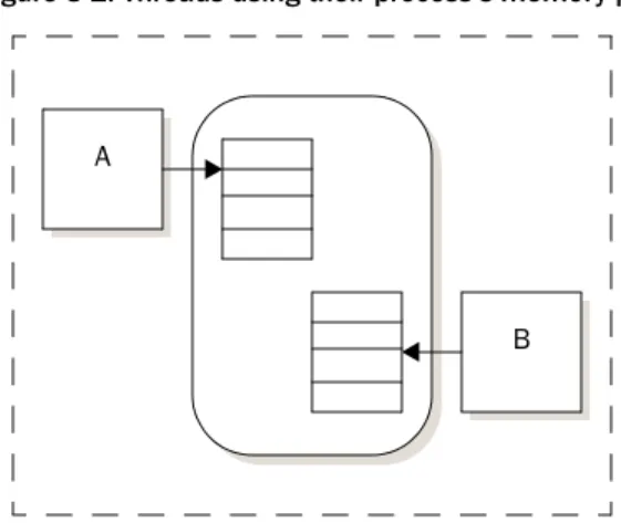
Each process has an associated memory pool, an amount of memory with a specified minimum and maximum, allocated to the process. Minimum memory is always contiguous. Usually, all memory needed for threads to create objects in the process comes from the process’s memory pool, as shown in the next figure.
If not enough contiguous memory exists (up to the maximum size of the process’s memory pool), the RT kernel tries to borrow from the root process.
You can also statically allocate memory to processes, but you cannot free memory allocated in this manner for other processes. The system’s total memory requirement is always the sum of the memory requirements of each process. Static memory allocation uses more memory than dynamic allocation, but may be safer.
Dynamic memory
Dynamic memory supports many uses, including communicating and storing data. The memory area is usually allocated from the memory pool of the thread’s process, as shown in Figure 3-2.“Threads using their process’s memory pool”. If there is not
Threads A and B obtain memory from the process’s memory pool. A
B
Chapter 3: About INtime software’s RT kernel
Object directories
Each process has an associated object directory. When a thread creates an object, the RT kernel creates a handle for it. A thread can catalog a high-level object, with its handle and a corresponding name, in the object directory of its own process or any other process it knows about. Typically, you catalog objects in the root directory so that threads in other processes can access them.
Threads that know the name can use the object directory to look up and access objects. Threads in the same process also can use global variables to identify and access objects within their process.
Note
You cannot catalog the handle for a low-level object in an object directory.
nThread A catalogs an object such as a data mailbox in the root process's object directory.
oThread B looks up the object in the object directory to use it.
Now thread A can send data to the mailbox and thread B can receive it.
A B
n
o
Exchange objects
Validation levels
INtime software provides two levels of system calls for exchange objects:
Write, test, and debug your application using high-level calls with their protection and validation features. Use low-level objects when there is no other choice, such as with AlarmEvents and a mailbox or semaphore that must be used from an interrupt handler.
Level Description Exchange objects
High (validating)
Provides higher protection and validation features.
Memory is allocated automatically from the process’s pool.
High-level objects: • Validate parameters.
• Are protected against unexpected deletion.
• Object mailboxes • Data mailboxes • Counting semaphores • Regions (for mutual
exclusion with priority inversion protection) Low
(non-validating)
Provide higher performance and lower protection and validation features. Low-level objects provide functionality beyond that of high-level objects. You must allocate memory for low-level objects and may allocate memory beyond low-level object needs. You can use this additional memory to store application-specific state information associated with the object.
Low-level objects:
• Do not validate parameters. If you need parameter validation, use high-level system calls instead.
• Are not protected against unexpected deletion. Note: System calls that manipulate low-level objects assume that all memory reference pointers received are valid.
• Data mailboxes • Single-unit semaphores • Region semaphores (with
priority inversion protection)
• Software alarm events (virtual timers) that invoke alarm event threads that you write.
Chapter 3: About INtime software’s RT kernel
Mailboxes
Mailboxes provide communication between threads in the same process or in different processes. They can send information and, since a thread may have to wait for
information before executing, they can synchronize thread execution. There are two mailbox types:
• Object mailboxes: Send and receive object handles. Available only as high level objects.
• Data mailboxes: Send and receive data. Available as both high- and low-level objects. High-level data mailboxes have a maximum message size of 128 bytes. The next figure shows how threads use an object mailbox to send a handle for a memory address.
Mailboxes have thread queues, where threads wait for messages, and message queues, where messages wait threads to receive them. The thread queue may be FIFO- or priority-based; the message queue is always FIFO-based.
You use the same system calls to create and delete object and data mailboxes. However, you use different calls to send and receive messages or data.
nThread A allocates a block of memory and creates a shared-memory handle for it. Data is placed in this shared memory object.
oThread A sends the shared memory handle to a mailbox.
pThread B waits to receive the shared memory handle at the mailbox. You can specify whether thread B should wait if the handle isn’t in the mailbox.
qThread B obtains the handle and accesses the data in the memory object by mapping the memory associated with the memory object into its memory address space.
A B
n
o
p
q
Semaphores
A semaphore is a counter that takes positive integer values. Threads use semaphores for synchronization by sending units to and receiving units from the semaphores. When a thread sends n units to a semaphore, the value of the counter increases by n; when a thread receives n units from a semaphore, the value of the counter decreases by n.
The next figure shows a typical example of a binary (one-unit) semaphore used for synchronization.
Semaphores:
• Enable synchronization; they don't enforce it. If threads do not request and obtain units from the semaphore before running, synchronization does not occur. Each thread must return the unit to the semaphore when it is no longer needed. Otherwise, threads can be permanently prevented from running.
• Provide mutual exclusion from data or a resource as follows:
To ensure that thread A can do its work before thread B starts running, thread A creates a semaphore that contains one unit. To enable synchronization, threads A and B should request and obtain the unit before running.
nThread A begins to run and obtains the semaphore unit, leaving the semaphore empty. While the semaphore has no units, thread B cannot run.
oWhen thread A completes, it returns the unit to the semaphore. Thread B can now obtain the unit and start running.
A
B
n
o
Chapter 3: About INtime software’s RT kernel
Regions
A region is a single-unit semaphore with special suspension, deletion, and priority-adjustment features. Regions provide mutual exclusion for resources or data; only one thread may control a region at a time; only the thread in control of the region can access the resource or data protected by a region. Once a thread gains control of a region, the thread cannot be suspended or deleted until it gives up control of the region. When the running thread no longer needs access, it exits the region, which enables a waiting thread to obtain control of the region and thus access the resource or data protected by that region.
Regions have a thread queue where threads wait for access to the region. The queue may be FIFO- or priority-based.
Priority inversions
Regions also have a priority-inversion avoidance mechanism when the region’s thread queue is priority based.
Then, if a higher-priority thread tries to enter a busy region, the priority of the thread in the region is raised temporarily so that it equals the waiting thread's priority. This helps prevent priority-inversion, as shown in this example:
1. Thread A is the running thread. It is a low-priority thread with control of a region, accessing some data. The region has a priority queue. The only other thread that uses the data is thread C, a high-priority thread that is not ready to run.
2. Thread B, a medium-priority thread, becomes ready to run and preempts A.
3. Thread C becomes ready to run and preempts B. It runs until it tries to gain control of the region. Thread A's priority is raised to equal thread C's priority until thread A releases the region; then its priority returns to its initial level.
4. When thread A releases the region, thread C receives control of the region and uses the data. When thread C completes, thread B runs.
Without the priority inversion avoidance mechanism, thread B would have preempted A while A had control of the region; C would have preempted B, but would have been unable to use the data because A had control of the region.
Deadlocks
Regions require careful programming to avoid deadlock, where threads need simultaneous access to resources protected by nested regions, and one thread has control of one region while the other thread has control of another. To avoid deadlock, all threads must access nested regions in the same, arbitrary order, and release them in the same reverse order.
Ports
A port is the object which allows access to the features provided by an INtime service. A process that uses a port object can send messages through the port to the INtime service, or can receive messages through the port from the service. Other operations possible on ports include:
• Attach a heap object to the port for use by the service to store received messages. • Link ports to a sink port, allowing a single thread to service multiple ports.
Services
An INtime service is an INtime real-time application (RTA) which provides access to one or more interfaces. Each interface is associated with a service descriptor. The interface generates events which are handled by the service. A process which uses a service creates a port for access to that service. A service may support more than one port and more than one user process may use a given port. A user process
communicates with the service by sending and receiving messages via the port.
Heaps
A heap is an INtime memory object that manages the chunk of dynamic memory allocated to it. A heap can be used by multiple processes that need to share large amounts of information. For instance, a heap can be associated with a port. Data placed in memory obtained from the heap by threads in one process (the thread using a port to communicate with an INtime service) can be manipulated by threads in another process (thread within the service accessing data passed through the port to the service).
Global objects, references, and locations
An INtime system is considered to be a set of one or more nodes. Multiple nodes are connected either through shared memory (multiple processor cores on the same host) or via Ethernet. The Address of a node is described in terms of its Local Logical APIC
Chapter 3: About INtime software’s RT kernel
ID and its network address. The Location of a node is a parameter used by processes on one node to identify another node.
In the case where a multi-core host is connected to the INtime network from one node only, the requests will be forwarded to the target node by the connected node.
Node architecture
On each node a management process handles requests on behalf of remote nodes, and manages local connection objects. It is also responsible for managing objects created by other nodes, and the DSM relationships between nodes.
New Objects
Two new objects and a new object classification are defined under this specification. The Location object encapsulates information about the location of a given node and the spaces it occupies. The Reference object contains information allowing the user of its handle to use an object on a remote node using the standard APIs for an object of that type.
Location object
The Location object contains APIC ID and network address information for a given node. The handle for a location object (of type LOCATION) has Node scope, not universal scope.
Figure 3-6. Global object architecture
INtime node C INtime
node A Windows node
(one or more cores)
INtime node B Network interface Network interface INtime node D Windows + INtime host
Message bus
Ethernet