Area and Power efficient booth’s
Multipliers Based on Non-Redundant
Radix-4Signed-Digit Encoding
1R.Bheema Sankaram ,2Mr. P.Gopalaswamy
1(P.G.STUDENT) M.Tech in VLSISD ,2Assistant Professorin VLSISD
Dept. Electronics and Communication Engineering Kakinada Institute of Engineering and Technology,
Korangi,AP,INDIA Abstract— In this paper, we present a design of
pre-encoded multipliers for Digital Signal Processing applications in light of disconnected encoding of coefficients. To this broaden, the Non-Redundant radix-4 Signed-Digit (NR4SD) encoding system, which utilizes the digit values {-1, 0, +1, +2} or {-2,- 1,0,+1}, is proposed prompting to a multiplier plan with less mind boggling halfway items execution. Broad trial investigation checks that the proposed pre-encoded NR4SD multipliers, including the coefficients memory, are more region and power productive than the traditional Modified Booth plot.
Keywords—Multiplying circuits, Modified Booth encoding, Pre-Encoded multipliers, VLSI implementation.
I INTRODUCTION
Media and Digital Signal Processing (DSP) applications (e.g., Fast Fourier Transform (FFT), sound/video CoDecs) do a substantial number of augmentations with coefficients that don't change amid the execution of the application. Since the multiplier is a fundamental part to implement computationally escalated applications, its design truly influences their execution.
Steady coefficients can be encoded to contain the slightest non-zero digits utilizing the Canonic Signed Digit (CSD) representation [1]. CSD multipliers contain the least non-zero halfway items, which thusly diminishes their exchanging movement. In any case, the CSD encoding includes genuine constraints. Collapsing system [2], which diminishes silicon range by time multiplexing numerous operations into single practical
units, e.g., adders, multipliers, is not doable as the CSD-based multipliers are hard-wired to particular coefficients. In [3], a CSD-based programmable multiplier configuration was proposed for gatherings of pre-decided coefficients that share certain components. The measure of ROM used to store the gatherings of coefficients is essentially lessened and also the range and power utilization of the circuit. In any case, this multiplier configuration needs adaptability since the fractional items era unit is composed particularly for a gathering of coefficients and can't be reused for another gathering. Likewise, this technique can't be effectively stretched out
to expansive gatherings of pre-decided coefficients achieving in the meantime high proficiency.
Adjusted Booth (MB) encoding handles the previously mentioned constraints and lessens to a large portion of the quantity of fractional items coming about to diminished territory, basic deferral and power utilization. Be that as it may, a devoted encoding circuit is required and the fractional items era is more mind boggling. Kim et al. proposed a strategy like [3], for planning
proficient MB multipliers for gatherings of pre-decided coefficients with similar constraints depicted in the past passage.
The proposed NR4SD encoding plan utilizes one of the accompanying arrangements of digit qualities: {-1, 0, +1, +2} or {-2,- 1,0,+1},. Keeping in mind the end goal to cover the dynamic scope of the 2's supplement frame, all digits of the proposed representation are encoded by aside from the most huge one that is MB encoded. Utilizing the proposed encoding recipe, we pre-encode the standard coefficients and store them into a ROM in a dense shape (i.e., 2 bits for every digit). Contrasted with the pre-encoded MB multiplier in which the pre-encoded coefficients require 3 bits for every digit, the proposed NR4SD conspire decreases the memory measure. Likewise, contrasted with the MB frame, which utilizes five digit values{-2,- 1,0,+1,+2}, proposed NR4SD encoding utilizes four digit values. In this way, the NR4SD-based pre-encoded multipliers incorporate a less intricate halfway items era circuit. We investigate the proficiency of the previously mentioned pre-encoded multipliers considering the measure of the coefficients' ROM.
II Modified booth algorithm
Modified Booth (MB) is a redundant radix-4 encoding technique [6], [7]. Considering the multiplication of the
-(1)
-(2)
where b−1 = 0. Each MB digit is represented by the bits s,
one and two (Table 1). The bit s shows if the digit is negative (s=1) or positive (s=0). One shows if the absolute value of a digit equals 1 (one=1) or not (one=0). Two shows if the absolute value of a digit equals 2 (two=1) or not (two=0). Using these bits, we calculate the MB digits MB bj as follows:
-(3)
Equation (4)from the mb encoding signals
-(4)
Table 1.modified booth encoding table III Non repetitive marked digit encoding
In this area, we introduce the Non-Redundant radix-4 Signed Digit (NR4SD) encoding strategy. As in MB frame, the quantity of halfway items is decreased to half. At the point when encoding the 2's supplement number B, digits bNR-take one of four qualities: {-2,- 1,0,+1} at the NR4SD-and Bnr+ take one of four qualities {-1,0,+1,+2}at the NR4SD+. calculation, individually. Just four distinct qualities are utilized and not five as a part of MB calculation, which prompts to 0 < j < k - 2. As we have to cover the dynamic scope of the 2's supplement shape, the most critical digit is MB encoded (i.e., bMB{-2,- 1,0,+1,+2}). The NR4SD-and NR4SD+ encoding calculations are outlined in detail in Fig. 1 and 2, separately.
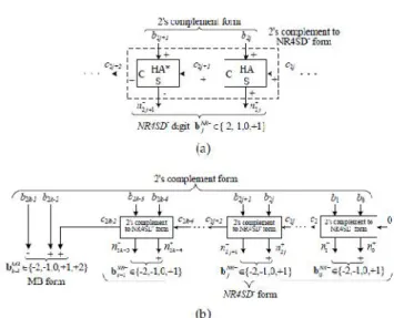
Fig.1 Block Diagram of the NR4SD- Encoding Scheme at the (a) Digit and (b) Word Level.
Fig.2 Block Diagram of the NR4SD+ Encoding Scheme at the (a) Digit and (b) Word Level.
NRS4D- algorithm
Step 1: Consider the initial values j = 0 and c0=0.
Step 2: Calculate the carry c2j+1 and the sum n+ 2j of a Half Adder (HA) with inputs b2j and c2j (Fig. 1a). Step 3: Calculate the positively signed carry c2j+2 (+) and the negatively signed sum n 2j+1 (-) of a Half Adder* (HA*) with inputs b2j+1 (+) and c2j+1 (+)
The outputs c2j+2 and n 2j+1 of the HA* relate to its inputs as follows
Step 4: Calculate the value of the bNR j digit.
-(5) Equation (5) results from the fact that n2j+1 is negatively signed and n2j+ is positively signed.
Step 5: j := j + 1.
considering the three consecutive bits to be b2k-1, b2k-2 and c2k-2 (Fig. 1b). If (j = k), stop.
Table 2 shows how the NR4SD- digits are formed. Equations (6) show how the NR4SD- encoding signals.
table.2 NRS4D- encoding.
-(6) We observe that the NR4SD�form has larger dynamic
range than the 2’s complement form.
NRS4D+ encoding
Step 1: Consider the initial values j = 0 and c0=0.
Step 2: Calculate the carry c2j+1 and the sum n+ 2j of a Half Adder (HA) with inputs b2j and c2j (Fig. 2a).
Step 3: Calculate the positively signed carry c2j+2 (+) and the negatively signed sum n 2j+1 (-) of a Half Adder* (HA*) with inputs b2j+1 (+) and c2j+1 (+)
The outputs c2j+2 and n 2j+1 of the HA* relate to its inputs as follows
Step 4: Calculate the value of the bNR j digit.
-(7) Equation (7) results from the fact that n2j+1 is negatively signed and n2j+ is positively signed.
Step 5: j := j + 1.
Step 6: If (j < k�1), go to Step 2. If (j = k�1), encode the most significant digit based on the MB algorithm and considering the three consecutive bits to be b2k-1, b2k-2 and c2k-2 (Fig. 1b). If (j = k), stop.
Table 3 shows how the NR4SD+ digits are formed. Equations (8) show how the NR4SD+ encoding signals.
Table.3 NR4SD+ encoding
As observed in the NR4SD�encoding technique, the NR4SD+ form has larger dynamic range than the 2’s complement form.
Considering the 8-bit 2’s complement number N,Table 4 exposes the limit values and two typical values of N, and presents the MB, NR4SD- and NR4SD+ digits that result when applying the corresponding encoding techniques to each value of N we considered. We added a bar above the negatively signed digits in order to distinguish them from the positively signed ones.
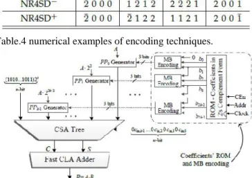
Table.4 numerical examples of encoding techniques.
Fig3.system architecture of mb multiplier. IV Pre-Encoded MB Multiplier Design
the sine table required in a FFT usage). The coefficients are encoded disconnected in light of MB or NR4SD calculations and the subsequent bits of encoding are put away in a ROM. Since our motivation is to evaluate the effectiveness of the proposed multipliers, we first present a survey of the routine MB multiplier keeping in mind the end goal to contrast it and the pre-encoded plans.
Fig.4the ROM of Pre-Encoded multipliers with standard coefficients in MB form.
In the pre-encoded MB multiplier scheme, the coefficient B is encoded off-line according to the conventional MB form (Table 1). The resulting encoding signals of B are stored in a ROM. The circled part of Fig. 3, which
contains the ROM with coefficients in 2’s complement
form and the MB encoding circuit, is now totally replaced by the ROM of Fig. 4. The MB encoding blocks of Fig. 3 are omitted. The new ROM of Fig. 5 is used to store the encoding signals of B and feed them into the partial product generators (PPj Generators - PPG) on each clock cycle. Targeting to decrease switching activity, the value
’1’ of sj in the last entry of Table 1 is replaced by ’0’. The
sign sj is now given by the relation
sj = b2j+1 _ (b2j+1 ^ b2j ^ b2j�1):
As a result, the PPG of Fig. 4a is replaced by the one of Fig. 4b. Compared to (4), (12) leads to a more complex design. However, due to the pre-encoding technique, there is no area / delay overhead at the circuit. The partial products, properly weighted, and the correction term (COR) of (11) are fed into a CSA tree. The input carry cin;j of (11) is computed as cin;j = sj based on (12) and Table 1. The CS output of the tree is finally merged by a fast CLA adder. However, the ROM width is increased. Each digit requests three encoding bits (i.e., s, two and one (Table 1)) to be stored in the ROM. Since the n-bit coefficient B needs three bits per digit when encoded in MB form, the ROM width requirement is 3n/2 bits per coefficient. Thus, the width and the overall size of the ROM are increased by 50% compared to the ROM of the conventional scheme (Fig. 3).
Fig.5generation of ppj for conventional and pre-encoded mb multiplier.
Fig.6generation of ppj for NR4SD- and NR4SD+ multiplier.
Pre-Encoded NR4SD Multipliers Design
Fig.7 system architecture of NR4SD encoding.
Fig.8 Extra Circuit Needed in the NR4SD Multipliers to Complete the (a) NR4SD�and (b) NR4SD+ Encoding.
V IMPLEMENTATION RESULTS
We implemented in Verilog the multiplier designs of Table 4. The PPGs for the NR4SD-, NR4SD+ multipliers (Fig. 5) contain a large number of inverters since all the A bits are complemented in case of a negative digit. We used Xilinx’s ise to synthesize the evaluated designs, considering the highest optimization degree and keeping the hierarchy of the designs.
Table 4.multiplier design
The below table 5 and table 6 are the synthasis results for the modified booth and non-redundant sign digit encoding minus and non redundant sign digit encoding plus for 16 and 32 bits respectively.
Mb encoding
NR4SD- NR4SD
+ NUMBER
OF SLICES
207 129 134
NUMBER OF FLIPFLOPS
11 6 6
4INPUT LUTS
364 222 230
NUMBER OF IOBS
54 54 54
Table 5.syntasis result comparison for 16 bit.
Mb encoding NR4SD- NR4
SD+
NUMBER 783 431 393
OF SLICES NUMBER
OF FLIPFLOPS
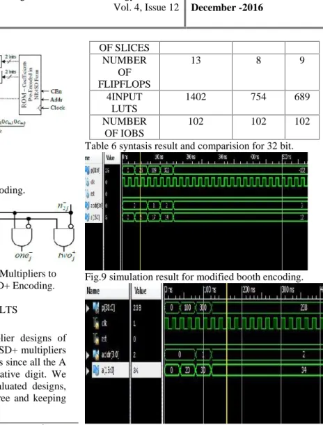
13 8 9
4INPUT LUTS
1402 754 689
NUMBER OF IOBS
102 102 102
Table 6 syntasis result and comparision for 32 bit.
Fig.9 simulation result for modified booth encoding.
Fig 10 simulation result for NRS4D-encoding
Fig9,fig10,fig11 shows the simulation result for multiplier based on modified booth encoding and non redundant signed digit encoding minus and non redundant signed digit encoding plus respectively.
Fig.11 simulation result for NRS4D+encoding. VI CONCLUSION
VII REFERENCES
[1] G. W. Reitwiesner, “Binary arithmetic,” Advances in
Computers, vol. 1, pp. 231–308, 1960.
[2] K. K. Parhi, VLSI Digital Signal Processing Systems: Design and Implementation. John Wiley & Sons, 2007. [3] K. Yong-Eun, C. Kyung-Ju, J.-G. Chung, and X.
Huang, “Csdbased programmable multiplier design for predetermined
coefficient groups,” IEICE Trans. Fundam. Electron.
Commun. Comput. Sci., vol. 93, no. 1, pp. 324–326, 2010.
[4] O. Macsorley, “High-speed arithmetic in binary
computers,” Proc. IRE, vol. 49, no. 1, pp. 67–91, Jan. 1961.
[5] W.-C. Yeh and C.-W. Jen, “High-speed booth encoded parallel multiplier design,” IEEE Trans.
Comput., vol. 49, no. 7, pp. 692–701, Jul. 2000.
[6] Z. Huang, “High-level optimization techniques for low-power multiplier design,” Ph.D. dissertation,
Department of Computer Science, University of California, Los Angeles, CA, 2003.
[7] Z. Huang and M. Ercegovac, “High-performance low-power left-to-right array multiplier design,” IEEE Trans.
Comput., vol. 54, no. 3, pp. 272–283, Mar. 2005.
[8] Y.-E. Kim, K.-J. Cho, and J.-G. Chung, “Low power
small area modified booth multiplier design for
predetermined coefficients,” IEICE Trans. Fundam. Electron. Commun. Comput. Sci., vol. E90-A, no. 3, pp. 694–697, Mar. 2007.
R.Bheema Sankaram (P.G.STUDENT) Studying M.Tech VLSISD in Kakinada Institute of Engineering and Technology, Korangi.He was awarded B.Tech degree in Electronics and Communication Engineering from Kakinada Institute of Engineering and Technology, Korangi.