Design of Printed Monopole Antenna for Wireless Energy Meter
and Smart Applications
Trushit Upadhyaya*, Arpan Desai, and Riki Patel
Abstract—European smart energy meter applications operate over a smart grid network. These applications operate over ISM frequency bands. The proposed dual-band printed monopole antenna provides a solution to smart energy meter applications. The surface dimension of the planar monopole antenna is 45×17 mm2. The antenna has strips fabricated on a standard cost-effective FR-4 substrate of thickness 1.6 mm for achieving dual-mode resonance at 868 MHz and 2.4 GHz. The proposed monopole antenna has operating impedance bandwidth of 2.89% and 2.78% for the first and second resonances, respectively. The gain of the presented antenna is in order of 1.18 dBi for lower resonant mode and 2.1 dBi for the higher resonant mode. The antenna resonates in the frequency range which is also useful in smart RFID tags for device identification operating over smart grid. In addition, the antenna can be utilized for the devices functional in Low Rate Wireless Personal Area Networks (LR-WPAN) and WiFi-based smart applications.
1. INTRODUCTION
The wireless communication technology has seen extremely rapid growth, and wireless networks play a crucial role for wireless handheld devices. The integrated antennas in such devices should be able to cater the need for acceptable gain and impedance bandwidth. Through Joint Research Center (JRC) reference report, European commission provided guidelines for conducting a cost-benefit analysis of smart grid projects. The report has convincingly argued the economic potential of the smart grid systems [1]. LR-WPAN, IEEE 802.15.4 protocol, can provide high energy efficiency and higher node-living time due to optional beacon-enable mode. Unlike Wireless LAN standard, LR-WPAN standard needs very little or negligible infrastructure for connections. There is no need of connectivity beyond the communication link established between two devices. The LR-WPAN has higher efficiency due to lower latency rates and higher node-living time. Hence, LR-WPAN offers power efficient and low cost solutions [2]. The Industrial, Scientific, and Medical (ISM) band in European countries covers a range of Low Rate Wireless Personal Area Network applications at 868.3 MHz. LR-WPAN communication applications are able to support smart grid networks with higher accuracy, lower latency and high node-living time. In addition, LR-WPAN configured for wireless sensor networks has higher power efficiency than simple sensor nets [3]. Printed monopole antennas are being extensively utilized for handheld communication devices such as tablet, laptops and mobile phones [4–8]. The printed monopole antenna operational at multiple resonant modes is being excessively utilized as embedded antennas in handheld devices for end-user applications. The antennas can be tuned for target applications without major modifications in substrate dimensions or effective antenna size. The resonant modes can be excited by modification or addition of monopole branches. The electrical size of such an antenna is always of great concern. The loop antennas etched on substrate or base of handheld devices offer an
Received 22 April 2018, Accepted 31 May 2018, Scheduled 21 June 2018
* Corresponding author: Trushit Upadhyaya ([email protected]).
28 Upadhyaya, Desai, and Patel
excellent option to monopole antennas. Such antennas are quite popular type of printed circuit board antennas for handheld devices [9–12]. Planar Inverted-F Antennas (PIFA) has also shown usefulness in tablet and mobile communications [13, 14]. The traditional PIFA, however, suffers from problems of high space requirement, structural complexity, and coupling with the base substrate. The electrically compact antenna can also be utilized for such applications, but they have low gain to support target applications [15–17]. The compactness of antenna can also be achieved by inducting lumped circuit elements. The fabrication of such antennas is complex and sometimes an inefficient process [18, 19]. The electrical size of an antenna is a vital parameter. There are many miniaturization techniques available in the literature. The left-handed materials, also known as metamaterials, offer miniaturization of the antenna [20]. The presented design can incorporate utilization of μ-negative materials such as split ring resonators in the ground plane for size reduction. The proposed dual-band antenna is configured to support designated European ISM RF links. It supports one channel of 600 kHz at 868 MHz and multiple channels in 2.4 GHz spectrum for smart energy meter and smart grid applications.
2. ANTENNA CONFIGURATION AND DESIGN CONSIDERATIONS
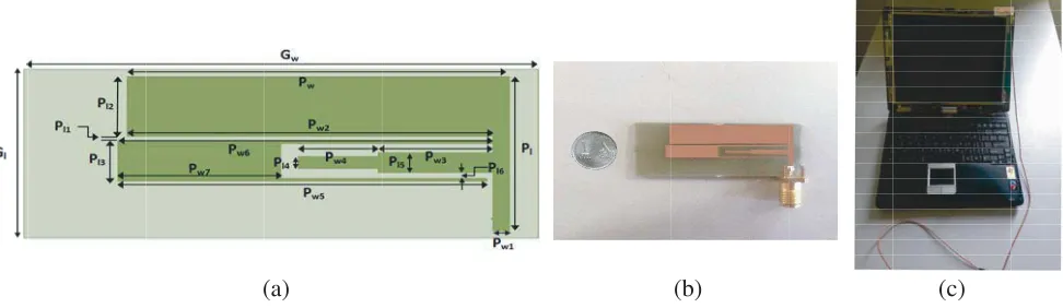
The proposed antenna geometry is depicted in Figure 1. The dimensions of the substrate are 45×17 mm2, and substrate thickness is 1.6 mm. The cost-effective FR-4 substrate was utilized for fabrication, which has an effective relative permittivity of 4.4 and loss tangent of 0.02. This high loss tangent decreases the gain of the antenna resonating in GHz regime; however, for resonance below 1 GHz, dielectric losses are relatively less. The antenna is fed through offset microstrip feed line matched at 50 Ω. The offset feed is utilized to improve the impedance matching of the antenna for improving radiation characteristics. The fringing fields induced from the planar antenna has dependence on the location of the feed line. The optimized feed location shall improve impedance matching of the planar resonator with the feed. The reflection coefficient shall, in turn, get improved with the enhancement in the impedance matching. The proposed design presents the engineered feed location to improve radiation properties of the antenna. The antenna has three strips for achieving dual resonances. Antenna ground plane has equal dimensions to that of the substrate. Entire ground plane is kept conductive to achieve the required impedance bandwidth. There is an ample space on the dielectric base to add further monopole resonators for multiband operations. However, the addition of another resonator shall induce significant mutual coupling effect. The gap between the monopole strips can be further utilized for antenna tuning for other short-range communication applications.
(a) (b) (c)
Figure 1. Antenna geometry. (a) Top view. (b) Fabricated prototype. (c) Laptop mounting.
3. RESULT AND DISCUSSIONS
Figure 2. Antenna return loss.
The measured Voltage Standing Wave Ratio (VSWR) of the antenna is better than required 3 : 1 ratio and near ideal 2 : 1 ratio for integrated antennas of wireless short-range communication devices. Antenna output parameters are tabulated in Table 1. The antenna has resonances at 868 MHz and 2.4 GHz frequencies. The discrepancies between simulated and measured results are primarily due to fabrication inaccuracies. In addition, the SMA connector is connected to monopole through standard soldering technique. This causes impedance mismatch. The impedance bandwidth of the proposed antenna is 2.89% and 2.78% which is sufficient to cover the target applications of smart grids connected in a mesh network. The open-ended slots design of the antenna provides further opportunities for bandwidth enhancement. The small gaps between the monopole strips aid in fine antenna tuning for meeting the target application requirements. The gain of the antenna is 1.18 dBi and 2.1 dBi at 868 MHz and 2.4 GHz, respectively. These values of antenna gain meet the requirement of smart energy meter. The antenna was mounted on a mini-laptop computer for measuring the operational effectiveness. The designated dimensions, all in mm, are: Gw= 45, Gl= 17, P w = 33.5,Pl= 15.5,Pw1 = 1.5,Pw2 = 32, Pw3 = 10; Pw4 = 7, Pw5 = 32.5, Pw6 = 32.8, Pw7 = 14.3, Pl1 = 0.5, Pl2 = 6, Pl3 = 4, Pl4 = 1.2, Pl5 = 1.9,Pl6= 0.65.
Table 1. Antenna parameters.
Antenna Parameters First Resonance
Simulated/Measured
Second Resonance Simulated/Measured
Frequency 868 MHz/870 MHz 2.4 GHz/2.41 GHz
Return Loss −20.58/−15.00 −17.4/−13.20
Impedance Bandwidth 2.89%/2.30 2.78%/2.70
Peak Gain 1.18 dBi/0.95 dBi 2.1 dBi/ 1.78 dBi
The current distribution of the proposed antenna is illustrated in Figure 3 which shows that current is mainly distributed near the feed line and middle part of the antenna at a lower frequency while it is concentrated near the edges of upper and lower plates of the upper patch at a higher frequency.
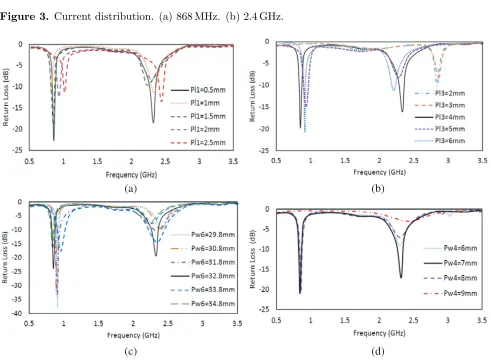
Figure 4 illustrates the return loss plots for change in the dimensions of the patch strips. The change in slot width along with strips height and width leads to shift in the frequency as well as the return loss; the optimized values of these parameters are identified after running the parametric variation. The optimum values for achieving the target frequencies with good value of return loss are P l1 = 0.5 mm,
30 Upadhyaya, Desai, and Patel
(a) (b)
Figure 3. Current distribution. (a) 868 MHz. (b) 2.4 GHz.
(a) (b)
(c) (d)
Figure 4. Parametric variation of (a)P l1, (b) P l3, (c) P w6 and (d)P w4.
various parametric analysis on the parameters which are as shown in Figures 4(a)–(d). Variation inP l1 leads to shift in the frequencies to higher side while change in the length of P l3 leads to single band characteristics instead of required dual-band characteristics at some of the values as indicated in Figure 4(b). Variations in P w6 andP w4 mainly affect the return loss values and band characteristics of the antenna.
Figure 5 illustrates antenna gain versus frequency graph. Standard gain horn antenna along with MATLAB based simulator was utilized for gain measurement. The antenna gain should be in the range of 0.5 dBi to 3 dBi for such target application. The proposed antenna satisfactorily meets the required antenna gain, which shows that it has good radiation efficiency over the ISM frequency bands.
Figure 5. Simulated (dashed) and measured (solid) antenna gain.
Figure 6. Measured return loss when it is free-standing (solid line) and when it is installed in laptop (dashed).
there would be packaging loss present. The base of laptop adds further matching loss, and coaxial cable provides further power losses. The attached antenna is still performing better than required 3 : 1 VSWR levels. Further addition of electronic components and antennas on laptop base may significantly increase the loss.
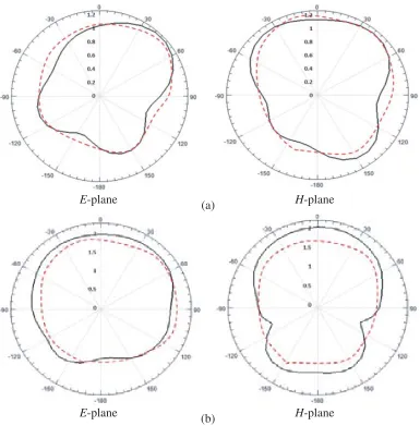
Figure 7 presents simulated and measured radiation patterns of the proposed antenna at 868 MHz and 2.4 GHz. For the resonant mode excitation at 868 MHz, there is no null present which illustrates that the antenna is quite capable to provide sufficient coverage for target smart grid applications. In
Table 2. Performance comparison of proposed antenna with literature designs.
Reference Resonant Center
Frequencies (GHz)
Efficiency (%)
Bandwidth Range (%)
Antenna Dimensions (mm2)
[8] 0.853, 2.2 60, 70 32.7, 49.7 35×10
[15] 0.852 58 28.75 45×10
[17] 0.829, 2.2 40, 56 31.60, 44.54 40×8
Proposed
32 Upadhyaya, Desai, and Patel
(a)
(b)
E-plane H-plane
E-plane H-plane
Figure 7. Simulated (solid) and measured (dashed) antenna radiation pattern. (a) 868 MHz. (b) 2.4 GHz.
the measurement for H-plane where θ is varied over omni-direction, satisfactory antenna performance is observed. The second excited mode which is responsible for 2.4 GHz resonance shows stable radiation pattern with minor null over bothEϕand Eθ. Table 2 shows the comparison of the proposed antenna with other designs available in the literature which shows that there are few designs available which resonate at 868 MHz and 2.4 GHz. The antenna presented here has high value of efficiency for the lower and higher resonance frequencies making the antenna commercially applicable to Wireless Meter and Smart Grid devices. The antenna has comparatively lower bandwidth than cited references. Further bandwidth enhancement techniques can be applied to performance improvement.
4. CONCLUSION
REFERENCES
1. European Commission 2015, Study on Cost Benefit Analysis of Smart Metering Systems in EU Member States.
2. Chen, F., N. Wang, R. German, and F. Dressler, “Performance evaluation of IEEE 802.15. 4 LR-WPAN for industrial applications,” Fifth Annual Conference on Wireless on Demand Network Systems and Services, 2008, WONS 2008, 89–96, IEEE, January 2008.
3. Callaway, E., P. Gorday, L. Hester, J. A. Gutierrez, M. Naeve, B. Heile, and V. Bahl, “Home networking with IEEE 802.15. 4: A developing standard for low-rate wireless personal area networks,” IEEE Communications Magazine, Vol. 40, No. 8, 70–77, 2002.
4. Lu, J. H. and Y. S. Wang, “Planar small-size eight-band LTE/WWAN monopole antenna for tablet computers,” IEEE Transactions on Antennas and Propagation, Vol. 62, No. 8, 4372–4377, 2014. 5. Mahatthanajatuphat, C., S. Saleekaw, P. Akkaraekthalin, and M. Krairiksh, “A rhombic patch
monopole antenna with modified Minkowski fractal geometry for UMTS, WLAN, and mobile WiMAX application,” Progress In Electromagnetics Research, Vol. 89, 57–74, 2009.
6. Ban, Y. L., S. C. Sun, J. W. Li, and W. Hu, “Compact coupled-fed wideband antenna for internal eight-band LTE/WWAN tablet computer applications,” Journal of Electromagnetic Waves and Applications, Vol. 26, No. 17–18, 2222–2233, 2012.
7. Wong, K. L. and L. C. Lee, “Multiband printed monopole slot antenna for WWAN operation in the laptop computer,”IEEE Transactions on Antennas and Propagation, Vol. 57, No. 2, 324–330, 2009.
8. Sze, J. Y. and Y. F. Wu, “A compact planar hexa-band internal antenna for mobile phone,”Progress In Electromagnetics Research, Vol. 107, 413–425, 2010.
9. Wong, K. L. and C. Y. Tsai, “Half-loop frame antenna for the LTE metal-casing tablet device,” IEEE Transactions on Antennas and Propagation, Vol. 65, No. 1, 71–81, 2017.
10. Chiu, C. W., C. H. Chang, and Y. J. Chi, “Multiband folded loop antenna for smart phones,” Progress In Electromagnetics Research, Vol. 102, 213–226, 2010.
11. Rosenberg, H., H. Jidhage, and B. Svensson, Sony Mobile Communications AB, Wideband loop antenna, U.S. Patent 7,342,539, 2008.
12. Adachi, T., A. Hirata, and T. Shiozawa, “Folded loop antennas for handset terminals at the 2.0 GHz band,” Microwave and Optical Technology Letters, Vol. 36, No. 5, 376–378, 2003.
13. Naser-Moghadasi, M., Z. Mansouri, S. Sharma, F. B. Zarrabi, and B. S. Virdee, “Low SAR PIFA antenna for wideband applications,” IETE Journal of Research, Vol. 62, No. 5, 564–570, 2016. 14. Jeon, S. and H. Kim, “Mobile terminal antenna using a planar inverted e feed structure for enhanced
impedance bandwidth,”Microwave and Optical Technology Letters, Vol. 54, No. 9, 2133–2139, 2012. 15. Lu, J. H. and F. C. Tsai, “Planar small-size LTE/WWAN tablet computer antenna with eight-band operation,” Journal of Electromagnetic Waves and Applications, Vol. 29, No. 8, 1032–1046, 2015. 16. Wong, K. L. and M. T. Chen, “Very low profile dual wideband loop antenna for LTE tablet
computer,”Microwave and Optical Technology Letters, Vol. 57, No. 1, 141–146, 2015.
17. Anguera, J., A. And´ujar, M. C. Huynh, C. Orlenius, C. Picher, and C. Puente, “Advances in antenna technology for wireless handheld devices,” Digital Communication World, Vol. 2013, No. 1921, 388–391, 2014.
18. Wong, K. L. and Y. C. Liu, “Small size WWAN tablet computer antenna with distributed and lumped parallel resonant circuits,”Microwave and Optical Technology Letters, Vol. 54, No. 6, 1348– 1353, 2012.
19. Chen, S. C. and Y. C. Tsou, “Bandwidth enhancement of a monopole exciter by using a chip-inductor-loaded shorted strip,”Journal of Electromagnetic Waves and Applications, Vol. 30, No. 11, 1481–1492, 2016.