DC Link Voltage Control For Node Interface in 3-Phase Grid
Tied Solar PVS using Adaptive Fuzzy
Chitikena Sudhesh Kumar*1,Y.Srinivasa Rao2
M.Tech(Student In Power Electronics & Drives Specialisation)1,Assistant Professor2In Department Of Electrical & Electronics Engineering
Kakinada
Institute Of Engineering And Technology-
II,Korangi,
AP,
INDIAAbstract
This paper deals with a three-organize two-orchestrate matrix tied SPV (sun powered photograph voltaic) system. The key stage is a lift converter, which fills the need of MPPT (most noteworthy power point taking after) and maintaining the evacuated sun based vitality to the DC association of the PV inverter, while the second stage is a two-level VSC (voltage source converter) filling in as PV inverter which supports control from a lift converter into the framework. The proposed structure uses a flexible DC associate voltage which is made adaptable by changing reference DC interface voltage as shown by CPI (normal reason for interconnection) voltage. The adaptable DC interface voltage control helps in the diminishment of trading influence hardships. A feed forward term for sunlight based responsibility is used to improve the dynamic response. The structure is taken a stab at considering useful lattice voltage assortments for under voltage and over voltage. The execution change is checked likely. Why since we using the feathery controller.
Keywords: Photovoltaic (PV) systems, Power quality, Fuzzy Logic Controller (FLC), Inverters, Sliding Mode Control (SMC).
I. Introduction
The cost suitability of any development is prime part for its business accomplishment. The SPV (Solar Photovoltaic) systems have been proposed long back yet the costs of sunlight based loads up have baffled the development for long time, however the SPV structures are accomplishing network balance [1], [2]. The sun oriented vitality based systems can be requested into free and matrix interfaced structures. The vitality stockpiling (generally batteries) organization is the key fragment of autonomous system. Distinctive issues related to battery vitality stockpiling free sun powered vitality change structures are analyzed in [3]–[6].
Considering the issues related with vitality stockpiling structures, the matrix interfaced systems are more perfect, incase the framework is accessible.
The matrix goes about as a vitality support, and all the made power can be energized into the network. A couple network interfaced SPV systems are proposed in past watching out for various issues related to islanding, brokenness, showing et cetera [7]–[9]. With creating power structure, the thought is moving from united period and extended dispersal to passed on time. The dispersed time can procure a couple of inclinations, for instance, diminishment in incidents, better utilization of course resources, stack profile complimenting et cetera.
The SPV systems give a better than average choice to spread time structure considering little scale time from rooftop sunlight based, measured nature of energy converter and static vitality change get ready. The fundamental enthusiasm for SPV systems is high because of high cost of sun oriented sheets [3]. Along these lines, considering the initialinvestments for any presented plant, the fact of the matter is to think most extraordinary vitality yield from as far as possible. To satisfy the objective of extraction of most outrageous vitality from a presented PV display a couple of techniques are proposed in the composition [4]–[8]. A review of MPPT (Maximum Power Point Tracking) systems is showed up in [4]. An incremental conductance (InC) based MPPT strategy is showed up in [5]. An ANN based MPPT count is showed up in [6]. The usage of sliding mode controller to MPPT estimation is showed up in [7]. A blend of fractional open circuit voltage and fleecy based MPPT technique is showed up in [8] wherein an enduring balance is incorporated at the yield of soft controller to improve the MPPT execution. The incremental conductance based MPPT is brisk, correct and easy to realize.
ostensible scope of set point for under voltage and over voltage is around 0.9 pu and 1.1 pu [9]. This range is extremely thin due to reasons, for example, converter may lose control, increment in converter rating, and converter misfortunes at low voltage and so on. If there should arise an occurrence of frail appropriation framework, a wide voltage variety is watched. Amid pinnacle stacking condition, a managed voltage plunge or under voltage is watched ordinarily. The down to earth rangeof voltage variety is about ±15% of the ostensible voltage.
The PV bolster forward term incorporates the impact of both CPI voltage variety and PV power variety. A linearised model of DC connection voltage control and impact of PV encourage forward segment on the same is likewise investigated in this paper. In the proposed framework both the info and yield voltages of DC-DC help converter are balanced continuously while keeping the target of MPPT in place. The execution of proposed control calculation is agreeable under insolation change and sudden variety of CPI voltage.
The two phase grid interfaced three stage frameworks are proposed by a few specialists, be that as it may, none of them have indicated execution for such extensive variety of CPI voltage varieties (350 V to 480 V for ostensible of 415 V). The operation of the framework for an extensive variety of CPI voltage variety builds the rating of the VSC and further the cost. Be that as it may, little augmentation in the cost of VSC can be advocated by virtue of extensive starting speculation on PV exhibit. The THD of grid current and voltages has been discovered well under IEEE-519 standard (under 5%) under every single working condition [2]. Besides, it ought to be noticed that none of the evaluations of the power gadgets are traded off in the proposed framework when contrasted with routine framework, as in both the cases the appraisals are chosen in view of most dire outcome imaginable. In this manner, the framework with proposed control approach yields more energy yield with a similar equipment assets.
II. Grid-associated VSC
The principle motivation behind this segment is to acquaint the peruser with various parts of a VSC associated with a grid. The fundamental circuit design of the VSC is exhibited so the factors and their images can be characterized and will be utilized from this time forward. Moreover, extraordinary sorts of grid channels and balance strategies will be introduced. Two control standards will be presented, the voltage edge control and the vector current control rule. At last, the demonstrating of the framework will be depicted.
Fundamental Circuit of VSC
A plan of the fundamental circuit of the VSC is appeared in Fig. 1. The valves are of the IGBTtype.
The VSC is associated with a symmetric three-stage
stack, which has the impedance R + jωL and the
emfse1(t), e2 (t) and e3 (t). The impartial purpose of the star-associated stack has the potential v0 (t), because of a skimming ground. The stage possibilities of the VSC are meant as v1(t), v2 (t) and v3(t). The stage voltages of the VSC are signified as u1(t), u2 (t) and u3(t). The present spilling out of the dc-connection to the converter is meant as iv (t) , the interface current is signified as idc (t) and the dc-connect voltage over the dc-dc-connect capacitor is indicated as udc (t) .
Figure 1: The principle circuit of the VSC. Grid Filters
While associating a VSC to a grid, an inductor must be mounted between the VSC, which is working as a firm voltage source, and the grid, which likewise works as a hardened voltage source [11]. The least difficult and most regular grid channel is the L-channel, which has three arrangement associated inductors, one in each stage. The LC-channel has a similar arrangement inductors, one in each stage, as the L-channel. Also, the LC-channel has three parallel coupled capacitors. This channel sort has regularly beeninvestigated for frameworks which are utilized as a part of self-ruling grids as a uninterruptible power supply and in many examinations, the heap comprises of resistors, one in each stage [1].
Control of the VSC Connected to the Grid
In this report, two control standards are explored for a VSC associated with a grid. They are the voltage point control and the vector current control. Both controllers utilize the turning dq-arrange framework, clarified in Appendix A. Besides, just the L-channel is considered for utilize.
Figure 2: Schematic circuit of a grid-connected VSC, where the focus is on the L-filter.
The Kirchhoff voltage law can be applied to the circuit in Figure. 2. The equation becomes
In the dq-coordinate system, the equation becomes
Where the grid angular frequency is denoted as ωg.
III. Dynamic Modeling
Over the last decade, the power engineering world is showing an increasing interest in Voltage Source Converter High Voltage Direct Current (VSC HVDC) technology. In Europe, suggestions have even been made to construct a new overlay DC grid based on VSC HVDC technology [98]. With these prospects of extending the principles of VSC HVDC to Multi-terminal (MTDC) configurations, the modeling and control of MTDC systems has become one of the more prominent research topics. This paper introduces a generic electromechanical stability model for MTDC systems with a distributed DC voltage control. The focus of the paper is on the DC system itself and not on the interconnected AC/DC system.
When modeling the MTDC system, a distinction is traditionally made based on the level of modeling detail. ElectroMagnetic Transient Programs (EMTP) accurately represent the switching dynamics and electromagnetic transients. Averaged models and electromechanical stability models have been used to study alternative outer controller structures and optimized control settings as well as dynamic interaction with the AC system and system frequency support. Power flow algorithms, as presented in, have been used to address the steady-state effects of a distributed DC voltage control.
Firstly, current and voltage limits are represented in detail in the current control loop and in the outer controller. Secondly, a cascaded control structure is introduced in the outercontroller which allows power controlling converters to take over the voltagecontrol when the DC voltage controlling converter fails.
Figure: Single phase diagram converter station AC side.
Sections respectively provide a brief overview of the converter and DC grid model and the control structure for a two-terminal VSC HVDC system. In Section this structure is extended to a MTDC system, resulting in a voltage margin approach. Section also discusses the inclusion of a voltage droop in the control structure, enabling power sharing amongst different converters in case of a converter outage. Section analyzes reduced order models and compares the results with those of the full model derived in the paper.
Converter and DC Grid Modeling
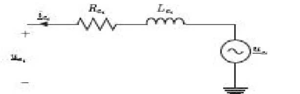
The converter can be modeled as a controllable voltage source uc behind a complex impedance Zc = Rc+|Xc connected to the Point of Common Coupling (PCC), as shown in Figure. This complex impedance comprises both the converter reactance and the transformer.
Transforming the three-phase equations to a rotating dq-reference frame and assuming the grid voltage us to be entirely oriented in the q-direction, the converter equations become
The assumption that the voltage at the PCC is entirely aligned with the q-axis comes down to neglecting the effect of the Phase-Locked Loop (PLL).
Figure: Converter model block diagram.
A first order system models the time delay caused by the processing and computation of the data and switching of the converter power electronics
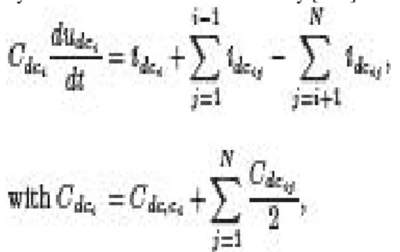
The DC lines are represented by a lumped -equivalent scheme, as depicted in FigureThe DC voltage dynamics at bus i are determined by [123]
with udci and idci respectively the DC voltage and current at bus i, Cdc,ci the converter DC capacitance, idcij the current in the branch between buses i and j and Cdcij the branch capacitance.
When the DC current dynamics are taken into account by modeling lumped inductances as shown in Figure the current dynamics of the branches connected to bus i are modeled by
Figure : DC side transient stability model.
WithRdcij and Ldcij the DC branch resistance and inductance. When the DC current dynamics are neglected, as discussed in Section, the currents are eliminated as state variables.
Two-terminal VSC HVDC Control
This section recapitulates the control of a two-terminal scheme, a full-detailed description can be found in [179]. The first part briefly summarizes the decoupled current control principles, with emphasis on the converter voltage limits. The second part discusses different outer control loops. The third part proposes an alternative implementation using a cascaded structure of an active power controller and DC voltage controllers at the two converters in order to increaseoverall redundancy.
Decoupled dq Current Control The VSC is controlled in a rotating dq-reference frame that is synchronized with the system voltage. Fig. 7.4 shows the inner current controllers, including an anti-windup (AWU). The voltage limits ucqlim and ucdlim are determined by the maximum modulation factor mmax and the DC voltage udc. The maximum converter voltage magnitude uclim can thus be written as
(a) icq current controller
(b) icd current controller
Figure Decoupled inner current controllers.
The limits can be implemented such that the controller can give priority to active or reactive power control. With the decoupling terms defined as
Redundant Outer Control
One of the disadvantages of the control implementation from the previous part,is that the control structure as such cannot cope with an outage or blockingof the DC voltage controlling converter. Whereas an outage or blocking of the power controlling converter only causes the power to drop, it does not cause a system outage since the DC voltage controlling converter can still control the DC voltage.
As the control of the DC voltage is crucial to the operation of the power system, one can therefore duplicate the DC voltage control, as proposed in [44] for the power synchronization control and mentioned in [51]. Figure shows a possiblecontrol structure for such a cascaded power control that has been developed in the framework of this paper. By implementing a correct control structure depending
on the DC voltage at the converter’s DC terminal, it
is guaranteed that only one converter at a time controls the DC voltage.
Figure: Combined active power and DC voltage controller
Voltage Margin Control
When the redundant control structure from the previous section is used in a multiterminalconfiguration, it operates as a so-called voltage margin control [125] scheme, providing a backup DC slack converter in case the main slack converter (or DC voltage controlling converter) fails. Figure shows the steady-state P-V characteristics resulting from the control implementation as observed from the DC side, thereby neglecting the converter losses. Pdclim is the active power limit resulting from the icq-limit discussed in Section / Consequently, the actual value of Pdclim depends on the voltage at the AC bus and the icqlim/icdlim ratio. The voltage margin at different converters can be determined such that different converters can take over the DC voltage control, given that only one converter at a time can control the DC voltage. Contrary to the two-terminal system, it is still possible to transfer power in case the DC slack converter fails or blocks. Figure shows simulation results for the voltage margin control implemented in the 4-terminal VSC HVDC system from Figure using MatDyn, an open-source Matlab-based transient stability program [166]. A modified Euler ODE solver was used with a step size of 2e-4 s.
The initial power flow solution from Figure, with the DC slack converter at bus 2, has been obtained using MatACDC, an open-source Matlab-based AC/DC power flow program [167]. The power flow has been initialized such that the average voltage is equal to unity. After the outage of the DC voltage controlling converter 2, converter 3 initially tries to control the converter voltage
IV. Coordinated Control of a Solar and Battery System in a Microgrid
Besides the PV and battery combined system, PV and capacitor combined system is also examined by [31, 32, 33]. Capacitors are also could be used to reduce the power actuation of PV, or participate in frequency control.
The above mentioned research work have focus on the grid-connected mode operation. The focus of this chapter is control strategies at the autonomous mode. The research was conducted on developing battery operating strategies based on a detailed battery model at both the gridconnectedand the autonomous mode.
The research results were summarized in Chapter 3. In this chapter, the research is expanded to include a PV array in the microgrid. Coordination among different DERs will be taken into consideration. A MicrogridWith a Battery, a PV Array and an Induction Generator
System Topology
The microgrid studied in this chapter consists of three DERs. An induction machine driven by a diesel engine works at the generating mode. It supplies active power to the loads within microgrid. A PV array is connected to the microgrid and supports the loads as well. A VSC interfaced battery station is included to store excess energy from the PV array or inject energy when there is a need.
Figure shows the topology of the investigated microgrid where three distribution lines are used to connect each component. The topology complies with the IEEE Standard 399-1997 [67].
Figure .System topology.
The microgrid is built in PSCAD/EMTDC with all DERs are modeled in details. The batterystation consists of two groups connected in series. Each group has an equivalent open circuit dc voltage at 4.1 kV. The maximum active power capability of which is 2MW for each group, and the energy capacity is 500kWh, which means the whole battery station could inject 4MW active power to the microgrid for 15 minutes.
The PV array consisted of many small PV panels, which could build up an open circuit dc voltage to 6 kV for the whole array. The short circuit dc current under nominal insolation level is set to 1 kA. The PV array is connected to a dc/dc converter, which is controlled by MaximumPower Point Tracking (MPPT) algorithm. A dc/ac inverter which utilizes IGBTs connects the dc/dc converter to the microgrid. PV Model
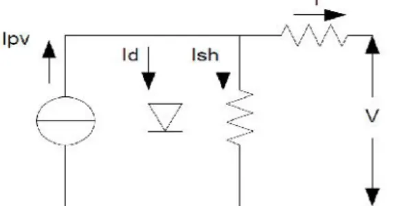
an anti-parallel diode. A parallel resistor Rsh could represent the leakage current inside the cell, and a series resistor Rs could represent the conducting loss. Figure shows a practical model of solar cell based on the introduction above.
Figure .A solar cell model.
The basic equation that represents the relationship between the solar cell current I and voltage V is given in (4.1), which implies the actual output current of a solar cell not only depends on sunlight, but also depends on output voltage and other factors. In (4.1), Ipv is the internal current generated by sunlight on solar cell, Io is the diode current, Ir is the leakage current through shuntresistor, and V and I are output voltage and current of the solar cell respectively. Some constant values used in the equations and have shown in table 4.3. The diode saturation current Io can be expressed by (4.2), where Eg is the band gap energy of semiconductor, Tn is the nominal temperature which is 298 Kelvin in this chapter. Ion is the nominal saturation current and is described by (4.3), where Isc and Voc are the short circuit current and open circuit voltage of solar cell respectively, Vt is the thermal voltage, which is described by (4.5), where Ns is the number osseries connected cells in an array. The internal current generated by sunlight of solar cell can be expressed by (4.4), where Ki is the short circuit current/temperature coecient, and G is the solar irradiation in W=m2 and Gn is the nominal solar irradiation.
Table. Parameters of solar cell
Based on (4.1) - (4.5) and the parameters shown in Table, two graphs of the relationships between current, voltage and power of solar cells could be obtained. Figure(a) shows the relationship between output current and voltage of solar cell on di erent insolation levels, whileFig. (b) shows the relationship between output power and voltage of solar cell on dierentinsolation levels. From those gures, generally, it is clear that current increases as the insolation increases, and the behavior of power has similar characteristic as well. There is one maximum power point for each insolation level, and it is desired for the operator that the maximum power could always be extracted and injected into grid. This process normally called MPPT and could be done by a dc/dc converter which will be elaborated later.
Figure. Output characteristics of PV array by varying insolation level.
System Controls
microgrid could be able to operate at the autonomous mode when such faults occur.
Since there is no synchronous generator existed in this microgrid, the voltage and frequency will be supported by VSCs. As a result, depending on the operating mode of microgrid, the VSCs could either operate at PQ control mode at grid-connected or voltage/frequency (Vf) control mode when the microgrid is at autonomous mode. The control of PV arrays involves twokinds of converters, one is dc/ac inverter, while the other is dc/dc converter. Since the active powergenerated by PV arraynormallyuctuates as sunlight or other factors changes, it is not suitable to ask the VSCs of which to operate on Vf control mode. Hence, the VSCs of PV arrays always operate on PQ control mode, which implies that the VSCs should always deliver the active power generated by PV arrays to grid, and inject the reactive power depends on the need of microgrid.
The dc/dc converter should extract the maximum power from PV arrays and send to the dc/ac inverter, which could be achieved by MPPT algorithm. Battery Control
TheThe battery control details are described PV Array Control
Figure depicts the structure of PV array and its dc/ac inverter and dc/dc converter. The dc/dc converter is a boost converter, since the nominal dc-link voltage is 15kV which is always larger than the PV array voltage. Therefore, the control system of PV array consists of two part, which is VSCs control and dc/dc converter control.
Figure .PV array and its respective converters. PQ Control
The dc/ac inverter which consists of VSCs always operates at PQ control mode. Since the active power generated by PV array depends on sunlight and temperature and is not stable as conventional energy source. The VSCs should deliver the active power eciently, otherwise the dc-link voltage between inverter and dc/dc converter will deviate from its reference value and may cause collapse.
MPPT Control
The critical control part of PV array is on dc/dc converter, which is expected to extract maximum power generated from PV array. There are several MPPT control algorithms in the literature [77, 78, 79]. The perturbation and observation (P&O) method
has been used throughout thischapter. Basically, theoperating points of reference voltage at different insolation level should beobtainedrst, which can be completed based on Figure. The reference voltages are then called vmpptref .
The control system measures the current output power of PV array and compare with the power recorded at previous step. If the current power is greater than previous one, it will compare the current output voltage with previous step. If the current voltage is larger, the reference voltage for dc/dc converter will be added by a pre-set step, which isvmppt ref + C. The other control paths are similar and just in opposite direction.
Figure depicts the duty cycle controllerof dc/dc converter. The PV output voltage reference is calculated from above P&O algorithm, and is compared with the current voltage. The error is the input of a PI controller and the respective output is the duty cycle command for dc/dc converter, which is then sent to the PWM generator.
Table. PI controller parameters of Figure
Figure. Duty cycle control of dc/dc converter
Coordinated Control
Figure shows the power coordination mechanism of the PV and the battery system. acgridvoltage and frequency are the variables to be controlled. The output real power and reactive powerof the battery system are dependent on the measured frequency error and voltage error. The total output power from the PV and the battery should meet the requirement of the microgrid.
System Evaluation in PSCAD/EMTDC
The studied microgrid is evaluated in PSCAD/EMTDC, which validates the eciency of the designed controller both on grid-connected and autonomous mode. The simulations conducted are divided into two parts: 1) First, the microgrid operates on grid-connected mode, a strong ac grid with nominal voltage at 69kV is connected to the microgrid via a 69kV/13.8kV transformer. The battery is tested both on charging and discharging mode, and the PV array is tested for fast tracking capability of insolation variations; 2) Second, a pre-assumed fault occurred and forced the main breaker opened which disconnect the grid and microgrid. After certain period that is required for the controller to detect the autonomous event, the control system switched to autonomous control mode. The voltage and frequency of microgrid are monitored, which are proved that stay at nominal value after short oscillations. Several scenarios are designed to test the control system at autonomous mode, such as load increase, load shedding and insolation variations.
System Performance at Grid-connected Mode
During the simulation, the system is working at grid-connected mode before 15s. The battery is rst charged with a ramp increased reference power that dragged from ac grid. After that, thebattery starts to work at PQ control mode, the active power output changed from injecting 0.5MW to absorbing 1MW. Meanwhile, the insolation level for the PV array changes from 1000W=m2 to 2000W=m2.
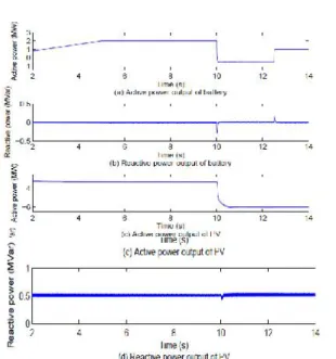
Figure shows the waveforms of system variables at such scenario. Figure (a) describes the active power output of battery, which is increased from 0 to 2MW due to the ramp charging, and the output changed from charging to injecting 0.5MW into grid at 10s, at 12.5s, the active power reference changes to absorbing 1MW. Figure shows the reactive power output of battery, which is set to 0 at grid-connected mode. In this chapter, power owing from the grid are considered positive, while owing into the grid are negative values.
The insolation level of PV is changed to test the controller of PV array and its converters. At 10s, the insolation level changes from 1000W=m2 to 2000W=m2, and Fig. demonstrates the waveform of respective active power output, which increases from 3.23MW to 6.02MW at the same time. The reactive power is set to absorbing 0.5MVar to the microgrid, which is shown in Figure.
Figure . Power outputs of battery and PV at grid-connected mode.
System Performance at Autonomous Mode
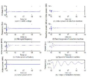
At 14.97s, a pre-set fault is triggered which opened the breaker connecting microgrid and mainac grid. This incident leads to voltage and frequency collapse since there is no synchronous generator existed in the microgrid to provide support. After 30ms [71], the controller detects the islanding event and switches to autonomous control mode. At which, the controller of the VSCs between microgrid and battery switches to Vf control, which supports the PCC voltage and system frequency. Figure shows the transient behaviors, which indicates about 1.3kV voltage sag and 3kV overshoot occurred at PCC, and the frequency devastation is less than 1.5Hz and return to60Hz after 0.5s. The active power of PV and battery system have small and short oscillations when breaker opened, and both return stable after around 0.5s.
Figure.System transient during islanding event. Insolation Variations
The insolation level varies from 2000W=m2 to almost 0W=m2 at 35s to test the capability of MPPT controller at autonomous mode. Figure(a) shows the waveform of active power from PV array, where the active power reduced from injecting 6MW to almost 0. Figure(b) shows the behaviors of battery, where the active power output of battery changes from absorbing 5MW to generating 1MW due to the loss at PV side.
The microgrid frequency stays at its nominal referencewith only less than 0.5Hz drop at that transient. Figure (d) demonstrates that SOC is increasing when absorbing power from microgrid and decreasing if injecting power. The response of induction machine is similar with the case at islanding event occurred, since the power transition of PV side is signicant.
Figure System transient during insolation variations. Load Variations
The load within microgrid may change at any time, in order to keep the power balance between load and generation, the controller should be able to handle any load change within its capability. Since the frequency is controlled by the VSCs of battery, it is expected that the battery should take the responsibility to maintain power balance within the
microgrid. Figure shows the system behaviors during load variations, in which, one load at 0.5MW and 0.25MVar is added to the microgriid at 50s, and one load at 1.3MW and 0.5MVar is disconnected from the microgrid at 70s.
Figure demonstrates that the active and reactive power of battery are regulated to corresponding value and maintain the stability. The active and reactive power of induction machine stay at its reference value, since only the VSCs of battery participates Vf control, and it is desired to not increase the induction machine output, which could save fuel as much as possible. In Figure, the microgrid frequency drops 0.1Hz at 50s due to load increase while rises 0.24Hz due to load shedding.
The induction machine runs smooth after short time oscillations corresponding load changes.
Figure .System transient during load variations.
IV. Performance Evolution
MATLAB is a high-performance language for technical computing. It integrates computation, visualization, and programming in an easy-to-use environment where problems and solutions are expressed in familiar mathematical notation. Typical uses
include- Math and computation
Algorithm development
Data acquisition
Modeling, simulation, and prototyping
Data analysis, exploration, and visualization
Scientific and engineering graphics MATLAB is an interactive system whose basic data element is an array that does not require dimensioning. This allows solving many technical computing problems, especially those with matrix and vector formulations, in a fraction of the time it would take to write a program in a scalar non-interactive language such as C or FORTRAN. The MATLAB system consists of six main parts:
This is the set of tools and facilities that help to use MATLAB functions and files. Many of these tools are graphical user interfaces. It includes the MATLAB desktop and Command Window, a command history, an editor and debugger, and browsers for viewing help, the workspace, files, and the search path.
(b) The MATLAB Mathematical Function Library
This is a vast collection of computational algorithms ranging from elementary functions, like sum, sine, cosine, and complex arithmetic, to more sophisticated functions like matrix inverse, matrix Eigen values, Bessel functions, and fast Fourier transforms.
(c)The MATLAB Language
This is a high-level matrix/array language with control flow statements, functions, data structures, input/output, and object-oriented programming features. It allows both "programming in the small" to rapidly create quick and dirty throw-away programs, and "programming in the large" to create large and complex application programs.
(d) Graphics
MATLAB has extensive facilities for displaying vectors and matrices as graphs, as well as annotating and printing these graphs. It includes high-level functions for two-dimensional and three-dimensional data visualization, image processing, animation, and presentation graphics. It also includes low-level functions that allow to fully customize the appearance of graphics as well as to build complete graphical user interfaces on MATLAB applications.
(e)The MATLAB Application Program Interface (API)
This is a library that allows writing in C and FORTRAN programs that interact with MATLAB. It includes facilities for calling routines from MATLAB (dynamic linking), calling MATLAB as a computational engine, and for reading and writing MAT-files.
(f) MATLAB Documentation
MATLAB provides extensive documentation, in both printed and online format, to help to learn about and use all of its features. It covers all the primary MATLAB features at a high level, including many examples. The MATLAB online help provides task-oriented and reference information about MATLAB features. MATLAB documentation is also available in printed form and in PDF format.
VI. Conclusion
A two-stage system has been proposed for three-phase gridconnected solar PV generation. A composite InC based MPPTalgorithm is used for control of the boost converter. The performanceof proposed system has been demonstrated for widerange of CPI voltage variation. A simple and novel adaptiveDC link voltage control approach has
been proposed for controlof grid tied VSC. The DC link voltage is made adaptivewith respect to CPI voltage which helps in reduction of lossesin the system. Moreover, a PV array feed forward term is usedwhich helps in fast dynamic response. An approximate linearmodel of DC link voltage control loop has been developed andanalyzed considering feed forward compensation. The PV arrayfeed forward term is so selected that it is to accommodate forchange in PV power as well as for CPI voltage variation. Afull voltage and considerable power level prototype has verifiedthe proposed concept. The concept of adaptive DC link voltage
REFERENCES
[1] M. Pavan and V. Lughi, “Grid parity in the Italian commercial and industrial electricity market,” in
Proc. Int. Conf. Clean Elect. Power (ICCEP’13),
2013, pp. 332–335.
[2] M. Delfanti, V. Olivieri, B. Erkut, and G. A.
Turturro, “Reaching PV grid parity: LCOE analysis for the Italian framework,” in Proc. 22nd Int. Conf. Exhib. Elect. Distrib. (CIRED’13), 2013, pp. 1–4.
[3] H.Wang and D. Zhang, “The stand-alone PV
generation system with parallel battery charger,” in Proc. Int. Conf. Elect. Control Eng. (ICECE’10),
2010, pp. 4450–4453.
[4] M. Kolhe, “Techno-economic optimum sizing of a stand-alone solar photovoltaic system,” IEEE
Trans. Energy Convers., vol. 24, no. 2, pp. 511–519, Jun. 2009.
[5] D. Debnath and K. Chatterjee, “A two stage solar
photovoltaic based stand alone scheme having battery
as energy storage element for rural deployment,”
IEEE Trans. Ind. Electron., vol. 62, no. 7, pp. 4148–
4157, Jul. 2015.
[6] S. Krithiga and N. G. AmmasaiGounden, “Power
electronic configuration for the operation of PV system in combined grid-connected and stand-alone
modes,” IET Power Electron., vol. 7, no. 3, pp. 640–
647, 2014.
[7] I. J. Balaguer-Álvarez and E. I. Ortiz-Rivera,
“Survey of distributed generation islanding detection methods,” IEEE Latin Amer. Trans., vol. 8, no. 5, pp.
565–570, Sep. 2010.
[8] C. A. Hill, M. C. Such, D. Chen, J. Gonzalez, and W. M. Grady, “Battery energy storage for enabling integration of distributed solar power generation,”
IEEE Trans. Smart Grid, vol. 3, no. 2, pp. 850–857, Jun. 2012.
[9] W. Xiao, F. F. Edwin, G. Spagnuolo, and J.
Jatskevich, “Efficient approaches for modeling and
simulating photovoltaic power systems,” IEEE J.
Photovoltaics, vol. 3, no. 1, pp. 500–508, Jan. 2013.
[10] P. Chiradeja, “Benefit of distributed generation: A line loss reduction analysis,” in Proc. IEEE/PES