Computational Investigation of Effect of
Plenum Chamber Intake over Temperature
of Liquid Flow through Nozzle
Pandiaraj.V.
Thermal Engineering
RVS College of Engineering and Technology Coimbatore, Tamilnadu, India
Titus.R
Assistant Professor, Department of Mechanical Engineering RVS College of Engineering and Technology
Coimbatore, Tamilnadu, India
Abstract - A plenum chamber is a pressurized housing containing a fluid at positive pressure (pressure higher than surroundings). One function of the plenum is to equalize pressure for more even distribution. It is used in many applications like acoustic silencer. One of the plenum chamber applications is nozzle intake which is used to reduce nozzle intake loss. Inlet pressure loss is reduced by plenum chamber. It slows down the fluid come into it and supplies nozzle with nearly stagnate condition. It will improve nozzle efficiency. In case of hot liquid flows, another parameter temperature needed to be considered. In present work, comparison of temperature changes with plenum and without plenum is proposed. Nozzle is simulated with and without plenum chamber intake for different inlet pressure of hot water. Pressure and temperature at inlet and outlet is compared for both configurations to explore effect of plenum chamber over temperature of hot liquid flow. With plenum chamber configuration computational results are again compared with experimental results.
Index Terms – Liquid Flow, Nozzle Efficiency, Plenum Chamber, Pressure Loss, Temperature.
1. INTRODUCTION
Fluid flow in circular and noncircular pipes is commonly encountered in practice. The hot and cold water that we use in our homes is pumped through pipes. Water in a city is distributed by extensive piping networks. Oil and natural gas are transported hundreds of miles by large pipelines. Fluid flow is classified as external and internal, depending on whether the fluid is forced to flow over a surface or in a conduit. Internal and external flows exhibit very different characteristics. The fluid velocity in a pipe changes from zero at the surface because of the no-slip condition to a maximum at the pipe centre.
In fluid dynamics, turbulence or turbulent flow is a flow regime characterized by chaotic property changes. This includes low momentum diffusion, high momentum convection, and rapid variation of pressure and velocity in space and time [1]. When flow is turbulent, particles exhibit additional transverse motion which enhances the rate of energy and momentum exchange between them thus increasing the heat transfer and the friction coefficient.
Computational fluid dynamics, usually abbreviated as CFD, is a branch of fluid mechanics that uses numerical methods and algorithms to solve and analyze problems that involve fluid flows [2]. The fundamental basis of almost all CFD problems are the Navier–Stokes equations, which define any single-phase (gas or liquid, but not both) fluid flow. These equations can be simplified by removing terms describing viscous actions to yield the Euler equations. Further simplification, by removing terms describing vortices yields the full potential equations [3]. Finally, for small perturbations in subsonic and supersonic flows these equations can be linearized to yield the linearized potential equations.
One of the earliest types of calculations resembling modern CFD are those by Lewis Fry Richardson, in the sense that these calculations used finite differences and divided the physical space in cells [4]. Although they failed dramatically, these calculations, together with Richardson's book "Weather prediction by numerical process", set the basis for modern CFD and numerical meteorology. In fact, early CFD calculations during the 1940s using ENIAC used methods close to those in Richardson's 1922 book.
Heat transfer describes the exchange of thermal energy, between physical systems depending on the temperature and pressure, by dissipating heat. The
fundamental modes of heat transfer are conduction or diffusion, convection and radiation [5]. Heat conduction (or thermal conduction) is the transfer of internal energy by microscopic diffusion and collisions of particles or quasi-particles within a body due to a temperature gradient.
This paper is organized as follows: Section II provides the design methodology. Section III presents the problem analysis. Section IV gives the proposed solution. The simulation results and conclusions are given in Sections V and VI respectively.
The following notations are used in this paper. The heat flux and momentum transfer (represented by the shear stress ) in the direction normal to the flow for a given time are where is the heat capacity at constant pressure, is the density of the fluid, is the coefficient of turbulent viscosity and is the turbulent thermal conductivity. Enthalpy is a thermo dynamic potential, designated by the letter "H", that is the sum of the internal energy of the system (U) plus the product of pressure (P) and volume (V).
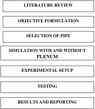
II. DESIGN METHODOLOGY
This paper considers the design methodology in Fig.1., Fig.1.2 and Fig.1.3 shows the Internal turbulent flow and External turbulent flow respectively. When flow is turbulent, particles exhibit additional transverse motion which enhances the rate of energy and momentum exchange between them thus increasing the heat transfer and the friction coefficient.
Fig.1.1 Flow Diagram of Design Methodology
Fig. 1.2. Internal turbulent flow
Fig. 1.3. External turbulent flow
Assume for a two-dimensional turbulent flow that one was able to locate a specific point in the fluid and measure the actual velocity of every particle that passed through that point at any given time. Then one would find the actual velocity fluctuating about a mean value and similarly for temperature and pressure, where the primed quantities denote fluctuations superposed to the mean.
III. PROBLEM DESCRIPTION
A plenum chamber is a pressurised housing containing a fluid at positive pressure (pressure higher than surroundings). One of plenum chamber application is nozzle intake which is used to reduce nozzle intake loss. In literatures, gain in velocity at outlet due to plenum chamber intake is studied. But no clear reviews over temperature variation in fluid at outlet are available. This is also an important consideration in case hot fluid flows.
IV. PROPOSED SOLUTON
In this work, effects of plenum intake over temperature are studied and comparison of temperature changes with plenum and without plenum is proposed. Nozzle is simulated with and without plenum chamber intake for different inlet pressure of hot water. Pressure and temperature at inlet and outlet is compared for both configurations to explore effect of plenum chamber over temperature of hot liquid flow. With plenum chamber configuration computational results are again compared with experimental
LITERATURE REVIEW
OBJECTIVE FORMULATION
SELECTION OF PIPE
SIMULATION WITH AND WITHOUT
PLENUM
EXPERIMENTAL SETUP
TESTING
results. To do this, computational and experimental investigation of nozzle intake with and without plenum chamber is proposed. Studies will be done with four inlet temperatures (30, 40, 50, 60°C) and two inlet pressures.
V. SIMULATION RESULTS Dimensions of 1 inch pipe:
Outer diameter – 1.315 inch = 33.40mm Inner diameter – 1.049 inch = 26.64mm Thickness – 0.133 inch = 3.38 mm
For experiment 0.5 hp mono block pump will be used. It is shut off pressure is 5 bar. Therefore, 3 and 4bar inlet pressures will be used to simulation and experiment. Mass flow rate is calculated as shown below.
There is a valve at pipe inlet to control flow and pressure gauge for measurement. Therefore, we can easily maintain inlet pressure as 3 and 4bar. Remaining amount of pressure in 5 bars will be converted into velocity.
TABLE 1. VELOCITY
TABLE 2. VOLUME FLOW RATE
Simulation parameters are Analysis Type, Solver and Boundary Conditions.
Simulation Results of without Plenum Chamber
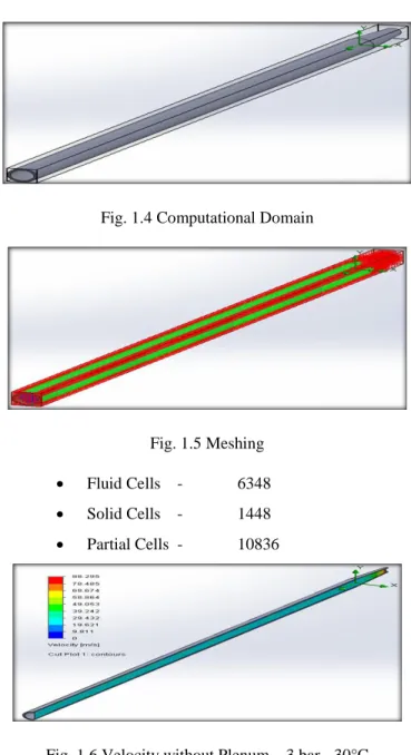
Fig. 1.4 Computational Domain
Fig. 1.5 Meshing Fluid Cells - 6348 Solid Cells - 1448 Partial Cells - 10836
Fig. 1.6 Velocity without Plenum – 3 bar - 30°C
Fig. 1.7 Temperature without Plenum – 3 bar - 30°C Remaining pressure (pa) Converted to Head, H = P / (density * g) elocity = (H * 2 * g) 0.5 200000 20.58 m 20.1 m/s 100000 10.19 m 14.14 m/s
Velocity ( m /s) Area (m2) Volume Flow Rate (m3 / s)
20.1 m/s 5.57 e-4 0.0112
Fig. 1.8 Velocity without Plenum – 3 bar - 40°C
Fig. 1.9 Temperature without Plenum – 3 bar - 40°C
Fig. 1.10 Velocity without Plenum – 3 bar - 50°C
Fig. 1.11 Temperature without Plenum – 3 bar - 50°C
Fig. 1.12 Velocity without Plenum – 3 bar - 60°C
Fig. 1.13 Temperature without Plenum – 3 bar - 60°C
Fig. 1.14 Velocity without Plenum – 4 bar - 30°C
Fig. 1.15 Temperature without Plenum – 4 bar - 30°C
Fig. 1.16 Velocity without Plenum – 4 bar - 40°C
Fig. 1.18 Velocity without Plenum – 4 bar - 50°C
Fig. 1.19 Temperature without Plenum – 4 bar - 50°C
Fig. 1.20 Velocity without Plenum – 4 bar - 60°C
Fig. 1.21 Temperature without Plenum – 4 bar - 60°C
Simulation Results of with Plenum Chamber
Fluid Cells 2688 Solid Cells 1887 Partial Cells 7891
Fig. 1.22 Computational Domain with Plenum
Fig. 1.23 Meshing of with Plenum
Fig. 1.24 Temperature with Plenum – 3 bar - 30°C
Fig. 1.25 Temperature with Plenum – 3 bar - 40°C
Fig. 1.27 Temperature with Plenum – 3 bar - 60°C
Fig. 1.28Temperature with Plenum – 4 bar - 30°C
Fig. 1.29 Temperature with Plenum – 4 bar - 40°C
Fig. 1.30 Temperature with Plenum – 4 bar - 50°C
Fig. 1.31 Temperature with Plenum – 4 bar - 60°C
Without plenum model has 1 inch pipe of 1m length with nozzle at one end and pump at other end. With plenum model has 1 inch of 800mm length, reducer of 50mm length and 2 inch diameter plenum chamber before nozzle.
VI. CONCLUSION
TABLE 3. RESULTS OF 3 BAR PRESSURE AND WITHOUT PLENUM
S.NO. Inlet Temperature (°C) Outlet Temperature (°C) 1 30 29 2 40 39 3 50 48 4 60 58
TABLE 4. RESULTS OF 4 BAR PRESSURE AND WITHOUT PLENUM
S.NO. Inlet Temperature (°C) Outlet Temperature (°C) 1 30 29 2 40 39 3 50 48 4 60 58
TABLE 5. RESULTS OF 3 BAR PRESSURE AND WITH PLENUM
S.NO. Inlet Temperature (°C) Outlet Temperature (°C) 1 30 26 2 40 36 3 50 47 4 60 57
TABLE 6. RESULTS OF 4 BAR PRESSURE AND WITH PLENUM
S.NO. Inlet Temperature (°C) Outlet Temperature (°C) 1 30 26 2 40 36 3 50 47 4 60 57
From above table, it is known that plenum chamber at nozzle inlet influences on temperature of liquid flowing through it. In straight pipes, there is no mixing in core flow stream and flow stream nearby walls, even it is turbulent flow. In plenum chamber, it is highly turbulent flow. Therefore, good mixing is happened between flow streams. In pipe flow heat transfer, temperature at wall will be less than temperature at core. In plenum chamber, mixing is happened and increases heat transfer rate. In CFD, friction is not concerned.In future, experimental investigation will be implemented.
REFERENCES
[1] Balachandran R. et. al (2005) ‘Experimental investigation of the nonlinear response ofturbulent premixed flames to imposed inlet velocity Oscillations’, Combustion and flame, 143, pg: 37–55.
[2] Gelder F.T. et. al (1971) ‘Inlet Plenum Chamber Noise Measurement Comparison of 20-Inch Diameter Fan Rotors With Aspect Ratios 3.6 And 6.6’, Nasa Technical Memorandum.
[3] Kennedy D. et. al (2011) ‘ Development Of A New Air Intake and Exhaust System For A Single Seat Race Car’, Proceedings of the ITRN2011.
[4] Mirek P. et. al (2008) ‘Numerical Optimization of Air Flow in The Plenum Chamber of An Industrial CFB Boiler’, TASK QUARTERLY, Vol 12, No 3, pg: 237–244.
[5] Nambu T. et. al (2010) ‘ Analysis and Modeling of Flow through Wind Tunnel Porous Wall’, 40th Fluid Dynamics Conference and Exhibit, AIAA 2010-4858.
[6] Nawi M.M. et. al (2013) ‘ Effect of Plenum Chamber Depth in A Swirling Fluidized Bed’, International Conference on Mechanical Engineering Research.
[7] Nawi M.M. et. al (2011) ‘ Numerical Investigate on the Centre-Bodies of Plenum Chamber in A Swirling Fluidized Bed’,IJERT, Vol 3, No 2, pg: 4-11.
[8] Othman S. et. al (2008) ‘Experimental Study of Flow in a Plenum Chamber of a Swirling Fluid Bed,Powder Technology 145. 176 – 189.
[9] Othman S. et. al (2008) ‘Numerical Study of the Plenum Chamber of a Swirling Fluidized Bed’, Proceedings of International Conference on Mechanical & Manufacturing Engineering, pg: 1-6.
[10] Zachos P.K. et. al (2011) ‘Experimental and Numerical Investigation of a Compressor Cascade at Highly Negative Incidence’, EACFM, Vol 5, Issue 1, pg: 26-36.
Mr. Pandiaraj.V. was born in Rajapalayam, India. He received his under
graduate degree in the field of Mechanical Engineering from Annamalai University, India in the year 2013. Now he is doing M.E. Thermal Engineering at RVS College of Engineering and Technology, Coimbatore, Tamilnadu, India. His research includes Thermal Storage Devices, Renewable Energy Resources, Refrigeration and Air conditioning, etc.
Mr.Titus.R. has completed his under graduate degree and post graduate degree in the department of Mechanical Engineering. Presently he is working as an Assistant Professor in RVS College of Engineering and Technology, Coimbatore, Tamilnadu, India.