Distributed Real-Time Dynamic Security Assessment
Using Intelligent Techniques
Karthik Kumar, Theodoros Kyriakidis, Maher Kayal, Rachid Cherkaoui
Electronics Laboratory & Power System GroupÉcole Polytechnique Fédérale de Lausanne CH-1015 Lausanne, Switzerland
Abstract²In real time scenario, transmission (of power) in power systems may not be always ideal i.e. they may be interrupted. As a result, the synchronization among the power generating modules may be lost. Loss of synchronization has a direct effect on the stability of power generators. Generally time domain simulation (TDS) is used to examine the stability but TDS is a time consuming process, hence we are required to explore other approaches. Accurate real-time security assessment is necessary to facilitate operations close to the stability limits. Hence for this purpose a distributed time efficient approach has been adopted to predict future values of system parameters and use the same to predict future stability of power generating modules by partially using artificial neural network and fuzzy interference system based on European Network of Transmission System Operators for Electricity (ENTSO-E) defined criteria.
Index Terms²Artificial neural networks, fuzzy logic, intelligent systems, power system stability, smart grid.
I. INTRODUCTION
The power system is the most extensive, complex and pivotal infrastructure of the modern world. Despite its importance, its structure and fundamental operating and design principles have remained unchanged for long. In the past few decades consumer load has increased at much faster pace than that of infrastructure in many nations thereby increasing operating stress of these systems. As a result, modern power systems are becoming more and more vulnerable to disturbances [1]. Recently, a plethora of factors have dictated a shift of paradigm, collectively denoted as the shift towards the smart grid. There is hardly a consensus on what really the smart grid is, or what its precise architecture is going to be [2]. Therefore, the stability of this new grid becomes a crucial consideration, and it assumes a more demanding character than its traditional form.
Power system stability is the ability of an electric power system to retain a state of operating equilibrium after being subjected to a physical disturbance, with most system variables bounded so that practically the entire system remains intact. In [3] a thorough classification of stability is provided. In this work the focus is dynamic stability. Even though the
use of the term dynamic may sometimes be ambiguous, in this work it is used to denote stability that concerns dynamic, i.e. short term phenomena. Apparently in this sense, dynamic stability concerns all three, rotor angle, frequency, and voltage stability [3].
Of course, traditional stability analysis techniques can still be applied into a smart grid concept. However there are two challenges concerning the particularities of the latter. First, the
distributed nature of the smart grid hinders the development of centralized infrastructures to process and analyze data [4]. Second, the sub-(milli-) second responsiveness/nature of the grid implies equally fast responsiveness by the analysis intelligence [2]. These factors strongly suggest the development of distributed architectures for dynamic stability analysis purposes.
This work proposes a dynamic security assessment system suited for the smart grid that is delimited by the above premises. The proposed system is distributed in nature, in the sense that it relies on local measurement data, limiting its communication requirements only during an offline stage. It monitors all three constituent parts of stability (rotor angle, frequency and voltage) using specifications set by the European Network of Transmission System Operators for Electricity (ENTSO-E). Finally, the computational core of it is established by an intelligent assessment of the input data, based on a prediction tool, an artificial neural network (ANN) and a fuzzy logic system (FLS). The speed of the latter core allows operation of the proposed system in a smart-grid real-time frame.
This paper is organized as follows. Section II introduces the reader to some fundamental background knowledge on the elements of the proposed system, and section III presents the suggested architecture. In section IV, results are presented concerning the accuracy and the computational requirements of the proposed system. Finally, conclusions are drawn in section V, and future potential research opportunities are also highlighted.
II. LITERATURE REVIEW AND FUNDAMENTALS
A. Online and Real-Time Dynamic Stability Assessment
Traditional dynamic stability assessment tools (DSA), depending on the context sometimes called transient stability assessment (TSA), have existed for decades. Traditionally they are performed offline using time-domain simulation methods to retrieve the response of the system to a disturbance. At this point it is useful to note a distinction raised in [5], between the terms online and real-time when used for power system analysis. Online refers to the results of the analysis tool being available to the Supervisory Control and Data Acquisition/ Energy Management Systems (SCADA/EMS) of the operator, while real-time refers to the results of the analysis being ready within a time frame that is deemed rational for the specific application. Real-time is particularly challenging, especially when the time constants of the volatile, inertia-poor environment of the smart grid are considered.
B. Centralized versus Decentralized
A practical drawback of the aforementioned DSA work is the need for heavy communication requirements. This is because, in all centralized structure, data from Phasor Measurement Units (PMUs) needs to be communicated through the SCADA system to central processing centers/EMS. These data are analyzed and thereof the stability of the system is assessed.
To weigh the communication requirements, in this work a
fully distributed DSA system is proposed. In distributed/decentralized structure, the intelligence is dispersed across the power system, and can function autonomously, striking out the dependency factor and communication burden contrasting to centralized architecture and thus speeding up the assessment process facilitating real-time operation. Follow up actions could be taken to eliminate or prevent large scale disturbances. The authors are not aware of similar efforts apart from [6], and with slight modifications in [7]. As it is going to be clarified in sections to follow, there is a training phase, during which communication between the autonomous intelligent modules is required. But there are no real-time requirements. To sum up, the proposed DSA system can be seen as a collection points of autonomous localized intelligence dispersed in the grid.
C. Intelligent systems
Intelligent Systems (IS) have shown encouraging potential in facilitating fast power system security assessment. Intelligent system could be defined as a system which learns during its existence and acts continually to reach its objective. ,Q ODWH ¶V, investigation with artificial intelligence (AI) in the field of security assessment was conducted. AI as well as machine learning and data mining approaches have been used to develop fast and intelligent DSA systems [8]. A thorough reference is given in [9]. As mentioned in the introduction, the computation core of the assessment procedure is based on an ANN. More specifically, it is used as rotor-angle stability prediction tool, i.e. for a given state of the system; the ANN predicts imminent rotor angle in-/stability.
Computationally, an ANN is a model of a biological neuron network [10]. It features different layers, connected by neurons that carry weights. Hidden layers map the input to the output. Training the ANN against a real system is usually done offline and it permits the ANN to recognize patterns that relate the input to the output. During its operation the ANN is able to reproduce this relation and thus, to imitate the behavior of the system it was trained against. Similar to ANN, FLS is based on nonlinear mapping of input output based on rules. FLS is unique with its ability to simultaneously handle numerical and linguistic knowledge. The rules define how the inputs are mapped onto the output. Rules are expressed in terms of IF-THEN statements [11]. The computational time of both ANN and FLS is orders of magnitude lower than that of the real system; hence, the results are available instantaneously enabling a real-time application.
III. PROPOSED IMPLEMENTATION FOR DISTRIBUTED REAL -TIME SECURITY ASSESSMENT
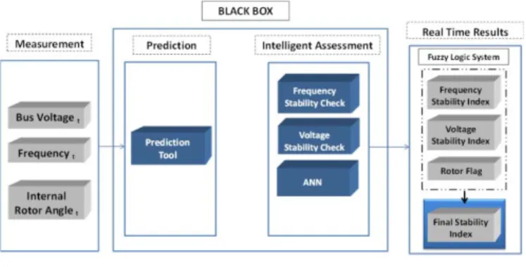
The proposed implementation as demonstrated in the block diagram (Fig. 1) has three units namely Measurement, Black Box and Real Time Results. Black Box has two inner modules and they are Prediction and Intelligent Assessment. The distributed assessment tool suggested here is to be implemented nearby each generator bus of the power system. The measurements are provided by PMUs from the generator bus. Hence the total number of distributed assessment tools to be deployed would equal the total number of generator buses.
Fig. 1. Proposed Implementation
A. Measurement
The Measurement module measures the real time value of EXVYROWDJHIUHTXHQF\DQGLQWHUQDOURWRUDQJOHįRIDpower generating module at a given time instance say t. Prediction module, as the name indicates, predicts the future value of bus voltage, frequency and internal rotor angle at time instance
t+1 using the measured values at t. A time step of ten milliseconds was used i.e. between t and t+1.
B. Prediction
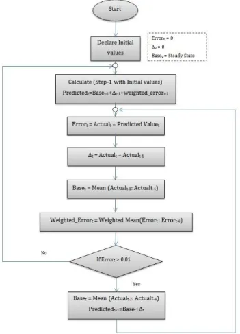
The Prediction module adapts a classical approach to predict future values. The methodology used is depicted in Fig. 2 using a flow chart. Predicted value is obtained by summing up three elements namely base, delta ǻ DQG weighted error.
Fig. 2. Flow Chart explaining Prediction Tool
Base is the average of actual values at past four time LQVWDQFHV ǻ FRUUHVSRQGV WR FKDQJH LQ DFWXDO YDOXH LQ WKH previous time step. Weighed error takes the weighted mean of error in past four time instances.
Predicted value t = Base t-1 ǻt-1 + Weighted error t-1 (1) ǻt = Actual t ± Actual t-1 (2) Error t = Actual t± Predicted Value t (3) In order to suppress overshoot/undershoot of the predicted value, a saturator has been added in the prediction loop. The saturator based upon error value at that time instance neglects the weighted error and actual value in predicted value and
base calculation respectively in the next iteration. Hence for this purpose (1) can be rewritten as
Predicted t = Base t-1 ǻt-1 (4) The prediction tool was tested using Western System Coordinated Council (WSCC) three machines, nine bus system by inflection of a perfect three phase fault. A simulation time step of 10ms was used. For Frequency, Bus voltage and Rotor angle prediction an average error of ±0.1 degree, ± 0.01 Hz and ±0.004 pu was observed respectively.
C. Intelligent Assessment
The Intelligent Assessment module has three inner functional blocks i.e. Frequency stability check, Voltage stability check and Artificial neural network (ANN). The Frequency stability check block uses the predicted value as they come in to yield the Frequency stability index. A frequency stability index ranging [0-100] is derived, based on the instantaneous deviation of the nominal operation point of f_nom = 50 Hz. The droop profile of generators is neglected in this study. This index takes into account proximity to upper and lower limits [47.5 Hz ± 51.5 Hz] as defined by ENTSO-E guidelines. For this a quadratic penalty function has been used. Around the nominal operating frequency a dead band of ± 5% is considered.
In general, the frequency of the power system has the tendency to oscillate in a non-symmetrical manner after a disturbance. Hence the index derived from these frequency values will also oscillate in similar fashion. A Butterworth low pass filter was used with a conditional case monitoring the output to filter out low amplitude high frequency variations. The crust retention is used to retain the critical low values and neglects the temporary well-thought-of values of the oscillations, as shown in Fig. 3. The cut off frequency of the filter was chosen after a detail analysis of the oscillations using Discrete Fourier Transform (DFT).
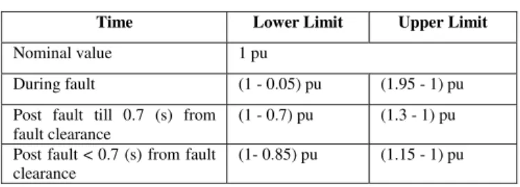
Fig. 3. Frequency Stability Index vs. Instantaneous Stability Index Analogous to Frequency stability check, Voltage stability check module produces a Voltage stability index ranging [0-100], with respect to the ENTSO-E prescribed criteria. Assuming one per unit (pu) of bus voltage as nominal value, voltage stability index reflects instantaneous deviation with respect to stability limits by means of quadratic difference function. Additionally, 5% dead band is considered around the nominal operating point. For simplicity purpose, upper limit stability criteria have been assigned symmetrically with respect to that of lower limit.
An additional function of the voltage check block is to detect the duration of the fault, by checking the profile of the variation of the bus voltage. Once the fault duration has been detected, line trip can also be determined. For most cases fault duration is detected accurately as the values change sharply when the fault is cleared. The worst case performance has been observed to be 0.1-0.2 s of overestimation of the duration
of the fault. This occurs in certain unusual scenarios, where uncommon variation of the voltage is manifested, and thus the block fails to detect accurately the duration of the fault.
TABLE I. VOLTAGE STABILITY CRITERIA
Time Lower Limit Upper Limit
Nominal value 1 pu
During fault (1 - 0.05) pu (1.95 - 1) pu Post fault till 0.7 (s) from
fault clearance
(1 - 0.7) pu (1.3 - 1) pu Post fault < 0.7 (s) from fault
clearance
(1- 0.85) pu (1.15 - 1) pu
Both Voltage and Frequency stability check blocks run in steady state as well as during contingency, whereas artificial neural network (ANN) block has a different operating profile. The ANN kicks in once fault clearance has been detected by Voltage stability check end and is used for the prediction of rotor angle stability as mentioned earlier. Rotor angle stability of generator is a relative concept, in the sense that it depends on the difference of the angle of the generator with respect to a reference.
The ANN was trained in an offline stage using a database with varied dispatch and disturbance characteristics. The output of ANN i.e. Rotor flag can be either 1 equating to stability or 0 equating to instability. In this work, the scenario was deemed stable if the angular difference between any two generators in the system always remained below 120 degrees. The ANN used here is a feed forward (Multilayer Perceptron) with back propagation. So as to reduce the complexity, the ANNs implemented are with single hidden layer (nine neurons) and were trained with seventy per cent, validated and tested with fifteen per cent of the input samples. The inputs to the ANN are the following:
x Bus Voltage Steady State (pu) x Bus Voltage Fault Clearance (pu) x Fault duration (s)
x Line Trip
x Rotor angle Steady State(rad) x Rotor angle Fault Clearance (rad) x Real Power (MW)
x Reactive Power (Mvar)
x Generator Capacity loading (%)
D. Real Time Results
So far the indexes/flag attained reflect the stability of a generator in only one of several dimensions (Rotor angle, Bus voltage & Frequency). Combining all these aspects a Final stability index was obtained. Since all these aspects are equally important the Final stability index is obtained by using a FLS as shown in Fig. 4. With the Voltage stability and the Frequency stability indices as inputs, the FLS yields the Final stability index. The input and output indexes were fuzzified using triangular membership functions with four linguistic
variables: very low (VL), low (L), high (H), very high (VH). With Voltage stability index and Frequency stability index as inputs the FLS produces Final stability index. The rules governing the mapping of FLS are tabulated in Table II. Once rotor flag is available, it is taken into account in the determination of the final index, by logical ANDing. If it is 1, the final index is calculated as explained hereinabove. If it is 0, the final index is also 0. This reflects the fact that the scenario is unstable in at least one of the constituent parts of stability, in this case the rotor angle one.
Fig. 4. Fuzzy Logic System
TABLE II. RULES FOR FLS Rule Voltage Stability
Index
Frequency
Stability Index Final Index 1 Very Low Very Low Very Low 2 Very Low Low Very Low 3 Very Low High Very Low 4 Very Low Very High Very Low 5 Low Very Low Very Low
6 Low Low Low
7 Low High Low
8 Low Very High Low
9 High Very Low Very Low
10 High Low Low
11 High High High
12 High Very High High 13 Very high Very Low Very Low
14 Very high Low Low
15 Very high High High 16 Very high Very high Very high
IV. NUMARICAL RESULTS
The proposed concept was implemented and tested using the following power systems in MATLAB.
x Western System Coordinated Council (WSCC) 9 bus, 3 machine system
x A modified version of the IEEE 57 Bus System x A 2383 version of the Polish System (winter peak) For each power generating module in a power system, a dedicated ANN was employed.
TABLE III. ANN¶S FIGURE OF MERIT
Power System Average ANN misclassification rate
WSCC 3%
Modified IEEE - 57 4% Polish 2383 WP 6.7%
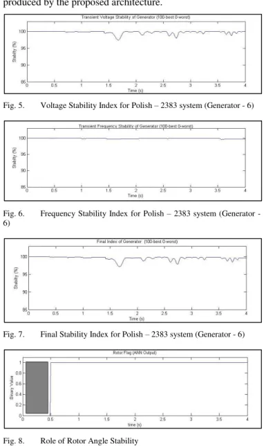
In the following, the response of the proposed DSA system to a sample fault on the polish 2383 network is demonstrated. A 400 ms perfect 3-phase fault was applied in the middle of branch #786, and Figs. 5 to 8 show the resulting indices produced by the proposed architecture.
Fig. 5. Voltage Stability Index for Polish ± 2383 system (Generator - 6)
Fig. 6. Frequency Stability Index for Polish ± 2383 system (Generator - 6)
Fig. 7. Final Stability Index for Polish ± 2383 system (Generator - 6)
Fig. 8. Role of Rotor Angle Stability
The Fig. 9 illustrates the importance of Rotor flag in the calculation. The shaded area in the graph Fig. 9 indicates the XQDYDLODELOLW\ RI $11¶V RXWSXW 5RWRU IODJ XQWLO IDXOW clearance has been detected. If Rotor flag had been zero, Final stability index would have also fallen to zero from that time instance onwards.
V. CONCLUSION
This paper proposes a novel distributed method for real time dynamic security evaluation of power systems. Its intelligence can be embedded on modules situated at buses where generators are present. The stability status of the power generating unit at each bus is predicted by processing the trajectories of variables of interest, using intelligent techniques. The scheme incorporates a forecasting tool and neural network to predict transient rotor angle stability.
Application of the method to a large 2383-bus system indicates to the fact that the proposition holds on its figure of merit despite the size of the power system it is applied upon. As a scope of future work, automated remedial action schemes (RAS) could be integrated once the indexes are at disposal. In addition, the economic value chain aspect could be explored possibly by analyzing the potential threat of power deficit on the power market in terms of monetary units.
VI. BIBLIOGRAPHY
[1] Y. Xu, Z. Y. Dong, K. Meng, R. Zhang, and K. P. Wong, "Real-time transient stability assessment model using extreme learning machine,"
IET Generation, Transmission & Distribution, vol. 5, no. 3, pp.
314-322, Mar. 2011.
[2] T. Kyriakidis and M. Kayal, "Electronics as a means of facilitating the shift towards the smart grid," Network Industries Quarterly, vol. 14, no. 2 & 3, pp. 12-15, 2012.
[3] IEEE/CIGRE joint Task Force on Stability Terms and Definitions, "Definition and classification of power system stability," IEEE
Transations on Power Systems, vol. 19, pp. 1387-1401, May 2004.
[4] A. Massoud and B. Wollenberg, "Toward a Smart Grid," IEEE Power
and Energy Magazine, vol. 3, no. 5, pp. 34-38, Oct. 2005.
[5] S. Virmani and S. C6DYXOHVFX³7KH5HDO-Time and Study-Mode
'DWD(QYLURQPHQWLQ0RGHUQ6&$'$(06´LQReal-Time Stability
Assessment in Modern Power System Control Centers, S. C. Savulescu,
Ed. Hoboken, New Jersey: Wiley, 2009, pp. 3.
[6] K. Sun, S. T. Lee, and P. Zhang, "An Adaptive Power System Equivalent for Real-Time Estimation of Stability Margin Using Phase-Plane Trajectories," Power Systems, IEEE Transactions, vol. 26, no. 2, pp. 915-923, May 2011.
[7] A. D. Rajapakse, F. Gomez, K. Nanayakkara, P. A. Crossley, and V. V. Terzija, "Rotor Angle Instability Prediction Using Post-Disturbance Voltage Trajectories," Power Systems, IEEE Transactions, vol. 25, no. 2, pp. 947-956, May 2010.
[8] L. Wehenkel, T. Van Cutsem, and M. Ribbens-Pavella, "An artificial intelligence framework for online transient stability assessment of power systems," Power Systems, IEEE Transactions, vol. 4, no. 2, pp. 789-800, May 1989.
[9] R. Zhang, Y. Xu, Z. Y. Dong, K. Meng, and Z. Xu, "Intelligent systems for power system dynamic security assessment: Review and classification," in Electric Utility Deregulation and Restructuring and
Power Technologies (DRPT), 2011 4th International Conference,
Weihai, Shandong, 2011, pp. 134-139.
[10] S. O. Haykin, Neural Networks and Learning Machines, 3rd ed. Prentice Hall, 2009, vol. 10.
[11] J. M. Mendel, "Fuzzy logic systems for engineering: a tutorial,"