Finding Total Deformation And Materials
Properties Used In Tyre Tread Under Loading
and Unloading Condition Using FEA Method
Mayank kumar sahu#1,Vishal Achwal*2, Suman Sharma#3#
PG student, Sage University Indore, *Professor Sage University Indore, #HOD Sage University Indore Mechanical Engineering Department, Sage University, Indore.
Abstract: This project aims to realize the life cycle and best tyre tread design. An important aspect is thedevelopment of robust tyre friction model to include tyre and road interaction. Grippingcharacteristic of Tyre tread plays a vital role in friction between tyre and road when loading andunloading is done quickly. Tread should be such that it provides the most grip and have operatingconstancy on road. This component is for the safety concern of the vehicles.In this project, the Tyre model will be modeled using Creo software. Then, the prepared model issimulated for rubber material and different tread pattern. Tyre model is simulated using the FiniteElement Method (FEM). FEA is used to simulate engineering problems. FEM software, ANSYSStatic Structural is used for the calculating stress and strain in tread. Static structural determinesthe displacements, stress, strains and forces in tyre caused by the loads that do not induce inertiaand damping effects. Steady loading and structure’s response are assumed to vary slowly withrespect to time. On loading conditions, the load to be assumed is 31 ton and on unloadingconditions, load is 10 ton approximately. The simulation result with lower stress and strain values isthe point of interest.
Keywords – FEA, FEM, ANSYS 1.1 Problem formulation
Heavy trucks are made for goods transportation. They are meant to travel from very bad road conditions. Truck gripping is the most important factor for smooth travelling. Actually, there are several factors that affect the road grip. Some of which are critical.
1. Truck tread design.
2. The material of the contacting surfaces, i.e. rubber quality and road surface material. 3. The texture of these materials, i.e. the
rougher texture the better road grip.
4. The force pressing the surfaces together, i.e. the weight of the vehicle.
5. Other materials between the contact surfaces, e.g. water, ice, gravel or oil spill.
In a typical driving situation, the first four factors are rather constant; our vehicle has a certain weight and certain tyres, and we drive on a long road. Accordingly, we adapt our driving style to these given factors. But all of a sudden, there could be a heavy rain, and everything changes.
Therefore, Tread of a tyre is what we cam develop on our own for better gripping on any type of road. For different tread type we will find out stress via static structural analysis on one of the best Finite Element Analysis based software, ANSYS.
1.2 Background
Tyres are the most imperative part of a vehicle which conveys the full heap of the vehicle. this task centers around the substantial truck. Fundamentally, a truck is intended to take the heap which produces least worry in the tyre. In tyre, track assumes essential job while braking. On stacking and emptying conditions, stack dissemination differs. Contingent on the pressure esteems we will ascertain the life expectancy of feel worn out on various tracks and comparing analytical results with the theoretical one.
1.3 Tyre Tread Designs
Tyres generally fall into one of the following categories:
• Directional • Non-directional
• Symmetric and Asymmetric.
Tyre have different component for different types of Tyre. Therefore, the characteristics of different tyre change accordingly.
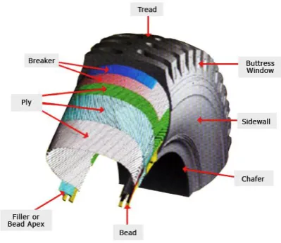
Figure 1.2: Tyre Components
1. Bead – The part of the Tyre, which is so shaped as to fit the rim and hold the Tyre on to it. It has cores made of several strands of essentially in-extensible steel wire with the end of the plies wrapped around the cores for anchorage.
2. Sidewall- The part of the Tyre between the bead and the tread, which flexes in service.
3. Tread – This is the part of the Tyre which comes in contact with the ground and through which the driving, braking and cornering forces are transmitted. It is made of a special rubber compound to give good wearing properties and in conjunction with the tread pattern to transmit these forces.
4. Ply – A layer of rubber coated fabric cords made from rubber coated fabric (Rayon, Nylon, Steel, Polyester etc.
5. Carcass – The rubber-bonded cord structure of a Tyre integral with the bead which provides the requisite strength to carry the load.
6. Breaker (Diagonal)- Intermediate rubberized fabric layers/plies between the carcass and the tread which helps bonding as well as protects the casing from road shocks.
1.5 Tyre Material
Present day Tyre are produced using a scope of materials. The elastic is for the most part manufactured, with carbon dark added to build quality and sturdiness. At the point when utilized in the track, this mix gives a long life. Normal elastic is weaker than the manufactured rendition. It's utilized
primarily in sidewalls. The employs are produced using strings of texture, covered with elastic. Producers utilize a modern determination procedure to make mixes that give the required execution attributes and 'hysteresis level' of the Tyre. Hysteresis can best be depicted as the vitality lost, for the most part as a development of warmth, when a segment of vulcanized elastic is disfigured in a normal, steady way.[1]
The more you subject a tyre to flexing and deformation the more heat will build up within the tyre. Excessive heat is the enemy of a tyre, so this builds up has to be kept under control. Therefore Rubber is selected as the tyre tread material.
1.6 Tyre Rim Material
In the car business, compound wheels will be wheels that are produced using a combination of aluminum or magnesium. Compounds are blends of a metal and different components. They by and large give more noteworthy quality over unadulterated metals, which are typically a lot milder and progressively pliable. Composites of aluminum or magnesium are normally lighter for a similar quality, give better warmth conduction, and regularly deliver enhanced restorative appearance over steel wheels. In spite of the fact that steel, the most well-known material utilized in wheel creation, is a composite of iron and carbon, the expression "amalgam wheel" is normally saved for wheels produced using nonferrous compounds.
In this manner, we are accepting Structured Steel as rim material.
LITERATURE REVIEW
Chinedum O. Mgbemena, Member, IAENG, Chika E. Mgbemena, Member, IAENG
Festus I. Ashiedu, Member, IAENG and A. R. Ravindranatha Menon.et .al
material created from Natural Rubber/Organomodified kaolin will perform well under static basic examination, as the vowsMoses pressure estimation of 1.0105MPa got on most extreme swelling is lower than the connected greatest expansion weight of 0.2206 MPa and the von Mises pressure estimation of 0.9448 MPa acquired on use of vertical heap of 5.15kN is lower than the predetermined weight on vertical stacking.[8]
Nan Xu, Konghui Guo, Xinjie Zhang, Hamid Reza Karimi
The tire mechanical characteristics under combined cornering and braking/driving situations have significant effects on vehicle directional controls. The objective of this paper is to present an analytical tire model with flexible carcass for combined slip situations, which can describe tire behavior well and can also be used for studying vehicle dynamics. The tire forces and moments come mainly from the shear stress and sliding friction at the tread-road interface. In order to describe complicated tire characteristics and tire-road friction, some key factors are considered in this model: arbitrary pressure distribution; transitional, bending, and twisting compliance of the carcass; dynamic friction coefficient; anisotropic stiffness properties. The analytical tire model can describe tire forces and moments accurately under combined slip conditions. Some important properties induced by flexible carcass can also be reflected. The structural parameters of a tire can be identified from tire measurements and the computational results using the analytical model show good agreement with test data.
METHEDOLOGY
2.1 10 R 20 16 PR Tyre Pattern
Specifications:
ATR223 is unique belt structure; high wear ability and low HBU base tread formula
Long mileage, good traction performance excellent guiding
Excellent fuel efficiency makes it suitable for high speed.
Optimized and stronger design for the tyre bead.
Suitable for top tough road conditions.
Improved radial structure offers comfort riding.
Provide less component abrasion.
Figure 1 Tyre Dimensions
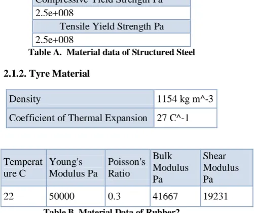
2.1.1 Rim Material
Compressive Yield Strength Pa 2.5e+008
Tensile Yield Strength Pa 2.5e+008
Table A. Material data of Structured Steel
2.1.2. Tyre Material
Density 1154 kg m^-3 Coefficient of Thermal Expansion 27 C^-1
Temperat ure C
Young's Modulus Pa
Poisson's Ratio
Bulk Modulus Pa
Shear Modulus Pa 22 50000 0.3 41667 19231
Table B. Material Data of Rubber2
2.2 Cad Model Import
The geometry is then imported for further simulation process. The geometry will be in .igs format or change to .step format for easy importing.
Pressure
Pressure in Pa will be: 1 Psi = 6894.75 Pascals 60 Psi = 60* 6894.75 Pa
= 413685 ~ 4 e+005 Pa
Figure 2: Pressure
2.2.1 Loads
Load is applied vertically downward as the whole weight of truck along with the load is acting on the 6 tyres. Load is equally distributed on each tyre. On loading conditions gross vehicle weight comes to be 31000 N.
Load acting on each tyre will be: F = 31000/ 6 N
= 5166 N ~ 5kN
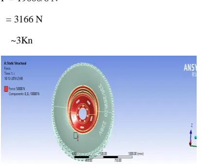
On unloading conditions, the vehicle weight will be 19000N. So load on each tyre be:
F = 19000/6 N = 3166 N
~3Kn
Figure 3: Force on loading condition
Figure 4: Force on unloading condition
the measured radial deformations of the tire demonstrate a similar trend to the simulation results when the wheel load and inflation pressure change. Measured verticle deformations with static condition 44mm and shows a dependence on the wheel load were first interpolated to N (N = 3000) equidistant
circumferential positions between -180 to 180° The mean radial deformation value Wlaser_mean, as
an indicator, is calculated as follows.
Wlaser_mean = ∑ Wlaser(φ, - 180o< φ< 180o)/ N
where Wlaser(Ф) is the interpolated radial deformation at a specific circumferential position Ф. Tension Force in the carcass = σϴo = p0bR + ƿAR2ᴒ2
= 4.13* 0.7* 0.5 + 1154 * 0.785 * (0.5)2 * (1500)2
= 510.563,125 N =510 MN Stress = Force/ Area =510/ 0.785 =649 MPa
Stress value on simulation gives lesser value when compared to theoretical one. Hence, Simulation results are acceptable.
Model Stiffness Factor =
kn = ( EIn2/R4 + σϴo / R2 )(1 – n2)2 - p0b ( 1 – n2)
/R + kv + kwn2 - ƿA (1 + n2) ᴒ2
= {1.41*4/ (0.5)4 + 2/(0.5)2(1- 4)2 - 4.13*0.16 (1- 4) /0.5 + 5.19*105 + 1.24*105*4 - 1154*0.0016 (1+4) 1002 }
CONCLUSION AND RESULT
Finite element analysis is used for investigating the stresses in the tyre tread. The 3D tyre model is modeled allowing simulation of tyre. The vertical load step provided the deflection of 3D tyre model under the applied force, as well as the distributions of contact stresses in static conditions. Distributions of contact stresses in braking and traction conditions were obtained from the steady state analyses.
Subsequently for the validation of the finite element model experimental results are to be used. Present research is done using the finite element model of the 10.00R20 16 PR of heavy duty vehicle TATA LPT 3118 tyre aims at investigating the influence of different tyre tread and construction parameters on contact patch stresses, and the consequences on the active safety of heavy vehicles.
Comparision is done for different tread pattern with the same material. Depending on loading and unloading conditions there are different stress values and deformation. On conparision, we will get the best tyre tread. Best tyre tread will give us best gripping between truck tyre and road.
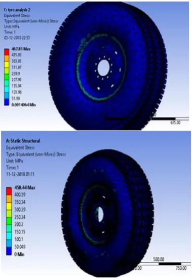
2.3 Comparision for Vonmises Stress
2.3.1 On unloading Condition
Figure 5: Comparision for vonmises stress on unloading condition
Treads Maximum Equivalent
Vonmises Stress
(MPa)
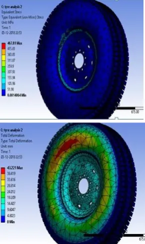
Tread 1 467.81
Tread 2 450.44
Table C :Comparision for vonmises stress on unloading condition
Figure 6: Comparison for vonmises stress on loading condition.
Treads Maximum Equivalent
Vonmises Stress (MPa)
Tread 1 498.19
Tread 2 465.86
Table D: Comparision for vonmises stress on loading condition
2.4Comparison for Total Deformation
2.4.1 Total Deformation on Loading Condition
Figure 7: Comparison for Total Deformation on loading condition
Treads Total Deformation
(mm)
Tread 1 76.678
Tread 2 63.244
Table E: Comparison for Total Deformation on loading condition
2.4.2 On unloading Condition
Figure 8: Comparison for Total Deformation on unloading condition
Treads Total Deformation (mm)
Tread 1 47.456
Tread 2 43.221
Figure F: Comparison of total deformation on unloading condition.
On comparing for total Deformation, unloading condition Tread 2 have lesser deformation value. On the other hand, for loading condition too Tread 2 have lesser deformation value. Hence Tread 2 is the best choice for the tread pattern.
This project focused on the tread pattern analysis. As one of the factor for heavy truck to maintain good grip over any type of surface is the Tread Pattern. With the two different tread patterns, we performed static structural analysis and came upon the following results.
Figure 1: Equivalemt Vonmises Stress on Unloading Conditions
Figure 1.1: Total Deformation on unloading Conditions
Figure 2.2: Total Deformation on loading Conditions
As we can observe in all the above comparison, we came to know that Tread 2 have the lowest Equivalent Vonmises Stress as well as Total Deformation. Hence, We consider Tread 2 as our best choice for tread pattern for best grip of our considered truck model TATA LPT 3118.
Table G: Material properties for final FE model of tyre
These comparison show that as simulation done by us have the comparable values with related to this research.
REFERANCE :
[1] https://en.wikipedia.org/wiki/Tire [2] https://en.wikipedia.org/wiki/Tread
[3] https://tatatrucks.tatamotors.com/tata-trucks/trucks/tata-lpt-3118/specifications.aspx
[4] https://www.researchgate.net/publication/296664322_Investiga tion_of_Shear_Stresses_in_the_Tire-Road_Contact_Patch [5] Compressive and Shear Analysis of Rubber Block Under Large
Strain : K. Sridharan and R. Sivaramakrishnan: DOI : 10.3844/ajassp.2013.681.687, American Journal of Applied Sciences ,Volume 10, Issue 7, Pages 681-687
[6] https://www.researchgate.net/publication/269222790_FEM_ba sed_parametric_design_study_of_tireprofile_using_dedicated_ CAD_model_and_translation_code
[7] https://www.researchgate.net/publication/313369980_Static_A nalysis_of_Truck_Wheel_Rim_using_ANSYS_Software [8]
http://iopscience.iop.org/article/10.1088/1757-899X/197/1/012042/pdf
[9] http://www.tiresciencetechnology.org/doi/abs/10.2346/1.21352 57
[10] http://www.tiresciencetechnology.org/doi/abs/10.2346/1.21487 93
[11] https://www.researchgate.net/publication/37846615_Nonlinear _finite_element_modeling_and_incremental_analysis_of_a_co mposite_truck_tire_structure
[12] K.B. Singh, M. Ali Arat, S. Taheri, An intelligent tire based tire–road friction estimation technique and adaptive wheel slip controller for antilock brake system, J. Dyn. Syst. Meas. Control 135 (2013) 031002,
doi:http://dx.doi.org/10.1115/1.4007704. Sidewall
Non-linear Ogden model
µ ɑ ɑ ɑ
Default values
5.037E+08 0.00286 5.528E+08 0.002959
Final values 5.037E+08 0.00286
5.528E+08 0.002959
Default 480 MPa 1 MPa 10 MPa 0 0 0.13
Percentage change
15.6 % 0 % 0 % 0 % 0 % 0 %
Final values 490 MPa 1 MPa 10 MPa 0 0
0.13 Tread
Neo-Hookean model
Default values
C10
Final values 1.803E+06
Linear Orthotropic
Ela Er Elo ɑ1 ɑ2 ɑ3
Default 460 MPa 10 MPa 350MPa
0.1 0.1 0.62
Percentage change
5 % 0 % 28 % 0 % 0 % 0 %