e-ISSN: 2250-3021, p-ISSN: 2278-8719
Vol. 3, Issue 9 (September. 2013), ||V1|| PP 01-09
Combined Economic And Emission Dispatch Using Artificial
Neural Network
Santhosh Kumar Kotagiri, Narendar Reddy Narra
Abstract: - This paper proposes an Artificial Neural Network approach for solving the Combined Economic and Emission Dispatch (CEED) problem using Radial Basis Function (RBF) based neural network. The purpose of CEED is to minimize both the operating fuel cost and emission level simultaneously while satisfying load demand and operational constraints. This multi-objective CEED problem is converted into a single objective function using a modified price penalty factor approach.
Index Terms: -economic dispatch, emission dispatch, price penalty factor, lambda iteration technique, radial basis function (RBF), clustering technique.
I. INTRODUCTION
The purpose of the traditional Economic Dispatch (ED) problem is to find the most economical schedule of the generating units while satisfying load demand and operational constraints. This involves allocation of active power between the units, as the operating cost is insensitive to the reactive loading of a generator, the manner in which the reactive load of the station is shared among various on line generator does not affect its economy[1].
The progress of optimal dispatch goes far back as the early 1920’s, when engineers were concerned with the problem of economic allocation of generation or the proper division of the load among the generating units available . Prior to 1930, various methods were in use such as: (a) the base load method where the next most efficient unit is loaded to its maximum capability, then the second most efficient unit is loaded, etc., (b). “best point loading,” where units are successively loaded to their lowest heat rate point, beginning with the most efficient unit and working down to the least efficient unit, etc. It was recognized as early as 1930, that the incremental method, later known as the “equal incremental method,” yielded the most economic results. In 1954, co-ordination equation was developed for solving economic dispatch problem. A break through in the mathematical formulation of the economic dispatch problem was achieved by Carpentier in the early 1960’s, who treated the entire work in an exact manner (active power and reactive power dispatch). The
Solution of Carpentier’s formulation is a non-linear optimization which has been the subject of much study though the present and its implementation in real time remains a challenge.
Several classical optimization techniques are used for solving economic dispatch problem. These are Lambda Iteration Method, Gradient method and Dynamic Programming (DP) method [1], etc. Among this lambda iteration method has been applied in extensively and used by power utilities due to its ease of implementation.
The conventional methods of economic dispatch are dealt with in detail by Allen J. Wood, Bruce F. Wollenberg [1], I. J. Nagrath, D.P. Kothari [2] and C. L. Wadhwa [3]. All these authors have presented algorithms for finding the solution to the economic generation scheduling by iterative methods based on exact co-ordination equation for determining the optimum plant allocations, and equal incremental cost principle for determining the allocation of different generators in a generating station.
M.R.Gentt and J.W.Lamont [4] have started the early work on minimum emission dispatch and proposed a method for on-line steam unit dispatch that results in the minimum NOX emissions. They had used
a combination of a straight line and an exponential term for the total NOX emissions. K. Srikrishna and
C.Palanichamy [5] have proposed a method for Combined Economic and Emission Dispatch (CEED) using price penalty factor. A modified price penalty factor is proposed in [6] to find economic emission fuel cost with respect to the load demand. In this the line flow constraints are computed directly from the Newton Raphson method.
Outlines of the paper
3.Radial Basis Function based Neural Networks including Clustering technique. 4 simulation results comparing with lambda method, discussions and conclusions.
II. COMBINED ECONOMIC AND EMISSION DISPATCH PROBLEM FORMULATION
The objective of Economic Dispatch (ED) is to minimize the total generation cost of a power system over some appropriate period:
1n i i i
Minimize F f P
(1)where, F : total generation cost (Rs/hr)
n : number of generators
Pi : real power generation of ith generator (MW)
fi (Pi) : generation cost for Pi Subject to a number of power systems network equality and inequality constraints. These constraints include:
2.1 System Active Power Balance
1
n
i D loss i
P P P
(2)where, PD : total system demand (MW) Ploss : transmission loss of the system (MW)
2.2 Generation Limits
,min ,max
i i i
P
P
P
(3)where, Pi,min : minimum power output limit of ithgenerator (MW)
Pi,max : maximum power output limit of ith generator (MW)
2.3 Combined Economic and Emission Dispatch
The economic dispatch and emission dispatch are considerably different. The economic dispatch deals with only minimizing the total fuel cost (operating cost) of the system violating the emission constraint. On the other hand emission dispatch deals with only minimizing the total emission of NOX from the system violating
the economic constraints. Therefore it is necessary to find out an operating point, that strikes a balance between cost and emission. This is achieved by combined economic and emission dispatch (CEED).
The multi-objective combined economic and emission dispatch problem is converted into single optimization problem by introducing price penalty factor h [12] as follows:
Minimize Φ = F + h* E (Rs./hr) (4)
subject to demand constraint (2) and generating capacity limits (3).
The price penalty factor h blends the emission with the normal fuel costs and Φ isthe total operating cost of the system (i.e., the cost of fuel + the implied cost of emission).
Once the value of price penalty factor is determined, the problem reduces to a simple economic dispatch problem. By proper scheduling of generating units, comparative reduction is achieved in both total fuel cost and NOx emission.
2.3. A Fuel Cost Objective
The classical economic dispatch problem of finding the optimal combination of power generation, which minimizes the total fuel cost while satisfying the total required demand, can be mathematically stated as follows
1
n
i i i
Minimize F f P
(5)where
fi(Pi) = aiPi2 + biPi + ci where, ai , biand ci are fuel cost coefficients.
2.3. B Emission Objective
The minimum emission dispatch optimizes emission objective, which can be modeled using second order polynomial functions
2
1
n
i i i i i i
Minimize E P P
(6)2.3. C Multi-objective Formulation
The multi-objective economic dispatch optimizes the above classical economic dispatch and emission dispatch
simultaneously which can be formulated as:
1
,
n
i i
Minimize
f F E
(7)where fi(F, E) = w1(aiPi2 + biPi + ci ) + w2hm(αiPi2 + βiPi + γi) here : hm is modified price penalty factor
: w1and w2 areweights (w1+ w2=1)
2.4 Procedure to Find Price Penalty Factor
The price penalty factor hi is the ratio between the maximum fuel cost and maximum emission of corresponding generator
,max,max
i i
i
F P h
E P
(Rs/Kg) , i = 1,2,…n. (8)
The price penalty factor for a particular load demand PD (MW) is computing as follows: 1) Find the ratio between maximum fuel cost and maximum emission of each generator. 2) Arrange the values of price penalty factor in ascending order.
3) Add the maximum capacity of each unit (Pi,max) one at a time, starting from the smallest hi unit until ∑Pi,max
≥ PD.
4) At this stage, hi associated with the last unit in the process is the price penalty factor for the given load.
2.5 Procedure to Find Modified Price Penalty Factor
The procedure just shown gives the approximate value of price penalty factor computation for the corresponding load demand. Hence, a modified price penalty factor hm is used in this project to give the exact value for the particular load demand. The first two steps of computation remain same for the calculation of modified price penalty factor. The remaining steps are modified as follows:
3) Form an array, m by adding Pi,max one by one from the lowest hi value unit.
4) Add the elements of mi one at a time, starting from the smallest hi unit until Σ m > PD
5) The modified price penalty factor hm is computed by interpolating the values of hi for last two units by satisfying the corresponding load demand.
III. RADIAL BASIS FUNCTION NETWORKS
To construct radial basis function (RBF) network previous data of CEED for different power demands with various weights are set by lambda iteration method.
Fig.1. Radial Basis Function Network Structure
ik s n s
k k
i c w
y .
1
x
for i=1,2…..m (9)where x = [x1, x2 ……… xn ] is an input vector, n is number of input vectors ck is the is the kth center node
center wik is the weight value between the kth center and the ith output layer. and m is the number of output
layers
h() is a strictly positive radially symmetric function with a unique maximum at its center j, and which drops off rapidly to zero away from the center. In other words, φkhas an appreciable value only when the “distance”
s
n
c
x
is smaller than the width . and φk is output of hidden layerand j , w j are center and width
Gaussian Function
3.1 Method for Selection of Centers:
Using K-Means Cluster Centers [7]: The objective is to locate a “set k of RBF centers that represent a local minimum of the SSE (sum of squared errors) between the training set vectors x and the nearest of the k
receptive field centersj.”
- In other words, the k RBF’s are initially assigned centers j, j=1, 2, …,k, which are set equal to k randomly
selected training vectors. The remaining vectors are assigned to class j of the closest center j. Next, the
centers are recomputed as the average of the training vectors in their class.
3.2 Method for Selection of Widths:
Distance Averaging [7]: A “Reasonable” estimate for the global width parameter is the Average j
i j
w , which represents a global average over all Euclidean distances between the center of
each unit i and that of its nearest neighbor j
3.3 Plan Of Training Data Created By Lambda Iteration Method
Inputs: power demand (Pd), operators preference (w1 and w2): all possible combinations of w1, and w2, both varying in steps of 0.05 in the range of 0 to 1
Output: Active power output of each generator 3.4 Parameter Setting
Input Nodes: 3 (Pd, w1, w2)
Hidden Nodes: 65(Selected by Clustering Technique) Output Nodes: No. of Generators
Learning rate(η): 0.0002 Acceleration Factor (α):0.995 Epsilon: 0.001
No of iterations: 1200 See Fig.2
3.5 Centers
Firstly no of centers required is chosen randomly about 1/5th to 1/7th of total number of patterns Those centers are chosen randomly among given patterns Such choosing must ensure that no two centers are very close to each other, or even next to each other but fairly far apart from each other covering the whole of input space.
Randomly chosen centers are finalized or adjusted according to clustering technique see fig.4, then weights b/w hidden layer and output layer are initialized randomly between 0 and 1. Then RBFNN is trained for iterations (some fraction of maximum iterations) or until convergence which is more than actually required (say 0.005/ 0.004 if actual is 0.001).Repeat above process for a few trials (say 5 to10 times) until satisfied results are obtained. After each complete trial/process store the finalized centers and weights onto a file and the most favorable set of centers and weights. After choosing, the most favorable centers and weights, they are taken as initial values for problem for the next time, instead of taking randomly the centers and weights see fig 3and fig.4. Above step can be repeated for faster convergence or quick weight stabilization processing
2
2 ) (
exp )
(
j j k
w x
x
IV. TEST RESULTS
The method, Combined Economic and Emission dispatch using RBF Network and lambda method was implemented on WSSC 9-Bus 3-Generator System, IEEE 30-Bus system that has 6-Generators [8] , Indian utility Practical System of Uttar Pradesh State Electricity Board (UPSEB) that is of 75-Bus 15-Generators [8].
Average Percentage Absolute Error (APAE) Considered has
Where m is No of generators
Test results:
The comparison of test results of RBF method and Lambda iteration method
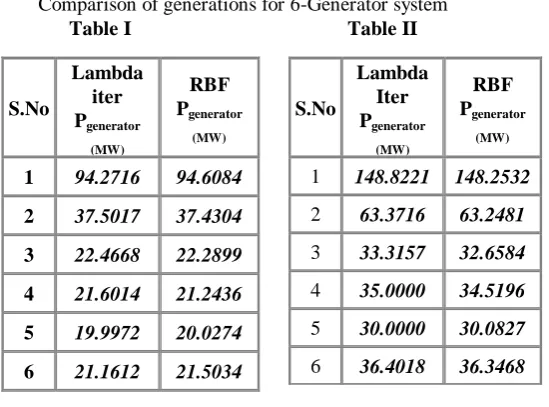
1. Table I Table II shows active power output of different unit in both methods for 6-Generator system ,same has Table III Table IV for 15-Generator system.
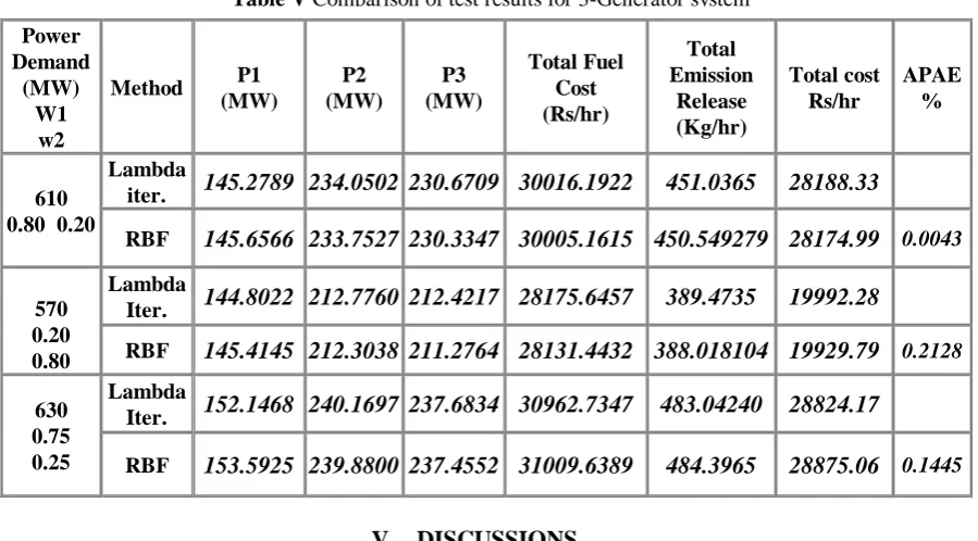
2. Case 1:In 3-Generator System
Table V shows active power output , APAE and cost of both methods with different demand and different weights
Case 2: IEE 30-Bus 6- Generator System Comparison of Total cost and APAE
In Table I (Pd=217, W1=0.3 , W2=0.7) the total cost of the lambda iteration method $/hr. 478 and RBF method $/hr. 479 APAE=0.084%.
In Table II (Pd=347, W1=0.5,W2=0.5) the total cost of the lambda method $/hr.997 and RBF method $/hr.989 APAE=0.633%.
Case 3:75-Bus 15-Generator System Comparison of Total cost and APAE
In Table III (Pd=3450, W1=0.7 , W2=0.3) the total cost of the lambda iteration method $/hr.5212 and RBF method $/hr.5227 , APAE=0.673% .
In Table IV (Pd=2750, W1=0.35,W2=0.65) the total cost of the lambda method $/hr.3861 and RBF method $/hr.3850 APAE=0.846%
Comparison of generations for 6-Generator system Table I Table II
S.No
Lambda Iter Pgenerator
(MW)
RBF Pgenerator
(MW)
1 148.8221 148.2532
2 63.3716 63.2481
3 33.3157 32.6584
4 35.0000 34.5196
5 30.0000 30.0827
6 36.4018 36.3468 S.No
Lambda iter Pgenerator
(MW)
RBF Pgenerator
(MW)
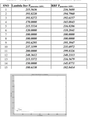
Table III Comparison of Generations for 15-Generator system
Table IV Comparison of Generations for15-Generator system
Fig.2. Error rate Vs Iter for RBF showing no of iterations (1200) for 0.005 Accuracy SNO Lambda Iter Pgenerator (MW) RBF Pgenerator (MW)
1 215.5636 216.5688
2 193.8220 194.7960
3 193.8272 192.6157
4 170.0000 165.0843
5 215.5534 216.8286
6 120.0000 118.2841
7 100.0000 100.0000
8 100.0000 100.0000
9 193.6295 195.3947
10 237.3199 235.6972
11 200.0000 199.8326
12 248.3612 248.2313
13 215.5572 216.5679
14 150.0000 145.8771
15 180.6130 182.8414
S.No Lambda Iter Pgenerator (MW) RBF Pgenerator (MW)
1 331.1324 331.1961
2 297.7298 290.7176
3 200.0000 201.1689
4 170.0000 171.0384
5 240.0000 241.4921
6 120.0000 121.5157
7 100.0000 100.2106
8 100.0000 99.8010
9 297.4392 297.4031
10 250.0000 252.1001
11 200.0000 198.9616
12 381.5344 381.9169
13 331.1302 331.1220
14 150.0000 152.2316
Fig.4. Flow chart of clustering technique 0: Initial RBF centers, *: Retained RBF centers
V. DISCUSSIONS
The results obtained from the three test cases the following observations are
1. As shown in Fig.3. the clustering technique can effectively reduce the size of the RBF network that provides some contributions in decreasing the computation time
2. Tables I III reveals that the present method has better estimating accuracy but total cost is little bit higher than actual value ,Tables II IV reveals that the present method has poor estimating accuracy but total cost is lesser than actual value
3. The performance of the present method is related to the estimating accuracy of the active power of each generation .since the estimating value of the each generator maybe higher or lower than the actual value. the solution with lower APAE seems not to ensure that it’s objective value including fuel cost, emission are closer to the actual objective value than other once with higher APAE value
VI. CONCLUSION
An algorithm has been developed for the determination of the global or near-global optimal solution for the Combined Economic and Emission Dispatch (CEED). The formulated algorithm of RBFNN has been tested for three test systems with three, six generating units and fifteen generating units. The results obtained from RBFNN method are compared with conventional lambda iteration method considering Average Percentage Absolute Error. The results obtained for three test systems are found to be in good agreement with conventional generation values from lambda technique. The RBFNN approaches provide a global optimal solution than the other methods
REFERENCES
[1] Allen J. Wood, Bruce F. Wollenberg, “Power Generation, Operation, And Control”, John Wiley & Sona, Inc., New York, 2004
[2] I. J. Nagrath, D.P. Kothari, “Modern Power System Analysis”, Tata McGraw-Hill Publishing Company Ltd., New Delhi, India, 1989.
[3] C. L. Wadhwa, “Electrical Power Systems”, New Age International (P) Ltd. Publishers, New Delhi, India, 2001.
[4] M R Gent, J W Lamont, “Minimum Emission Dispatch”, IEEE Trans. Power Apparat. Syst., Vol. 90, pp. 2650-2660, June 1971.
[5] Palanichamy.C, Srikrishna K. Economic thermal power dispatch with emission constraint, Journal of Institution of Engineers (India),Vol.72, pp.11-18, April 1991.
[6] P. Venkatesh, R. Gnanadass, and Narayana Prasad Padhy,“Comparison and application of evolutionary Programming techniques to combined economic Emission dispatch with line flow constraints”, IEEE Trans. Power Syst.,Vol.18, No. 2, pp 688-697, May 2003.
Power Demand
(MW) W1
w2
Method P1
(MW)
P2 (MW)
P3 (MW)
Total Fuel Cost (Rs/hr)
Total Emission
Release (Kg/hr)
Total cost Rs/hr
APAE %
610 0.80 0.20
Lambda
iter. 145.2789 234.0502 230.6709 30016.1922 451.0365 28188.33
RBF 145.6566 233.7527 230.3347 30005.1615 450.549279 28174.99 0.0043
570 0.20 0.80
Lambda
Iter. 144.8022 212.7760 212.4217 28175.6457 389.4735 19992.28
RBF 145.4145 212.3038 211.2764 28131.4432 388.018104 19929.79 0.2128
630 0.75 0.25
Lambda
Iter. 152.1468 240.1697 237.6834 30962.7347 483.04240 28824.17
[7] Christian J. Darken and John Moody by “Fast learning in networks of locally-tuned processing units, Nueral computation”Vol.1,No.2,pp 281-294,Summer1989.
[8] I. Jacob Raglend and Narayana Prasad Padhy “Solutions to Practical Unit Commitment Problems with Operational, Power Flow and Environmental Constraints” 2006 IEEE.
[9] E. H. Chowdhury, Saifur Rahrnan, “A Review of Recent Advances in Economic Dispatch”, IEEE Trans. on Power Syst., Vol. 5, No. 4, pp 1248- 1259, November 1990.
[10] A. A. El-Keib, H. Ma, J. L. Hart, “Economic Dispatch in View of The Clean Air Act of 1990”, IEEE Trans. Power Syst., Vol.9, No.2, pp. 972-978, May 1994.
[11] M. A. Abido, “Environmental/Economic Power Dispatch Using Multiobjective Evolutionary
Algorithms”, IEEE Trans. Power Syst., Vol.18, No. 4, pp 1529-1537, Nov. 2003.
[12] J. H. Talaq, F. El-Hawary, and M. E. El-Hawary, “A Summary of Environmental/Economic Dispatch algorithms,” IEEE Trans. Power Syst., vol. 9, No.3 , pp. 1508–1516, Aug. 1994.
[13] Chao-Ming Huang and Fu-Lu Wang “An RBF Network With OLS and EPSO Algorithms for Real-Time Power Dispatch”, IEEE Transactions On Power Systems, Vol. 22, No. 1, FEB 2007
Santhosh Kumar Kotagiri : II-M.tech at Sri Venkateshwara Engineering College ,Suryapet his interested in Power Electronics and Artificial Intelligent Systems