EFFECT OF INJECTOR ORIENTATION
ON VELOCITY VECTOR
COMPONENTS IN A DI DIESEL
ENGINE: ANALYSIS THROUGH CFD
SIMULATION
.
P.MANOJ KUMAR1. Prof .V.PANDURANGADU2
V.V.PRATIBHA BHARATHI3 V.V.NAGA DEEPTHI 4
1
Department of Mechanical Engineering, Stanley Stephen College of Engineering &Technology, Kurnool, A.P India
2&4
Department of Mechanical Engineering, JNT University, Anantapur, A.P., India 3
Department of Mechanical Engineering, SKD, Gooty, A.P., India
ABSTRACT
In direct injection (DI) diesel engines the effect of injector Orientation on velocity vector Components have high influence on engine performance as well as exhaust gas emissions. The fuel injector orientation plays very important role in fuel air mixing. A single cylinder four stroke DI diesel engine with fuel injector having multi-hole nozzle injector is considered for the analysis and a computational fluid dynamics (CFD) code, STAR-CD is used for the simulation. In the present study, various injector orientations are considered for the analysis. It is shown that there is an optimal injector orientation for the fuel in-cylinder fluid flow through velocity vectors at 950, 1000 and 1100 are discussed.
Key words: Diesel engine , spray, velocity vectors,
INTRODUCTION
To illustrate the potential for multidimensional modeling of internal combustion engine fluid flow and flow field, the results of which are presented in terms of velocity vector components[1].
Plots – Velocity vector components are indicated by the arrows for their direction and its size is indicated by the magnitude of the components[2].
It is logical to present the details in 2-D planes for better understanding, through the 3-D flow field. Velocity vectors are generated using CFD Code[5,6].
The flow in X-direction is called U-velocity components, in Y-direction is called V-velocity component and Z-direction in called W-velocity component. Large amounts of information on the fluid flow through velocity vectors are generated. It is difficult to present entire information, hence at selected crank angles which are felt necessary are only discussed in their respective section[3,4].
In this section the fluid flow field during part of compression and expansion strokes for three injector orientation of 950, 1000 and 1100 are discussed and analyzed on the basis of the fluid flow calculation plots in X-Z plan[9].
METHODOLOGY
Engine Geometry and Specifications
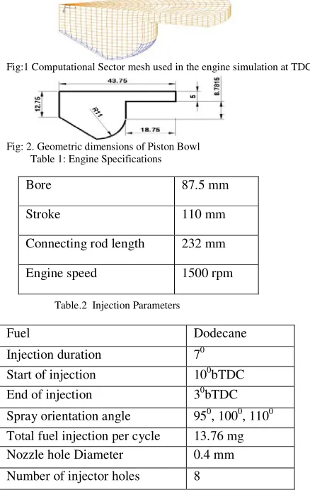
In the present work, 450 sector is taken for the analysis due to the symmetry of eight-hole injector in the model. The computational mesh when the piston is at Top Dead Center (TDC) is shown in figurre.1. The computational domain comprises of the combustion chamber with piston crown. The number of cells in the computational domain at TDC is 10608. Piston bowl dimensions are given in figure.2. Engine details are given in table.1 and fuel and injection details are given in table.2.
Fig:1 Computational Sector mesh used in the engine simulation at TDC
Fig: 2. Geometric dimensions of Piston Bowl Table 1: Engine Specifications
Table.2 Injection Parameters
Fuel Dodecane
Injection duration 70 Start of injection 100bTDC End of injection 30bTDC Spray orientation angle 950, 1000, 1100 Total fuel injection per cycle 13.76 mg Nozzle hole Diameter 0.4 mm Number of injector holes 8
Initial and Boundary Conditions
It is important to study the in-cylinder fluid dynamics during the later part of combustion and initial part of expansion strokes in DI diesel engines. Analysis is carried out from 400 before TDC (bTDC) to 800 after TDC (aTDC), as fuel injection combustion and pollutant formations are taken place during this period.
The initial swirl is taken as 2m/s and the constant absolute pressure and temperatures as 9.87 bar, 583 K respectively. The turbulent model has the Intensity-Length scale as 0.1 and 0.001 respectively and it shows no traces of fuel and exhaust gases. The initial surface temperatures of combustion dome region and piston crown regions are taken as 450 K and the cylinder wall region has temperature of 400 K.
RESULTS AND DISCUSSIONS
COMPARISON OF FLOW FIELDS AT 100 BEFORE TDC .
During compression stroke at 100 before TDC (fig:3), it is noticed the velocity vectors are oriented
Bore 87.5 mm
Stroke 110 mm
components are noticed at the bowl lip. At this stage the max velocities of 11m/s are noticed at the top of the bowl lip towards the cylinder head. A clear vertex formation at the lip of the bowl is noticed, this is mainly due to the interaction of substantial fluid flows from the squish region with the upward flow along the piston bowl walls. It is also noticed that the traces of fuel spray began at the axis of the bowl and along the walls of the bowl there is a higher velocity vectors oriented towards the upper side, this is due to the compression of in-cylinder fluids in the compression stroke.
Fig: 3 A Slice Showing Velocity Components of U-W in X-Z plane at 100
bTDC.
COMPARISON OF FLOW FIELDS AT 40 BEFORE TDC.
A little after fuel injection starts at 40 before TDC (fig: 4) the velocity vectors are noticed to be oriented in the direction of the fuel jet. This velocity vector plots give the clear visibility and more information on the spray oriented and on spreading into the cylinder.
It is noticed that the velocity in the range of 54 to 126 m/s are in the core of fuel jet. This is due to high velocity fuel spray through the injection nozzle. The high velocity fluid flows appear to push the in cylinder fluids in the direction of fuel spray due to the momentum exchange between fuel spray molecule and in cylinder fluid molecules.
At this stage the fuel jet is noticed to impinge on the surface of the cylinder walls in all the three cases. The high velocity fuel jet which is leaving from the nozzle spreads out as it entrains and mixes with in cylinder fluids. The outer surface of the fuel jet gradually break up into droplets of different size and miscible with the in cylinder fluids. As spray moves away from the nozzle, that spray diverges, its width increases and the velocity decrease. At this stage it is also noticed that the spray impinges with the chamber walls. The spray is then flows tangentially along the surface of the walls of the bowl. The cylinder wall causes the spray to split circumferentially in either direction one into the bowl region and other into the cylinder dome region.
In case of 950 orientation, it is noticed that the one weak vortex is noticed at the cylinder head near the bowl lip area. This is due to the strong flow from the fluid sprays are dominated the squish flows (flows from the squish region towards the bowl during compression), at this stage some of the fuel spray is noticed to spread towards the squish area this will be clearly observed with the fuel spray contour plots (fig xx). Another elongated vortex formation below the spray path is noticed .This is mainly due to the drag force created by the fuel jet.
In case of 1000 injector orientation, it is noticed that a vortex formation at lip of the bowl. It is also noticed that after hitting the spray particles on to the walls of the bowl surface. Some of the particles moving along the bowl surface towards the cylinder head and rest of the particles moving along the walls of the bowl towards down to the bowl region.
In case of 1100 orientation, it is noticed that an elongated vortex at the lip of the bowl downwards to the bowl region.
Fig: 4 A Slice showing Velocity Components of U-W in X-Z plane at 40
bTDC
COMPARISON OF FLOW FIELDS AT TDC.
At TDC (fig: 5), fluid flow velocities in the bowl region is noticed to be higher than that of the squish region. This is due to the stagnation of flows in the squish region, as well as due to narrow space between cylinder head and piston. It can also be observed that the traces of spray moving towards the bowl region.
In case of 950 orientation, two weak vertices one at the lip of bowl another one at side walls of the bowl are situated.
In case of 1000 orientation, two vortices on either side of spray path are noticed. It is also noticed that the vortices are rotating.
In case of 1100 orientation two elongated vortices one at the lip of the bowl towards the bowl region and at the bottom of the bowl are noticed.
Fig: 5 A Slice showing Velocity Components of U-W in X-Z plane at TDC.
COMPARISON OF FLOW FIELDS AT 20 AFTER TDC.
At 20 after TDC (fig: 6), at this stage it is during expansion stroke, the piston already has started moving towards bottom dead center.
In case of 950 orientation strong fluid flows moving from squish area towards the bowl through its expansion stroke, this can be attributed to the high pressure and temperature. A combustion fluid flow pushes the fluid particles toward the bowl region, where the required condition for combustion is provided at this area first. It is also noticed that the fluid flows near the cylinder head the combustion related flows completely reverted and move towards the axis of the cylinder.
In case of 1000 orientation can be observed that to move towards the squish region. In the bowl region
95 100
110
In case of 1100 orientation the flows started to move towards the squish region (reverse squish) due to space created during expansion stroke.
Fig: 6 A Slice Showing Velocity Components of U-W in X-Z plane at 20
aTDC.
COMPARISON OF FLOW FIELDS AT 80 AFTER TDC.
During expansion stroke at 80after TDC (fig: 7), it is noticed that the establishment of turbulent flows in the entire cylinder a clear strong vertices formation is observed in the bowl region.
In case of 950 orientation the flows from squish region flows towards the bowl is still continues and can be attributed that the combustion is continued in this region because of the injector orientation and also it is noticed that there is a fuel accumulation at this region .
In case of 1000 orientation some of the combustion related to flow moves in reverse squish direction towards the squish region, it indicates that the considerable quantity of combustion flames are moving in that direction.
In case of 110 orientation a small quantity of combustion flames are moving towards the squish region at the same time another weak elongated vortex formation is noticed at the axis of the bowl region, this is mainly attributed to the upward thrust due to the combustion taking place at the bottom side of the bowl region.
Fig: 7 A Slice Showing Velocity Components of U-W in X-Z plane at 80
aTDC .
COMPARISON OF FLOW FIELDS AT 220AFTER TDC
During expansion stroke at 220 after TDC (fig:8), a strong fluid flow wave is moving in reverse squish direction, this is mainly due to the space is being created during expansion stroke by the piston moving away from the cylinder head.
In case of 950 injector orientation, it is noticed that the flows from squish region towards the bowl region is still continuing. This is mainly due to combustion only, this is mainly due to injector orientation.
95
100 110
In case 1000 injector orientation it in noticed that the velocity vectors are more uniformly spread in the entire bowl. At this stage one strong vortex at the side walls of the bowl and a week elongated vortex at the axis of the bowl is noticed.
In case of 1100 injector orientation it is noticed that the one strong vertex at the side walls of the bowl and also another weak vortex formation at the axis of the bowl region.
Fig: 8 A Slice showing Velocity Components of U-W in X-Z plane at 220
aTDC .
CONCLUSIONS:
Effect of orientation on in-cylinder fluid flow characteristics through velocity vector components are performed in DI diesel engine through CFD simulation .Three injector orientations are considered for simulation. In case of 950 orientation there is a fuel spreading towards the squish region at the early stages of spray. There by more wetting area is noticed, and more combustion generated velocities and fluid flow from the squish region towards the piston bowl region .Though the piston moving away from the cylinder head in the expansion stroke .It is not desirable, in case of 1100 orientation there is a delay in fluid flows moving towards the squish region. In case of 1000 orientation there is a balance of spray spreading into the higher turbulent zone and more uniformly spreading of in-cylinder fluid flows are noticed. However 1000 orientation there is a reasonably good for the fuel spray.
REFERENCES:
[1] M. Auriemma, G. Caputo, F.E. Corcione, G. Valentino “ Influence of a Swirling Air flow on an evaporating Diesel spray from a
Common Rail injection Injection System under Realistic Engine Conditions. ” S.A.E. paper 2007-24-0021.
[2] K. Kajiyama, K. Nishida, A. Murakami, M. Arai, H. Hiroyasu An Analysis of Swirling Flow in Cylinder for Predicting D.I.Diesel
Engine Peformance .S.A.E. paper 84051.
[3] T. Bo, D. Clerides, A. D. Gosman and P. Theodossopoulos “Prediction of the Flow and Spray Processes in an Automobile DI Diesel
Engine” S.A.E. paper 970882.
[4] A.D. Gosmen “State of the art of multi-dimensional modeling of engine reacting flows” oil and gas science technology, Vol.54(1999).
[5] Paul Rodatz, German Weisser, and Franz X. Tanner “Assessment of CFD Methods for Large Diesel Engines Equipped with Common Rail Injection System” S.A.E. paper 2000-01-0948.
[6] Mehta P. S., Singal S. K. and Pundir B. P., “Fuel Spray-Air Motion Interaction in DI Diesel Engines: A Review” S.A.E. paper 930604.
[7] Timoney and Smith “Influences of Fuel Injection and Air Motion Energy Sources on Fuel-Air Mixing Rates in a D.I. Diesel Combustion System” S.A.E. Paper No: 960035.
[8] McCracken and Abraham “Swirl-Spray Interactions in a Diesel Engine” S.A.E. Paper No: 2001-01-0996.
[9] Lee, “Effect of Solid Body Rotating Swirl on Spray Tip Penetration” S.A.E. paper 970798.
ABOUT THE AUTHORS
1
Associate Professor in Mechanical Engineering Department, Stanley Stephen College of Engg. & Tech., Kurnool, Andhra Pradesh, India.
2
Professor of Mechanical Engineering Department, JNTU College of Engineering, Anantapur, Andhra Pradesh, India.
3
Assistant professor in Mechanical Engineering Department, SKD, Gooty, Andhra Pradesh ,India . 4
Assistant Professor of Mechanical Engineering Department, JNTU College of Engineering, Anantapur, Andhra Pradesh, India.