RESEARCH ARTICLE
Precise assembly of ring part
with optimized hollowed finger
Tomoya Fukukawa
1*, Junji Takahashi
2and Toshio Fukuda
3Abstract
We deal with a technical issue of assembling a ring part into a shaft part with the clearance of several micrometers by using a robotic manipulator. This issue is difficult because of deformation of a ring part compared with peg-in-hole assembly. We propose a precise assembly method of a ring part with finger shape to solve this issue. We also propose a method to decide design parameters of the finger by maximizing a closed area in Jamming diagram, which repre-sents a successful condition of assembling rigid parts by quasi-static force analysis. Finally, availability of the proposed method is verified by an experiment of ring assembly with a robotic hand attached to the designed fingers.
Keywords: Peg-in-hole, Ring assembly, Robotic manipulator
© 2016 Fukukawa et al. This article is distributed under the terms of the Creative Commons Attribution 4.0 International License (http://creativecommons.org/licenses/by/4.0/), which permits unrestricted use, distribution, and reproduction in any medium, provided you give appropriate credit to the original author(s) and the source, provide a link to the Creative Commons license, and indicate if changes were made.
Background
In recent years, many manufacturing companies have adopted Factory Automation (FA). Introduction of FA brings automation of various production processes, which are conducted by human workers, by machines, and can improve productivity, manufacturing cost, and quality of products. Although a paint process, a weld process and an inspection process have been automated increasingly, most of the assembly processes have been conducted manually by human workers even now. This is because assembly processes by a robot has many issues with regard to the precision and flexibility.
Assembly methods by a robot are divided into two categories by focusing on a process of mating: a passive assembly method and an active assembly method. The passive assembly method is a method that adjusts posi-tion and orientaposi-tion of a part automatically by using mechanical elastic elements or guiding jig. The passive assembly has advantage of high speed assembly because of sensor-less. However, the method is applied for only simple parts.
In contrast, the active assembly method is a method that controls impedance of an end effector properly with
sensor feedback. The method has advantage of versatility and can be applied for difficult assembly such as assem-bly of complex shape parts or flexible parts. However, the assembly time of the method tends to be larger than the passive assembly method.
Passive assembly methods have been studied since the 1980s. As a representative research of a passive assem-bly method, Whitney proposed Jamming diagram, which represents a successful condition in peg-in-hole task [1]. As a concrete example of passive assembly method, Remote Center Compliance (RCC) device has been also developed. Moreover, many researches have been stud-ied, and have extended application range of RCC devices [2–4]. Mouri et al. dealt with narrow clearance assembly and solved problems of high friction and jamming by adding high-frequency vibration to a peg during inser-tion process [5]. These conventional approaches have dis-advantages: A mechanical element, such as a spring and a rubber, need frequent maintenance due to their degrada-tion; the system tends to become large; the cost of design and production tends to become large.
Active assembly methods have been proposed much in recent years. Many researches of force sensor feedback [6, 7] or vision sensor feedback have been studied. Today, there are strong demand for assembly for flexible parts such as a cable and rubber. For example, Nakagaki et al.
Open Access
*Correspondence: [email protected]
1 Department of Mechanical Science and Engineering, Nagoya University, Furo-cho, Chikusa-ku, Nagoya 464-8603, Japan
tackled automatic insertions of linear and tubular flex-ible parts based on shape detection by vision sensor [8]. Even though many active assembly methods have been proposed, the methods that are used actually are few. One reason of this is difficulty of developing the system. Another reason is adaptability. Although human workers can detect and recover an error state of assembly quickly and succeed in the assembly smoothly, many assembly automation system cannot perform as well as human work.
In this paper, we focus on a precise ring assembly task as an example of difficult assembly. In the case of precise assembly that a clearance between a ring part and a shaft part is several micro meters, the assembly by a robotic manipulator is difficult. This is because a ring part deforms if the ring part is grasped by a robotic hand, and the clearance disappears. When practicability is consid-ered, it is desired that such difficult assembly is realized at high speed with minimal sensor system.
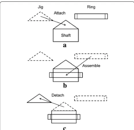
So far, the precise ring assembly task has been hann-dled by a method using a jig which is one of passive methods. The assembly processes are described in Fig. 1. In this conventional method, the precise ring assembly becomes easy by guiding a ring part along an incline of a jig (Fig. 1b). However, the method requires two pro-cesses of attaching a jig to a shaft part and detaching a jig from a shaft part as shown in Fig. 1a, c. Because the
two processes make cycle time long, the processes should be omitted. Originally, the function of the jig is to adjust the position and orientation of the ring by guiding along with the incline when the robotic hand pushes the ring straight down. In order to realize this guiding effect with-out using any jigs, we figured with-out a approach using a hol-lowed finger with an incline. Our proposed holhol-lowed finger also solves the problem of ring deformation due to hand grasping.
The finger design approach for realizing the handling an object including assembly have been studied long time. Most pioneering research of gripper design was done by Mason [9]. He formulated a planar pose prob-lem and found a pushing plan to move a polygonal object to a specified goal position and orientation. This concept has become underlying of the self-alignment mechanism on sensor-less gripper. Causey and Quinn summarized gripper design guidelines [10] and mentioned the impor-tance of grasped part alignment as well as the imporimpor-tance of part deformation avoidance for increasing reliabil-ity. Zhang and Goldberg proposed unique parallel-jaw grippers that can align an n-sided polygonal part in the vertical plane as the jaw close [11]. They also proposed a numerical algorithm to design optimal gripper jaws [12]. Hirata et al. proposed design of handling device for caging and aligning small circular objects [13]. By designing the triangular finger tips, their hand can grasp a small object robustly at a unique position of the tips. Although these conventional studies solve the problem of self-alignment of a part with gripper, the problem of alignment with other part is not considered. On the other hand, our proposed hollowed finger can align centers of a part and another part. The capability of self-alignment between two parts by using the hollowed finger is our original.
Methods
Successful condition of ring assembly
Geometrical condition
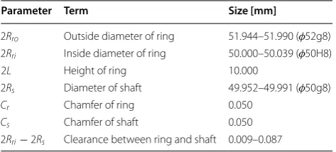
Figure 2 and Table 1 show parameters and sizes of a ring part and a shaft part dealt with in this research. As shown in Table 1, diameters of a ring part and a shaft part have size tolerance based on the Japanese Industrial Standards (JIS).
Ring assembly has two states: mating and inserting. Mating is a state that is most difficult in ring assembly. A definition of the state is that length of insertion is less than height of a ring. In the state, jamming, which is a situation that assembly is fixed because a state of a ring part and a shaft part is not desirable, occurs easily. Insert-ing is the next state after matInsert-ing. A definition of the state is that length of insertion is longer than height of a ring. Fig. 1 Conventional approach for ring assembly. a The robotic hand
We consider a geometrical successful condition of ring assembly. An angle between axes of a ring part and a shaft part should be small for proper mating. Let θm be a
maximum angular error of proper mating, then the suc-cessful condition is described as Eq. (1).
Let Rs and Rri be radiuses of a shaft and an inside radius of a ring.
Mechanical condition
We consider a mechanical successful condition of ring assembly. Jamming diagram is useful for considering a mechanical successful condition of mating [1]. Jam-ming diagram describes the successful condition on two-dimensional plane. Although conventional Jamming diagram is considered for the case of assembling a peg (shaft part) into a hole (ring part), we convert the pre-vious case into the case of assembling a ring part into a shaft part in this paper. Mechanical parameters for Jam-ming diagram is shown in Fig. 3. The parameters sum-marize in Table 2. By approximating θ ≈0 and assuming that the radial thickness of the ring is zero, three equa-tions are given as follows,
(1)
θ ≤θm=cos−1
Rs
Rri
By eliminating f1 and f2 from Eqs. (2), (3) and (4), Eq. (5) is given,
In the case that the angle of a ring is negative, Eq. (7) is given,
Additionally, a condition of friction is given as follows,
According to Eqs. (5), (7) and (8), Jamming diagram for ring assembly is obtained as shown in Fig. 4. If rela-tionship of mechanical parameters are in a closed area (hatching area in Fig. 4) of Jamming diagram, it is guaran-teed that ring assembly is realized smoothly.
(2) Fz−µf1−µf2=0
(3) Fx−f1+f2=0
(4) M−µf1Rri−f2l+µf2Rri=0
(5) M
RriFz
=µ(1−λ)Fx
Fz +λ
(6) λ= l
2µRri, 0≤l≤2L
(7) M
RriFz
=µ(1−λ)Fx
Fz
−λ
(8) −1
µ ≤ Fx
Fz
≤ 1 µ Fig. 2 Parameters of ring and shaft parts
Table 1 Parameters of ring and shaft parts Parameter Term Size [mm]
2Rro Outside diameter of ring 51.944–51.990 (φ52g8)
2Rri Inside diameter of ring 50.000–50.039 (φ50H8) 2L Height of ring 10.000
2Rs Diameter of shaft 49.952–49.991 (φ50g8) Cr Chamfer of ring 0.050
Cs Chamfer of shaft 0.050
2Rri−2Rs Clearance between ring and shaft 0.009–0.087
Fig. 3 Mechanical parameters of ring assembly
Table 2 Definition of mechanical parameters of ring assem-bly
Variable Definition
Fx Force in horizontal direction of ring Fz Force in vertical direction of ring M Moment applied to a ring f1, f2 Reaction force
µ Coefficient of friction between ring and shaft θ Angle of ring to shaft
Ring assembly with hollowed finger
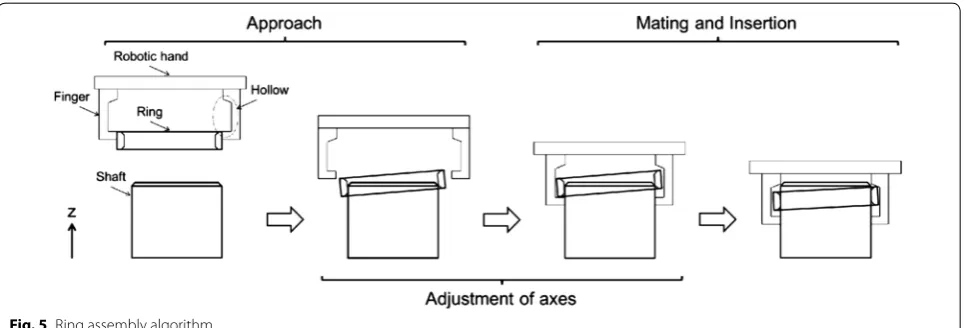
Based on the successful conditions of ring assembly, this section proposes a precise assembly method of a ring with hollowed finger. A characteristic of the proposed method is to assemble a ring part into a shaft part with a hollow of each finger of a robotic hand. The proposed method consists of three phases: approach, adjust-ment of axes, and mating and insertion. Figure 5 shows an overview of the proposed method. In the first phase, the manipulator with having a ring part approaches a shaft part and release and hang on the ring part to the shaft part. The disappearing of grip force restores cir-cular shape of the ring from deformation. In the second phase, the robotic hand goes down and holds a shaft part with covering the ring part in the hollows of fingers to adjust the axes of the robotic hand and the shaft part. In the third phase, the robot goes down and the ring part is assembled successfully by an effect of a space of the hollow. The proposed method has four advantages as follows.
• The proposed method does not have complicated
control
• The proposed method considers positional accuracy
of a robotic manipulator
• The proposed method considers size tolerance of
assembly parts (ring and shaft parts)
• The proposed method considers deformation of
assembly parts (ring part)
Approach
An objective of this step is rough positioning of a ring part to a shaft part. Firstly, the robotic manipulator picks up a ring part from a feeder. Then, the robotic manipula-tor approaches the shaft part and releases the ring part on the shaft part. In this case of precise assembly of a ring part, the assembly cannot succeed because a clear-ance between a ring part and a shaft part disappears by deformation of the ring part. Therefore, the ring part is released once. On the other hand, if the positional differ-ence between the ring part and the shaft part is large, the ring part falls from a shaft part. Therefore, it is assumed that the robotic manipulator is controlled with possible accuracy.
Adjustment of axes
One problem of assembly by a robotic manipulator is positional accuracy of the robot. In general, six-axis manipulators have positional error of more than 20 μM. Precise assembly cannot succeed with only position con-trol. An objective of this step is to reduce the positional and angular errors between the robotic hand and the shaft part.
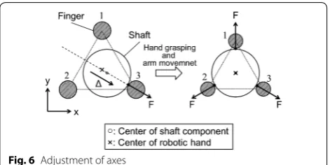
A hand grasping motion makes the fingers move toward the hand center with same width. When the hand center is not aligned with the shaft center, a finger contacts with the shaft in first even though others do not. The left figure in Fig. 6 shows that only the finger 3 Fig. 4 Jamming diagram for ring assembly
contacts with the shaft and the reaction force is gener-ated. The robotic arm moves the hand to the direction for reducing the reaction force simultaneously with the hand grasping motion. The arm motion is generated based on Eq. (9). The simultaneous hand grasping motion and the arm movement makes the centers of hand and shaft aligned.
where x,y are positional correction amount of the robotic hand, Fwrist
x ,Fywrist are force detected at the wrist of the robotic manipulator, K is a value of gain. At the same time of holding the shaft part, the ring part is trapped by the hollows of the fingers.
Mating and insertion
An objective of this step is to achieve mating and insert-ing the rinsert-ing part without jamminsert-ing. The robotic hand goes down in negative z direction along the shaft part. Posi-tional and angular errors between the ring part and the shaft part are reduced through the second phase. There-fore, the ring part is assembled successfully without com-plicated control.
Advantages of the hollows on fingers are as follows: prevention of ring deformation, geometrical restric-tion of a ring part, giving optimal mating force to a ring part. The first advantage is prevention of ring deforma-tion. A ring part held by a robotic hand is deformed by grip force. This means that a clearance between a ring part and a shaft part disappears. On the other hand, a ring closed by hollows of fingers does not receive grip force. Therefore, the proposed method can be applied to any material rings. The second advantage is geometrical restriction of a ring part. A position and an angle of a ring part are restricted by the hollows of fingers. The suc-cessful condition of ring assembly θ ≤θm in the previous
section is satisfied by the hollows of fingers. This means that a ring part can be assembled without jamming.
The final advantage is giving optimal mating force to a ring part. A ring part closed by hollows receives mating (9) x=K×Fxwrist
y=K×Fywrist
force from the top of the hollows. If the mating force satisfies Jamming diagram (Fig. 4), the ring part can be assembled without jamming.
Optimal design of finger shape
In this section, we determine parameters of the hollow. One of the characteristics of the proposed method is to assemble a ring part with hollows of fingers. The hollows need to be designed to be able to assemble a ring part successfully. The hollow has three parameters as follows: width a, height b, incline angle φ.
Geometric condition of ring assembly is shown as Eq. (1). Therefore, the hollow is designed as Eq. (1) is satis-fied. We consider a ring assembly with θ =θm (Fig. 7).
This is because the state is the most difficult state of ring assembly. In Fig. 7, let t be a cosine of ring thickness, h be difference between the highest point and the lowest point of a ring. Two parameters t and h are led to as follows.
By using Eq. (10), the parameters of width a and height b of hollows are determined.
Firstly, I determine a design condition of the width a of the hollow. Equation (1) is always satisfied when a≤t because of restriction in a horizontal direction. In addi-tion, the condition needs to satisfy (Rro−Rri)≤a not
to give external force in a radial direction of a ring part. From the above, the design condition of the width a of the hollow is as follows.
Next, I determine a design condition of the height b of the hollow. Likewise, Eq. (1) is always satisfied when
b≤h because of restriction in a vertical direction. In
addition, the condition needs to satisfy 2L≤b because of geometry. From the above, the design condition of the height b of the hollow is as follows.
(10) t=(Rro−Rri)cosθm+(2L−Cr)sinθm
(11)
h=2Rrosinθm+2Lcosθm
(12) (Rro−Rri)≤a≤t
(13) 2L≤b≤h
Fig. 6 Adjustment of axes
φ
θm
b
a
2Rro
h
t 2L
Cr
2L Fh
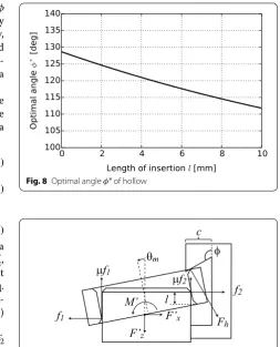
We determine a design condition of the incline angle φ
of the hollow. The principle is that area surrounded by Jamming diagram, which shows simplicity of assembly, is maximum. Therefore, the incline angle φ is introduced
into the equations of Jamming diagram. Then, we deter-mine the optimal incline angle φ∗ by maximizing the area of Jamming diagram.
Regarding ring assembly, equilibrium equations of force and moment considering mating force from the hollow are shown as follows. We assume that the radial thickness of a ring is zero.
where force from the hollow defines Fh, forces and a moment from the hand which are not involving Fh are Fx , ′ F′
y, and M′. The fourth term of Eq. (14) means a force part
in a vertical direction for mating. The fourth term of Eq. (15) means a force part in a horizontal direction for adjust-ing a position of a radjust-ing. The fifth and sixth terms of Eq. (16) means a moment part for adjusting an angle of a ring.
According to eliminating the contact force f1 and f2 from Eqs. (14), (15) and (16), Eq. (17) is led to.
A condition that the area of Jamming diagram is maxi-mum is that an intercept in Eq. (17) is maximum. The condition is shown as follows.
Therefore, the optimal incline angle φ∗ is led to as follows.
Equation (20) has a variable λ=l/2µRri, and depends on a length of insertion l. This means that the optimal incline angle φ∗ is not determined uniquely. A relation-ship between φ∗ and l is shown in Fig. 8. From Fig. 8, the optimal incline angle φ∗ is an obtuse angle.
We modify Figs. 7, 8, 9 so that the Eqs. (14)–(16) can be still applied even when the φ is obtuse angle. Here, we
define a new parameter c as the width of upper side of the hollow. The limitation of c comes from the condition that (14)
F′
z−µf1−µf2+Fhsinφ =0
(15) F′
x−f1+f2−Fhcosφ=0
(16)
M′−µf1Rri−f2l+µf2Rri
−Fhsinφ·(Rri+Cr)+Fhcosφ·2L=0
(17)
M′
RriFz′
=µ(1−λ)F ′ x
F′ z
+λ−cos(φ+ψ )Fh
F′ z
(18) ψ =tan−1
1+λ+Cr/Rri
µ(1−λ+2L/µRri)
(19)
cos(φ∗+ψ )= −1
(20)
φ∗
=π−ψ
=π−tan−1
1+λ+Cr/Rri µ(1−λ+2L/µRri)
the upper side of the hollow contacts with the ring at the inner edge. This limitation is expressed as follows,
In the case a<c, the insertion process needs to be modi-fied for avoiding a collision between the upper side of hollow and the shaft. The modification is that the hand opens little width when the insertion length l reaches 3/2L. This hand open motion has little effect on the sta-bility of the mating and insertion process, because it is done after the ring is almost inserted. Besides, this pro-cess takes virtually no time at all.
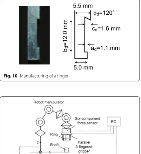
We determine an unique incline angle φd for
manu-facturing. A condition is that mating and insertion force is minimum in a process of assembly. The condition is described as Eq. (22).
From Eq. (22), the incline angle is designed as φd=120°. The other parameters of the lower width, the height, and upper width are determined by Eqs. (12), (13) and (21). Actual design conditions are described as follows.
(21) 2Lsin(θm)+a<c.
(22)
φd =arg min
2L
0
Fhsinφ∗dl
Fig. 8 Optimal angle φ∗ of hollow
φ θm
µf1
f1
µf2
f2 l
F’x F
h F’z
M’
c
One of the above conditions only have to be satisfied to give geometric restriction to a ring part. Therefore, the lower width, height and upper width are designated as
ad=1.1 (mm), bd=12.0 (mm), and cd=1.6 (mm). An
actual manufactured finger is shown in Fig. 10.
Results and discussion Experimental setup
Figure 11 shows an experimental system for ring assem-bly. A robotic manipulator is an articulated robot RV-1A (Mitsubishsi Electric Corp.). A robotic hand is a three-fingered gripper ESG1 (TAIYO, Ltd.). A force sensor is a six-part force sensor (NITTA Corp.).
Experiment
Figure 12 shows z-axis force: Fz from the force sensor
during mating process in the case of φ=61°: out of the design condition, 85°: within the design condition but not optimal, and 120°: optimal design. In the case φ=61°, the Fz increases rapidly when the insertion length: l reaches
5 mm. This is because the jamming is occurred and the (23)
1.00 mm≤a≤1.19 mm
(24)
10.00 mm≤b≤11.00 mm
(25)
1.24 mm≤c
mating process results in failure. On the other hand, in the case φ=85 and 120° the insertion length exceeds 10 mm, which is the height of the ring, and it can be con-firmed that the mating and insertion process succeeded.
Comparing with the case 85° and the case 120°, the Fz of the latter is lower than that of the former until l=8 mm. This results suggest that the optimal design of the φ has better performance in self-alignment than
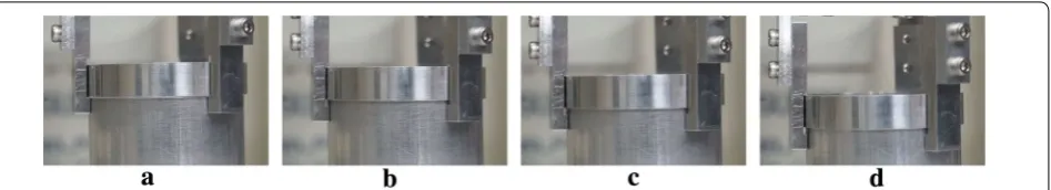
oth-ers. The reason why the Fz increases after l=8 mm in the case 120° is thought to be that the upper side of the hollow collides against the shaft. This collision can be avoided by opening the robotic hand more early timing. Figure 13 shows a sequence of ring assembly in the case of φ =120°.
We also conducted multiple assembly experiments to evaluate a success rate of the proposed method. The number of success was 19 out of 20 trials and the success ratio was 95 %. The failure in our experiments occurred in the first step of the proposed method. This means that the released ring fell from the shaft. Therefore, the effect of the proposed hollows is verified although the proposed method should be improved. To avoid the failure, the error recovery method should be developed in the future.
Conclusions
In this study, we proposed a precise assembly method of a ring part with hollowed fingers. Ring’s deforma-tion in a radial direcdeforma-tion is a problem in ring assembly. To solve the problem, the proposed method utilizes hol-lowed fingers. In the proposed method, a ring part caged in the space of hollows is assembled to a shaft part with-out deformation. In addition, the proposed method can achieve precise ring assembly without sensor feedback.
φd=120°
ad=1.1 mm
d
=12.0 mm
cd=1.6 mm
5.0 mm 5.5 mm
Fig. 10 Manufacturing of a finger
Fig. 11 Experimental system
0 1 2 3 4 5 6 7 8 9 10 11 12 13 14 15 16 0.0
2.0
1.0
0.2 0.4 0.6 0.8 1.2 1.4 1.6 1.8
Insertion length: l [mm]
Reaction force:
Fz
[N
]
φ= 61°
φ= 85°
φ=120° (a) (b)
(c) (d)
We also discussed optimization of the shape of hollows in this paper. The shape of hollows is optimized by geo-metrical and mechanical conditions of ring assembly. We verified that the proposed method can realize precise ring assembly by assembly experiments.
Authors’ contributions
TF formulated concepts and ideas and drafted this manuscript. JT and TF contributed concepts and edited and revised this manuscript. All authors read and approved the final manuscript.
Author details
1 Department of Mechanical Science and Engineering, Nagoya University, Furo-cho, Chikusa-ku, Nagoya 464-8603, Japan. 2 Department of Integrated Information Technology, Aoyama Gakuin University, 1-10-5, Fuchinobe, Chuo-ku, Sagamihara 252-5258, Japan. 3 Faculty of Science and Engineering, Meijo University, 1-501, Shiogamaguchi, Tenpaku-ku, Nagoya 468-8502, Japan.
Competing interests
The authors declare that they have no competing interests.
Received: 16 August 2015 Accepted: 11 June 2016
References
1. Whitney DE (1982) Quasi-static assembly of compliantly supported rigid parts. J Dyn Syst Meas Control 104:65–77
2. Sturges RH (1988) A three-dimensional assembly task quantification with application to machine dexterity. Int J Robot Res 7(4):34–78
3. Sathirakul K, Sturges RH (1998) Jamming conditions for multiple peg-in-hole assemblies. Robotica 16:329–345
4. Fei Y, Zhao X (2005) Jamming analyses for dual peg-in-hole insertions in three dimensions. Robotica 23:83–91
5. Mohri N, Saito N (1994) Some effects of ultrasonic vibration on the insert-ing operation. Int J Adv Manuf Technol 9(4):225–230
6. Qiao H, Dalay B, Parkin R (1993) Robotic peg-hole insertion operations using a six-part force sensor. J Mech Eng Sci 207(5):289–306 7. Kim IW, Lim DJ, Kim KI (1999) Active peg-in-hole of chamferless parts
using force/moment sensor. Proc IEEE/RSJ Int Conf Intell Robot Syst 2:948–953
8. Nakagaki H, Kitagaki K, Ogasawara T, Tsukune H (1996) Study of insertion task of a flexible wire into a hole by using visual tracking observed by stereo vision. Proc IEEE/RSJ Int Conf Robot Autom 4:3209–3214 9. Akella S, Mason MT (1998) Posing polygonal objects in the plane by
pushing. Int J Robot Res 17(1):70–88
10. Causey GC, Quinn RD (1998) Gripper design guidelines for modular manufacturing. Proc IEEE Int Conf Robot Autom 2:1453–1458 11. Zhang MT, Goldberg K (2002) Gripper point contacts for part alignment.
IEEE Transact Robot Autom 18(6):902–910
12. Zhang MT, Goldberg K (2006) Designing robot grippers: optimal edge contacts for part alignment. Robotica 25:341–349
13. Hirata Y, Kaisumi A, Yamaguchi K, Kosuge K (2011) Design of handling device for caging and aligning circular objects. Proc IEEE Int Conf Robot Autom 4370–4377