Electric Springs Comparison with Multilevel -Based STATCOM
Distributed Voltage Control
Bomma Shwetha
1,Bandi Sumalatha
32,Ralla Ramya
3 1M.Tech POWER ELECTRONICS JNTUH Hyderabad, Telangana, India.2M.Tech POWER ELECTRONICS in 2017 JNTUH, Hyderabad, Telangana, India. [email protected]
3 M.Tech POWER ELECTRONICS AND ELECTRIC DRIVES JNTUH, Telangana ,India. [email protected]
Abstract— The concept of electric spring (ES) has been proposed recently as an effective means of distributed voltage control. The idea is to regulate the voltage across the critical (C) loads while allowing the noncritical (NC) impedance-type loads (e.g., water heaters) to vary their power consumption and thus contribute to demand-side response. In this paper, a comparison is made between distributed voltage control using ES against the traditional single point control with STATic COMpensator (STATCOM). For a given range of supply voltage variation, the total reactive capacity required for each option to produce the desired voltage regulation at the point of connection is compared. A simple case study with a single ES and STATCOM is presented first to show that the ES and STATCOM require comparable reactive power to achieve similar
voltage regulation. Comparison between a
STATCOM and ES is further substantiated through similar case studies on the IEEE 13-bus test feeder system and also on a part of the distribution network in Sha Lo Wan Bay, Hong Kong. In both cases, it turns out that a group of ESs achieves better total voltage regulation than STATCOM with less overall reactive power capacity. Dependence of the ES capability on proportion of critical and NC load is also shown.
Index Terms—Demand response, electric springs (ES), STATic COMpensator (STATCOM), voltage control, voltage regulation.
I.
INTRODUCTIONVOLTAGE control in medium voltage (MV) or low voltage (LV) distribution networks is typically exercised through transformer tap-changers and/or switched capacitors/reactors. Sometimes a STATic COMpensator (STATCOM) is used for fast and precise voltage regulation, especially for the sensitive/critical loads [1].The novel concept of electric spring (ES) has been proposed as an effective means of distributed voltage control [2]. The idea is
improve power quality (PQ) in distribution systems. STATCOM is popularly accepted as a reliable reactive power controller replacing conventional var compensators, such as the thyristor-switched capacitor (TSC) and thyristor-controlled reactor (TCR). This device provides reactive power compensation, active power oscillation damping, flicker attenuation, voltage regulation, etc. Generally, in high-power applications, var compensation is achieved using multilevel inverters [2]. These inverters consist of a large number of dc sources which are usually realized by capacitors. Hence, the converters draw a small amount of active power to maintain dc voltage of capacitors and to compensate the losses in the converter. However, due to mismatch in conduction and switching losses of the switching devices, the capacitors voltages are unbalanced. Balancing these voltages is a major research challenge in multilevel inverters. Various control schemes using different topologies are reported. Among the three conventional multilevel inverter topologies, cascade H-bridge is the most popular for static var compensation [5], [6]. A multilevel converter not only achieves high power ratings, but also enables the use of renewable energy sources. Renewable energy sources such as photovoltaic, wind, and fuel cells can be easily interfaced to a multilevel converter system for a high power application [1-3]. The concept of multilevel converters has been introduced since 1975 [4]. The term multilevel began with the three-level converter [5]. Subsequently, several multilevel converter topologies have been developed [6-13]. However, the elementary concept of a multilevel converter to achieve higher power is to use a series of power semiconductor switches with several lower voltage dc sources to perform the power conversion by synthesizing a staircase voltage waveform. Capacitors, batteries, and renewable energy voltage sources can be used as the multiple dc voltage sources.A multilevel converter has several advantages over a conventional two-level converter that uses high switching frequency pulse width modulation (PWM). The attractive features of a multilevel converter can be briefly summarized as follows. ● Staircase waveform quality: Multilevel converters not only can generate the output voltages with very low distortion, but also can reduce the dv/dt stresses; therefore electromagnetic compatibility (EMC) problems can be reduced. ● Common-mode (CM) voltage: Multilevel converters produce smaller CM voltage; therefore, the stress in the bearings of a motor connected to a multilevel
motor drive can be reduced. Furthermore, CM voltage can be eliminated by using advanced modulation strategies such as that proposed in [14]. ● Input current: Multilevel converters can draw input current with low distortion. ● Switching frequency: Multilevel converters can operate at both fundamental switching frequency and high switching frequency PWM. It should be noted that lower switching frequency usually means lower switching loss and higher efficiency. Unfortunately, multilevel converters do have some disadvantages. One particular disadvantage is the greater number of power semiconductor switches needed. Although lower voltage rated switches can be utilized in a multilevel converter, each switch requires a related gate drive circuit. This may cause the overall system to be more expensive and complex.
Fig.1TypicalCircuitTopologiesof MultilevelInverters. ELECTRIC SPRING (ES) CONCEPT
Voltage control in LV and MV distribution networks and demand-side management (DSM) have traditionally been treated and tackled separately. Voltage control is usually achieved by control devices discussed in the previous section. DSM, on the other hand, is employed in a more distributed fashion (often at the appliance level) and is predicated on intelligence or communication facility in the appliance [10]–[12]
Fig. 2. Simulation set-up with an intermittent source and an equivalent power grid.
Alternatively, an integrated approach to voltage control and aggregated demand action could be achieved by separating the loads into critical (C) loads requiring constant voltage and uninterrupted supply and NC, impedance-type loads. At times of generation shortfall or network constraint, the voltage of the NC loads is reduced while regulating the voltages across the C loads. This addresses the generation shortfall or network constraint and also facilitates better voltage regulation of the C loads through manipulation of the supply impedance voltage drop. One way to exercise this control is to use the so-called ESs which are power electronic compensators that inject a voltage with controllable magnitude VES in series with each NC load to regulate the voltage VC across the C load as shown in Fig. 1. The voltage VNC across the NC loads is thus controlled (within allowable bounds) and the active power consumed by them modulated. The series combination of the ES and the NC load thusactsasasmartloadwhichensurestightlyregulatedvol tage across the C load while allowing its own power consumption to vary and thereby, participate in demand-side response. Adding the voltage VES in quadrature with the current flowing through the ES ensures exchange of reactive power only like conventional voltage compensators including STATCOM. For further details about ESs the readers can refer to [2] and [5].
III. ES VERSUS STATCOM
Test System In order to compare the voltage regulation performance of a single ES against that of a STATCOM, a simple test system as shown in Fig. 2 has been considered. It comprises of a power source acting as the main power grid and a separate controllable power source to emulate an intermittent renewable
(a)
(b)
( C)
(d)
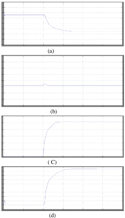
Fig. 3. System response following decrease in reactive power consumption of the intermittent source from 467 to 110 VAr. (a) Non-critical load voltage.(b)Criticalloadvoltage.(c)Electricspringvoltag e.(d)Reactivepowerexchange.
representing the ES is controlled using a PI controller to minimize the difference between the actual and reference values of the voltage across the C load. Phase angle of the voltage source is locked in quadrature to the phase angle of series current to ensure there is no active power transfer. The STATCOM is modeled by a controllable voltage source in series with impedance. Its control circuit is very similar to that of ES except for the adjustments due to its parallel connection to the C and NC load. B. Voltage Suppress Mode The voltage across the loads is increased above the nominal value (216 V) by reducing the reactive power absorption of the renewable source. This is to test the ability of an ES and a STATCOM to suppress the voltage and regulate it at the nominal value. At t = 1.0 s, the reactive power absorption by the intermittent renewable source is reduced from 467 VAr down to 110 VAr. Without any voltage control, the load voltage increases from the nominal value of 216 V up to 224 V as shown by Fig.3(a) and (b). Both STATCOM and ES are able to restore the voltage across the C load back to the nominal value as shown by the overlapping blue and red traces in Fig. 3(b). The ES achieves this by injecting about 115 V in series with the NC load the voltage across which drops to about 185 V as shown by the blue traces in Fig. 3(a) and (c). In order to suppress the voltage, both ES and STATCOM absorb reactive
(a)
(b)
(c)
(d)
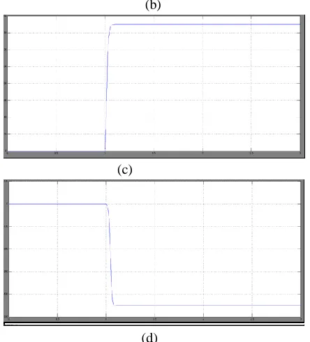
Fig. 4. System response following increase in reactive power consumption of the intermittent source from 467 to 1100 VAr. (a) Noncritical load voltage.(b)Criticalloadvoltage.(c)Electricspringvoltag e.(d)Reactivepowerexchange.
power (as indicated by positive sign of Q) from the system as shown in Fig. 3(d) with ES requiring to absorb about 100 VAr more than the STATCOM. It is observed that the reactive power consumed by ES to restore the C load voltage to normal value is higher than the reactive power consumed by STATCOM to achieve the same voltage. This can be explained from Fig. 1. An increase in ES voltage will result in a decrease in NC load voltage. This causes a decrease in the active power consumption of the (resistive) NC load. In order to have a higher overall active/reactive power consumption for the smart load, ES has to consume more reactive power. Note that the X/R ratio is not large (about 2) in this case which is why both active and reactive power affect the voltage regulation.
it at the nominal value. At t = 1.0 s, the reactive power absorption by the intermittent renewable source is increased from 467 to 1100 VAr. Without any voltage control, the load voltage is seen to drop from the nominal value of 216 V to slightly below 190 V as shown by the green trace in Fig. 4(a) and (b). As before, both STATCOM and ES are able to restore the voltage across the C load back to the nominal value as shown by the overlapping blue and red traces in Fig. 4(b). The ES achieves this by injecting about 150 V in series with the NC load the voltage across which drops to about 150 V as shown by the blue traces in Fig. 4(a) and (c). In order to suppress the voltage, both ES and STATCOM inject reactive power (as indicated by negative sign of Q) into the system as shown in Fig. 4(d) with ES requiring to inject about 150 VAr less
Fig. 5. System response for different distribution of noncritical and critical loads (NC:C). Disturbance is increase in reactive power consumption of the intermittentsourcefrom467to1100VAr.(a)Noncriticall oadvoltage.(b)Critical load voltage. (c) Electric spring voltage. (d) Reactive power exchange.
than the STATCOM. This is due to the fact that an increase in ES voltage will result in a reduction of NC load voltage which causes a decrease in active power consumption of the (resistive) NC load. Hence, the ES needs to produce less reactive power than an equivalent STATCOM to restore the system voltage due to the similar arguments about the X/R ratio as mentioned earlier for the voltage suppress case.
V. SIMULATION RESULTS WITH ES
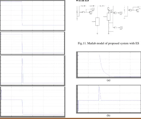
Fig.11. Matlab model of proposed system with ES
(a)
(c)
(d)
Fig. 13. System response following decrease in reactive power consumption of the intermittent source from 467 to 110 VAr. (a) Non-critical load voltage. (b) Critical load voltage. (c) Electric spring
voltage. (d) Reactive power exchange.
(a)
(b)
(c)
(d)
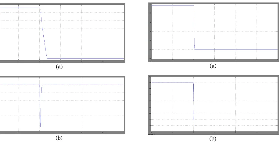
Fig. 14. System response following increase in reactive power consumption of the intermittent source from 467 to 1100 VAr. (a) Noncritical load voltage. (b) Critical load voltage. (c) Electric spring
voltage. (d) Reactive power exchange.
(a)
(c)
(d) (i) NCC= 1.9
(a)
(b)
(c)
(d) (ii) NCC=5.5
(a)
(b)
(d) (iii) NCC=9.1
Fig. 15. System response for different distribution of noncritical and critical loads (NC:C). Disturbance is
increase in reactive power consumption of the intermittent source from467 to 1100 VAr.(a) Noncritical load voltage.(b) Critical load voltage. (c) Electric spring voltage. (d) Reactive power exchange.
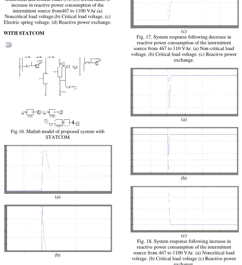
WITH STATCOM
Fig.16. Matlab model of proposed system with STATCOM
(a)
(b)
(c)
Fig. 17. System response following decrease in reactive power consumption of the intermittent source from 467 to 110 VAr. (a) Non-critical load voltage. (b) Critical load voltage. (c) Reactive power
exchange.
(a)
(b)
(c)
Fig. 18. System response following increase in reactive power consumption of the intermittent source from 467 to 1100 VAr. (a) Noncritical load voltage. (b) Critical load voltage (c) Reactive power
exchange.
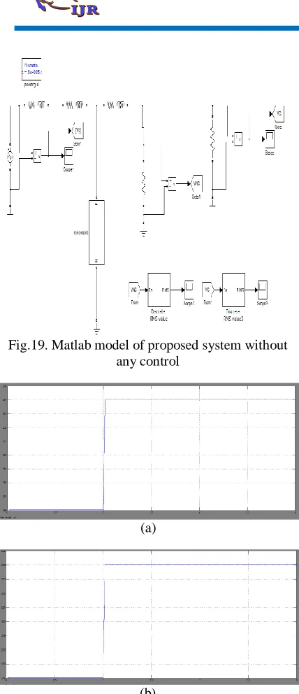
Fig.19. Matlab model of proposed system without any control
(a)
(b)
Fig. 20. System response following increase in reactive power consumption of the intermittent source from 467 to 1100 VAr. (a) Noncritical load
voltage. (b) Critical load voltage
(a)
(b)
Fig. 21. System response for different distribution of noncritical and critical loads (NC:C). Disturbance is increase in reactive power consumption of the intermittent source from467 to 1100 VAr.(a) Noncritical load voltage.(b) Critical load voltage.
VII. CONCLUSION
In this paper, a comparison is made between distributed voltage control using ES against the traditional single point control with STATCOM. For a given range of supply voltage variation, the total voltage regulation, and the total reactive capacity required for each option to produce the desired voltage regulation at the point of connection are compared. A simple case
REFERENCES:
[1] N. G. Hingorani and L. Gyugyi, Understanding FACTS: Concepts and Technology of Flexible AC Transmission Systems. Piscataway, NJ, USA: IEEE Press, 2000.
[2] S. Y. Hui, C. K. Lee, and F. F. Wu, “Electric springs: A new smart grid technology,” IEEE Trans. Smart Grid, vol. 3, no. 3, pp. 1552–1561, Sep. 2012. [3] A. Brooks, E. Lu, D. Reicher, C. Spirakis, and B. Weihl, “Demand dispatch,” IEEE Power Energy Mag., vol. 8, no. 3, pp. 20–29, May/Jun. 2010. [4] D. Westermann and A. John, “Demand matching wind power generation with wide-area measurement and demand-side management,” IEEE Trans. Energy Convers., vol. 22, no. 1, pp. 145–149, Mar. 2007.
[5] C. K. Lee and S. Y. Hui, “Reduction of energy storage requirements in future smart grid using electric springs,” IEEE Trans. Smart Grid, vol. 4, no. 3, pp. 1–7, Sep. 2013.
Emerg. Sel. Topics Power Electron., vol. 1, no. 1, pp. 18–27, Mar. 2013.
[7] C. K. Lee, N. R. Chaudhuri, B. Chaudhuri, and S. Y. R. Hui, “Droop control of distributed electric springs for stabilizing future power grid,” IEEE Trans. Smart Grid, vol. 4, no. 3, pp. 1558–1566, Sep. 2013.
[8] J. Dixon, L. Moran, J. Rodriguez, and R. Domke, “Reactive power compensation technologies: State-of-the-art review,” Proc. IEEE, vol. 93, no. 12, pp. 2144–2164, Dec. 2005.
[9] T. J. E. Miller, Reactive Power Control in Electric Systems. Hoboken, NJ, USA: Wiley, 1982. [10] P. Palensky and D. Dietrich, “Demand side management: Demand response, intelligent energy systems, and smart loads,” IEEE Trans. Ind. Informat., vol. 7, no. 3, pp. 381–388, Aug. 2011. [11] M. Parvania and M. Fotuhi-Firuzabad, “Demand response scheduling by stochastic SCUC,” IEEE Trans. Smart Grid, vol. 1, no. 1, pp. 89–98, Jun. 2010.
[12] M. Pedrasa, T. D. Spooner, and I. F. MacGill, “Scheduling of demand side resources using binary particle swarm optimization,” IEEE Trans. Power.
BOMMA SHWETHA
Completed B.Tech in Electrical & Electronics Engineering in 2014 under JNTU UNIVERSITY,HYDERABAD and M.Tech(POWER ELECTRONICS) in 2016 under JNTUH, Hyderabad, Telangana, India. I am working as an assistant professor. Area of interest includes power electronics.
E-mail id;[email protected]
BANDI SUMALATHA Completed B.Tech in Electrical & Electronics Engineering in 2013 under JNTU UNIVERSITY, HYDERABAD andM.TechPOWERELECTRONICS in 2017 under JNTUH,Hyderabad,Telangana,India. Email id: [email protected]
RALLA RAMYA