A 3-Phase Nine Level Inverter for PV cell
fed Induction Motor Drive
Mr. Medineni Prasanna Chowdary
M-tech Student Scholar Department of Electrical & Electronics Engineering, Sri Indu Institute of
Engineering & Technology; Hyderabad, Telangana, India.
Mrs. R.MANASA
Assistant Professor Department of Electrical & Electronics Engineering, Sri Indu Institute of
Engineering & Technology; Hyderabad, Telangana, India.
Mr. Suresh H Ballala
HOD Department of Electrical & Electronics Engineering, Sri Indu Institute of Engineering &
Technology; Hyderabad, Telangana, India.
Mr. I. Satyanarayana
PRINCIPAL
Department of Electrical & Electronics Engineering,
Sri Indu Institute of Engineering & Technology; Hyderabad, Telangana, India.
Abstract-
Photovoltaic power generation employs
solar panels composed of a number of solar cells
containing a photovoltaic material. Multilevel
inverter structures have been developed to overcome
shortcomings in solid-state switching device ratings
so that they can be applied to high voltage electrical
systems. The multilevel voltage source inverters
unique structure allows them to reach high voltages
with low harmonics without the use of transformers.
This makes unique power electronics topologies
suitable for Flexible AC Transmission Systems and
custom power applications. The use of a multilevel
converter to control the frequency, voltage output
including phase angle, real and reactive power flow
at a dc/ac interface provides significant opportunities
in the control of distributed power systems. In this
concept, new system architecture for 9-level MLI
system is proposed. This method allows the
renewable energy sources to deliver the load
together or independently depending upon their
availability. The proposed inverter uses less number
of switches when compared with the conventional
multilevel inverter. This concept can be extended to
apply for induction motor drive i.e., a 3-Phase Nine
Level Inverter for PV cell fed Induction Motor Drive.
Keywords—
Photovoltaic
system;
renewable
energy; multilevel inverter; hybrid energy system;
bidirectional converter
I. INTRODUCTION
Nowadays renewable energy generation systems are gaining more attraction due to the exhaustive nature of fossil fuel resources and its increased prices. Also the need for pollution free green energy has created a keen interest towards alternate energy sources. Solar power is the most common and available renewable power source to meet our rapidly increasing energy requirements [1].
Peak power from the solar PV module is to be tracked for its efficient implementation. Various algorithms are available in the literature for tracking maximum power from solar panels. In this paper Perturbation and Observation algorithm is considered due to its simplicity. A boost converter is used to implement maximum power point tracking algorithm [2].
The output power generated from the solar panels is intermittent in nature and varies with the irradiance level. Hence to make the system more reliable, a battery is included in the system. A bidirectional converter is also used to adjust the flow of power from and into the battery [3].
number of steps. Thus the output voltage approaches the desired sinusoidal waveform [5]. The basic idea of a multilevel converter is to obtain higher operating voltage using a series connection of power semiconductor switches with much lower voltage rating compared to power switches used in conventional two-level inverter. These power switches are controlled in such a way that more number of voltage levels is generated in the output using many dc sources. The rated voltage of the power semiconductor switches depends upon the rating of the input voltage sources to which they are connected and it is much less than the output voltage [6].
The main advantages of a multilevel inverter are that they can generate the output voltages with very less THD, can draw input current with very low distortion, lower EMI effects, and lower dv/dt across each switch and can operate at wide range of switching frequencies from fundamental frequency to very high frequency. The most common topologies for multilevel inverters are diode clamped, flying capacitor and cascaded H- bridge multilevel inverter. The paper presents a modified topology for multilevel inverter which uses less number of switches compared to conventional topologies [7].
II. PROPOSED SYSTEM ARCHITECTURE
The block diagram of the proposed architecture is shown in Fig.1. The output of the solar panel is given to the multilevel inverter through a boost converter. The switching pulse generated from the MPPT algorithm is given to the boost converter. This topology is suitable for interfacing with renewable energy sources since the output from the different solar panels can be fed to the multilevel inverter as input dc sources [8]. The power from the battery is given to the multilevel inverter through a bidirectional dc-dc converter so that power flow through either direction can be controlled.
Fig.1.Block diagram of proposed architecture
III. PV CELL MODELING
The equivalent circuit of a PV cell is shown in Fig. 2.
Fig.2 Equivalent circuit of PV cell
An ideal solar cell is modeled by a current source and a parallel diode. However no solar cell is ideal there by shunt and series resistance are added to the model as shown in Fig.2. Rs is the series resistance whose value is very small. Rp is the equivalent shunt resistance whose value is very high. Applying Kirchhoff’s current law at the node where current source (Iph), diode, Rp and Rs meet, we get,
(1)
We get the following equation for the PV cell current
(2)
(3)
Where Iph is insolation current, I is the cell current, Io is the reverse saturation current, V is the cell voltage, Rs is the series resistance, Rp is the parallel resistance, and VT is the thermal voltage.
A. Modeling of PV array
The main building block of PV array is a solar cell. It is basically a p-n junction which converts light energy into electrical energy. The equivalent circuit is shown in fig 3.
Fig.3 Equivalent circuit of PV array
The current source Iph represents the cell photovoltaic current, Rj is used to represent the nonlinear resistance of the p-n junction, Rsh and Rs are used to represent the intrinsic shunt and series resistance respectively. Normally value of Rsh is very large and Rs is very small. Hence both of them can be neglected to simplify the analysis. PV cells are grouped in larger units to form PV modules. They are further interconnected in series-parallel combination to form PV arrays. The mathematical model used to simplify the PV array is represented by the equation
(4)
photo current Iph depends on the solar irradiance and cell temperature as below
(5)
Where Iscr is the cell short circuit current at reference temperature and radiation, Ki is the short circuit current temperature coefficient and S is the solar irradiance in mW/cm2. The Simulink model of PV array is shown in Fig.4. The model includes three subsystems. One subsystem to model PV module and two more subsystems to model Iph and Irs [9].
IV. MAXIMUM POWER POINT TRACKING
Maximum power point tracking technique (MPPT) is to be implemented for tracking maximum power from solar array. There are different techniques available in the literature for tracking maximum power from solar panel. Here P&O algorithm is adopted considering its simplicity.
V. DC-DC CONVERTER
The solar PV/battery hybrid system is connected to the multilevel inverter through a DC-DC converter. A boost converter is used to implement MPPT algorithm. Output voltage of the boost converter is VO = DVd where Vd is the input voltage and D is the duty ratio. The pulse generated from the MPPT algorithm is given to the boost converter. The output of the boost converter is given as the input to the multilevel inverter.
VI. BIDIRECTIONAL CONVERTER
The circuit diagram of a bidirectional dc-dc converter is shown in fig.6. The main purpose of the bidirectional converter is to maintain the dc link voltage constant. When charging, switch S1 is activated and the converter works as a boost circuit. When discharging, switch S2 is activated and the converter works as a buck circuit.
Fig.6. Bidirectional dc-dc converter
The control scheme of the bidirectional converter is shown in fi.7. When the voltage at the dc link is lower than the reference voltage, switch S2 is activated. When the dc link voltage is higher than the reference voltage, switch S1 is activated. Ib is the reference current generated by the PI controller and Ib, ref is the battery current
.
Fig.7. Control of the bidirectional converter
VII. MULTILEVEL INVERTER
The modified single phase five-level inverter uses a full bridge configuration and an auxiliary circuit. The circuit diagram is shown in Fig. 8.
Fig. 8 Circuit diagram of five level inverter
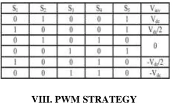
Here an auxiliary circuit consists of one switch and four diodes are used along with a full bridge configuration. The principle of operation of the proposed inverter is to generate five levels of output voltage, V/2, V, 0; -V/2 and –V. Using proper switching sequence in this modified circuit, five levels in output voltage is generated [10]. Table 1 shows the switching sequence used for generating five levels in the output voltage.
Table1: Switching sequence
VIII. PWM STRATEGY
and phase angle, but with different offset voltage magnitudes. The PWM strategy is shown in Fig.9.
Fig.9. Sine-triangle PWM
The switching patterns of the five level inverter are shown in Fig. 11.
Fig.10. switching patterns of the five level inverter Cascade Multilevel Inverter
The cascade multilevel inverter consists of a number of H-bridge inverter units with separate dc source for each unit and is connected in cascade or series Each H-bridge can produce three different voltage levels: +Vdc, 0 and –Vdc by connecting the dc source to ac output side by different combinations of the four switches S1, S2, S3, and S4. The ac output of each H-bridge is connected in series such that the synthesized output voltage waveform is the sum of all of the individual H-bridge outputs. By connecting sufficient number of H-bridges in cascade and using proper modulation scheme, a nearly sinusoidal output voltage waveform can be synthesized
Fig.11 Cascade multilevel inverter topology.
The number of levels in the output phase voltage and line voltage are 2s+1 and 4s+1 respectively, where s is the number of H-bridges used per phase. For example, three H-bridges, five H-bridges and nine H-bridges per phase are required for 7-level, 9-level and multilevel inverter respectively. a typical waveform produced by 7-level CMLI. The magnitude of the ac output phase voltage is the sum of the voltages produced by H-bridges.
INDUCTION MOTOR (IM)
An induction motor is an example of asynchronous AC machine, which consists of a stator and a rotor. This motor is widely used because of its strong features and reasonable cost. A sinusoidal voltage is applied to the stator, in the induction motor, which results in an induced electromagnetic field. A current in the rotor is induced due to this field, which creates another field that tries to align with the stator field, causing the rotor to spin. A slip is created between these fields, when a load is applied to the motor. Compared to the synchronous speed, the rotor speed decreases, at higher slip values. The frequency of the stator voltage controls the synchronous speed. The frequency of the voltage is applied to the stator through power electronic devices, which allows the control of the speed of the motor. The research is using techniques, which implement a constant voltage to frequency ratio. Finally, the torque begins to fall when the motor reaches the synchronous speed. Thus, induction motor synchronous speed is defined by following equation,
Where f is the frequency of AC supply, n, is the speed of rotor; p is the number of poles per phase of the motor. By varying the frequency of control circuit through AC supply, the rotor speed will change.
Power electronics interface such as three-phase SPWM inverter using constant closed loop Volts l Hertz control scheme is used to control the motor. According to the desired output speed, the amplitude and frequency of the reference (sinusoidal) signals will change. In order to maintain constant magnetic flux in the motor, the ratio of the voltage amplitude to voltage frequency will be kept constant. Hence a closed loop Proportional Integral (PI) controller is implemented to regulate the motor speed to the desired set point. The closed loop speed control is characterized by the measurement of the actual motor speed, which is compared to the reference speed while the error signal is generated. The magnitude and polarity of the error signal correspond to the difference between the actual and required speed. The PI controller generates the corrected motor stator frequency to compensate for the error, based on the speed error.
IX. SIMULATION RESLUTS:
Fig.12 Simulink model of five level inverter
Fig.13 Sine-triangle PWM
The switching technique adopted to generate the gate signals is obtained by comparing a reference signal with two carrier signals. The reference signal is a rectified sinusoidal signal and the two carrier signals are triangular waves having the same frequency and phase angle, but with different offset voltage magnitudes. The PWM strategy is shown in Fig.13.
Fig.14 Output voltage of the five level inverter
The output current of the five level inverter when fed from PV for a load R= 1 ohm is shown in Fig.14. It is seen that five levels are generated in the output for different loads using a single input.
Fig.15 output voltage of the PV array
The output voltage of the five level inverter when fed from PV for a load resistance of 10 ohms is shown in Fig.15.
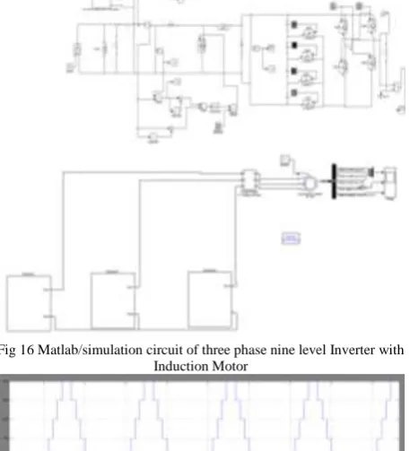
Fig 17 Simulation wave form nine level inverter output
The output current of the nine level inverter when fed from PV for a load R= 1 ohm is shown in Fig.17. It is seen that
five levels are generated in the output for different loads using a single input.
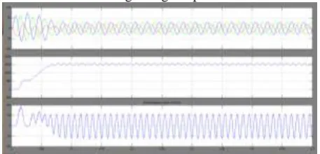
Fig 18 simulation wave form of three phase nine level inverter with induction motor stator current, speed and electromagnetic torque
X. CONCLUSION
In this project, the modeling and simulation of a solar PV/battery hybrid energy system with a five level inverter has been presented. The proposed system reduces both voltage & current THD and implements a reliable hybrid renewable energy system. The five-level inverter topology used in proposed system has less number of switches compared to conventional cascaded H-bridge configuration. Detailed simulation analysis is carried out to evaluate the dynamic performance of the proposed system under different worse case conditions. It is found from simulation results that the performance of the proposed renewable hybrid energy system is good for all the tested conditions for three phase nine level inverter with induction motor performance of stator current, speed and electromagnetic torque
REFERENCES
[1] S. Alepuz, S. Busquets-Monge, J. Bordonau, J. Gago, D. Gonzalez, and J. Balcells, ―Interfacing renewable energy sources to the utility grid using a three-level inverter,‖ IEEE Trans. Ind. Electron., vol. 53, no. 5, pp. 1504– 1511, Oct. 2006
[2] Sachin Jain and Vivek Agarwal, ―A single stage Grid connected inverter topology for solar PV systems with Maximum Power Point Tracking‖, IEEE Transactions on Power Electronics, vol22, issue.5, Publication year: 2007.
[3] Shagar Banu M, Vinod S, Lakshmi.S, ―Design of DC-DC converter for hybrid wind solar energy system‖,2012 International conference on Computing, Electronics and Electrical Technologies.
[4] Thanujkumar.Jala, G. Srinivasa Rao,‖ A novel nine level grid connected inverter for photovoltaic system‖ International journal of modern Engineering Research, vol.2, issue.2, March-April 2012, Page(s): 154-159
[5] J. Rodríguez, J. S. Lai, and F. Z. Peng, ʊMultilevel inverters: A survey of topologies, controls, and applications, IEEE Trans.
Ind. Electron., vol. 49, no. 4, pp. 724–738, Aug. 2002
[6] S. A. Khajehoddin, A. Bakhshai, P. Jain, ―The Application of the Cascaded Multilevel Converters in Grid Connected
Photovoltaic Systems,‖ IEEE Canada Electrical Power Conference, 25-26 Oct. 2007, pp. 296-301
[7] S. B. Kjaer, J. K. Pedersen, and F. Blaabjerg, ʊA review of singlephase grid connected inverters for photovoltaic modules, IEEE Trans. Ind. Appl., vol. 41, no. 5, pp. 1292–1306, Sep./Oct. 2000.
[8] L. M. Tolbert, F. Z. Peng, ―Multilevel Converters as a Utility Interface for Renewable Energy Systems,‖ IEEE Power Engineering Society Summer Meeting, Seattle, Washington, July 15-20, 2000, pp. 1271-1274
[9] M. Calais and V. G. Agelidis, ʊMultilevel converters for single-phase grid connected photovoltaic systems—An overview,
in Proc. IEEE Int. Symp. Ind. Electron., 1998, vol. 1, pp. 224–
229.
[10] Faete Filho, Yue cao, Leon M.Tolbert, ―11 level cascaded H bridge grid tied inverter interface with solar panels‖, Publication year: 2010
Authors Profile:
Mr.MEDINENI PRASANNA
CHOWDARY M.Tech student Scholar presently pursuing M.Tech in prestigious Sri Indu Institute of Engineering & Technology, Hyderabad, India.
Mrs. R.Manasa is presently working as
Assistant professor in prestigious Sri Indu Institute of Engineering & Technology, Hyderabad, India.
Mr. Suresh Ballala is presently working as Associate professor & HOD of Electrical & Electronics Engineering in prestigious Sri Indu Institute of Engineering & Technology, Hyderabad, India. He obtained M.Tech in Digital Electronics and Communication Systems from JNTUH. B.Tech from Basaveshwara Engg. College, Bagalkot, Karnataka University. He won Third prize in a seminar contest organized by Asia pacific telecommunications young professionals and students forum, Ministry of Information Technology in association with BSNL at IETE-. From last 17 years he is guiding the students in Enhancement of Embedded Systems.