ISSN (Print) : 2320 – 3765 ISSN (Online): 2278 – 8875
I
nternational
J
ournal of
A
dvanced
R
esearch in
E
lectrical,
E
lectronics and
I
nstrumentation
E
ngineering
(An ISO 3297: 2007 Certified Organization)
Website: www.ijareeie.com
Vol. 6, Issue 5, May 2017
Automatic Generation Control with Z-N
Tuned PID Controller in the Two Area Power
System with Energy Storage Unit
Pratap Chandra Pradhan1, Nibedita Satapathy2, Prasanta Kumar Pany3, Jayakrushna Moharana4
Associate Professor, Dept. of EE, DRIEMS, Cuttack, Odisha, India1
Assistant Professor, Dept. of EE, DRIEMS, Cuttack, Odisha, India2
Professor, Dept. of EE, ABIT, Cuttack, Odisha, India 3
Professor, Dept. of EE, HIT, BBSR, Odisha, India4
ABSTRACT: The Automatic Generation Control is the main control in power system to match the generation with
demand. Power system size and the type of load, makes the AGC more important. In this work Hydro plants and thermal plants are taken into consideration. Two models are developed using MATLAB/SIMULINK. Single area thermal power system is one. Similarly, thermal plant and hydro plant are considered as separate areas and they are connected with tie-line to form two area hydro thermal system. When the systems are subjected to load change of 1%, there is variation in frequency and tie-line power which can be reduced by using secondary controller. PID controller is used in this paper as secondary controller. The different controller parameters for single area and two area power system are tuned by Z–N method. The concept of SMES unit applied to AGC has also been made. Apart from the secondary controller, Superconducting Magnetic Energy Storage device is used for frequency control in two area power system. The results are compared to determine the performance of the system with SMES and different controllers using SIMULINK.
KEYWORDS: AGC, PID, SMES, ACE, Ziegler-Nichols (Z–N).
I. INTRODUCTION
ISSN (Print) : 2320 – 3765 ISSN (Online): 2278 – 8875
I
nternational
J
ournal of
A
dvanced
R
esearch in
E
lectrical,
E
lectronics and
I
nstrumentation
E
ngineering
(An ISO 3297: 2007 Certified Organization)
Website: www.ijareeie.com
Vol. 6, Issue 5, May 2017
active power source with fast response such as SMES is very effective in enhancing the expected performance of the system [12,13].
Literature survey shows that, the performance of the power system depends on the controller structure and the methods used to optimize the parameters of controller and also the use of SMES has been found outrightly.
So, this paper highlights the analysis of Single area thermal power system and AGC of a two-area hydrothermal power system considering storage unit like SMES in area-1. Area 1 consists of a nonreheat turbine and area 2 consists of a hydro unit.
In simulation, a step load variation of 1% of the nominal loading is considered in Single area as well as two area power system. For comparison, the following power systems are considered:
a) Single area Thermal power system i. Conventional integral controller ii.ZN-P, ZN-PI and ZN–PID controller.
From the result it observed that ZN –PID controller is superior than conventional controller, as the objective of this paper.
b) Two area hydro thermal power system i. ZN –PID controller without SMES, ii. ZN –PID controller with SMES in area-1.
From the result it observed that the performance of ZN –PID controller with SMES in area-1 is better than without SMES, as the other main objective of this paper.
The system parameters are given in the Appendix. Model of single area power system (thermal) is shown in figure 1. Two-area AGC system block diagram with SMES in area-1 is shown in figure 2.
II. MATERIAL AND METHOD A. Power system model
Single area thermal system
In a single area system, the role of the AGC is only to bring the frequency to the nominal value. This will be achieved using the secondary loop. Secondary loop uses the controller to change the reference power setting so as to change the speed set point. The controller gain needs to be tuned for better response of the system. In this paper Single area Thermal power system is considered. The model is developed using SIMULINK [15] which is shown in figure 1. The different types of controllers like Integral, P, PI, and PID are used in single area power system. The parameter values of P, PI, PID controllers for the power system are tuned by ZN method.
Two area hydro thermal system
An interconnected power system can be divided into number of control areas connected by tie-lines. In each control area, all generators are tightly coupled together to form a coherent group. Some of the areas in the power system are experimented having load disturbances of same magnitudes. Each control area should strive to deliver its own load and tie-lines permit electric power to flow between areas. Hence, a load disturbance in one of the areas influences the output frequencies of other areas and power flows on tie-lines. Due to the above the control system of the areas wants information about all areas to bring the frequency to its nominal value.
In present work, two area hydro-thermal model has been considered for AGC studies which is shown in figure 2. The model is developed using SIMULINK [1-2, 15].
B. Modeling of SMES in AGC
ISSN (Print) : 2320 – 3765 ISSN (Online): 2278 – 8875
I
nternational
J
ournal of
A
dvanced
R
esearch in
E
lectrical,
E
lectronics and
I
nstrumentation
E
ngineering
(An ISO 3297: 2007 Certified Organization)
Website: www.ijareeie.com
Vol. 6, Issue 5, May 2017
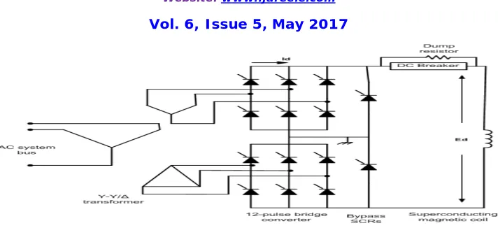
The control of the converter firing angle α provides the dc voltage appearing across the inductor to be
continuously varying within a certain range of positive and negative values. Initially the inductor is charged to its rated current Id0 by applying a small positive voltage. When the current meets its rated value, it is maintained to be constant by decreasing the voltage across the inductor to zero because the coil is superconducting.
By neglecting the converter and the transformer losses. The dc voltage is given below Ed = 2Vd0cosα - 2Id RC (1)
where Ed is the dc voltage applied to the inductor in kV, α is the firing angle in degrees, Id is the current flowing through the inductor in kA, RCis the equivalent commutating resistance in kΩ and Vd0 is the maximum circuit bridge voltage in kV. Charging and discharging of the SMES unit is controlled through the change of commutation
angle α. If α is less than 900, converter acts in the converter mode (charging mode) and if α is greater than 900, the converter acts in the inverter mode (discharging mode).
SMES control strategy
When power is to be pumped back into the grid in the case of a decrease in frequency, the control voltage Ed is to be negative because the current through the inductor and the thyristors cannot change its direction. The incremental change in the voltage applied to the inductor is expressed as
∆E = ACE
(2)
where, ΔEd is the incremental change in converter voltage; TDC is the converter time delay ; KSMES is the gain of the control loop and ACE1 is the input signal to the SMES control logic.
Figure1. SIMULINK model of single area power system(thermal)
ISSN (Print) : 2320 – 3765 ISSN (Online): 2278 – 8875
I
nternational
J
ournal of
A
dvanced
R
esearch in
E
lectrical,
E
lectronics and
I
nstrumentation
E
ngineering
(An ISO 3297: 2007 Certified Organization)
Website: www.ijareeie.com
Vol. 6, Issue 5, May 2017
Figure 3
.
SMES circuit diagram.The inductor current deviation is given in Eq. (3)
∆I =∆ (3)
In the present work, area control error (ACE) of area 1 is considered as the input signal to the SMES control logic (i.e., ACE1). The area control error of the two areas are expressed as
ACE = B ∆f +∆P , i, j = 1,2 (4)
Where Δfiis the change in frequency of area i and ΔPtieij is the change in tie-line power flow out of area i – j. So, from Eqs. (2) and (4),
∆E = (B ∆f +∆P ) (5)
Note that ACE1 = (B1Δf1 + ΔPtie12 ). However, it is presented in [12-13]that, the inductor current in the SMES unit will return to its nominal value very slowly only by use of Eq. (5). But, the inductor current must be restored to its nominal value very fast after a system disturbance so that it can respond to the next load disturbance instantly. Therefore, the inductor current deviation can be sensed and used as a negative feedback signal in the SMES control loop for current restoration to its nominal value for improvement. SIMULINK model of SMES unit with the negative inductor current deviation feedback is shown in figure 4. Therefore, the dynamic equations for the inductor voltage deviation and current deviation of the SMES unit is given below
∆E = [K (B ∆f +∆P )−K ∆I ] (6)
C. Controller structure
PID controllers are useful and most accepted controllers in industrial applications due to their robustness and easy to design and make economic. PID controllers provided in each area to control the frequency which is shown in figure 5.
III. TUNING OF PID CONTROLLER BY ZIEGLER -NICHOLS (Z-N) METHOD
The Ziegler–Nichols tuning method is a heuristic method of tuning a PID controller. It was developed in 1942 by John G. Ziegler and Nathaniel B. Nichols.
A. Ziegler - Nichols closed - loop tuning method
ISSN (Print) : 2320 – 3765 ISSN (Online): 2278 – 8875
I
nternational
J
ournal of
A
dvanced
R
esearch in
E
lectrical,
E
lectronics and
I
nstrumentation
E
ngineering
(An ISO 3297: 2007 Certified Organization)
Website: www.ijareeie.com
Vol. 6, Issue 5, May 2017
Figure 4. SIMULINK model of SMES unit
Figure 5 Structure of PID controller.
The Kp, Ki and Kd can be obtained for a system with feedback. The Ziegler-Nichols closed-loop tuning method is restricted to tuning processes that cannot run in an open-loop environment [10, 14].
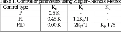
Determining the final gain value K is accomplished by finding the value of the proportional gain that causes the control loop to oscillate indefinitely at steady state. This means that the gains of the integral and derivative controller are set to zero. It tests the robustness of the Kp value so that it is optimized for the controller. One more important value associated with this proportional control tuning method is the ultimate period (T). The ultimate period is the time required to complete one full oscillation when the system is at steady state. These two parameters, K and T, are used to determine the loop-tuning constants of the controllers (P, PI, or PID). Put these values into the Ziegler-Nichols closed loop equations shown in table 1 and find out the necessary settings for the controller.
Table 1. Controller parameters using Ziegler–Nichols Method
Control type Kp Ki Kd
P 0.5 K - -
PI 0.45 K 1.2Kp/T -
PID 0.60 K 2Kp/ T Kp T /8
With the above method, the parameter values of K and T are obtained as 2.2735 and 0.9583 respectivelyfor single area thermal system. These two parameters, K and T, are used to determine the loop-tuning constants of the controller (P, PI, or PID) which is given in the table 2.
Table 2. Controller parameters for single area thermal system using Z-N method.
Control type Kp Ki Kd
P 1.1367 0 0
PI 1.023 1.2811 0
ISSN (Print) : 2320 – 3765 ISSN (Online): 2278 – 8875
I
nternational
J
ournal of
A
dvanced
R
esearch in
E
lectrical,
E
lectronics and
I
nstrumentation
E
ngineering
(An ISO 3297: 2007 Certified Organization)
Website: www.ijareeie.com
Vol. 6, Issue 5, May 2017
Similarly for two area hydro-thermal system with and without SMES the value of Kand T parameters are obtained as -1.4888 and 3.8 respectively. These two parameters, K and T, are used to determine the loop-tuning constants of the PID controller, which is given in the table 3.
Table 3. PID controller parameters using Z-N method.
IV. RESULTS AND DISCUSSIONS
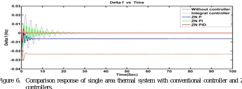
A. Comparison response of single area thermal system with conventional controller and ZN Tuned Controllers:
Figure 6 gives the simulated responses for the single area thermal system with conventional controller and ZN tuned controllers with 1% load disturbance. The conventional integral controller is tuned by trial and error method and its parameter value is taken as Ki = 0.79.
From the comparison response shown in Figure 6, it’s clear that minimum peak value and minimum settling time are achieved by ZN-PID controller than conventional controller or ZN-P or ZN-PI controller.
Figure 6. Comparison response of single area thermal system with conventional controller and ZN tuned controllers.
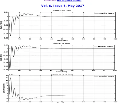
B. Response of two area hydro-thermal system with and without SMES Without SMES
The system is subjected to load disturbance of 1% in area-1(Thermal power plant) and area-2 (Hydro power plant). Its simulated response of frequency deviation and tie- line power deviation are shown in figure 7.
With SMES
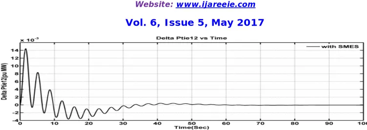
The system is subjected to load disturbance of 1% in area-1(Thermal power plant) and area-2 (Hydro power plant) and SMES is connected in area-1 alone. Its simulated response of frequency deviation and tie- line power deviation is shown in figure 8.
From the responses shown in figure 7 and 8, it can be observed that, the behavior of area frequencies and tie- line power have enhanced significantly in terms of deviation and settling time in the presence of SMES.
Control type Kp Ki Kd
ISSN (Print) : 2320 – 3765 ISSN (Online): 2278 – 8875
I
nternational
J
ournal of
A
dvanced
R
esearch in
E
lectrical,
E
lectronics and
I
nstrumentation
E
ngineering
(An ISO 3297: 2007 Certified Organization)
Website: www.ijareeie.com
Vol. 6, Issue 5, May 2017
ISSN (Print) : 2320 – 3765 ISSN (Online): 2278 – 8875
I
nternational
J
ournal of
A
dvanced
R
esearch in
E
lectrical,
E
lectronics and
I
nstrumentation
E
ngineering
(An ISO 3297: 2007 Certified Organization)
Website: www.ijareeie.com
Vol. 6, Issue 5, May 2017
Figure 8. Dynamic responses for Δf1, Δf2and ΔPtie12 with 1% step load disturbance in the thermal area and hydro area with Z-N tuned PID controller and SMES in thermal area.
V. CONCLUSION
The single area power system and two area power system were developed using SIMULINK. In single area power system, the comparison result shows that minimum peak value and minimum settling time are achieved by ZN-PID controller than conventional controller or ZN-P or ZN-PI controller. The PID secondary controllers for two area hydro-thermal system have been tuned using ZN method. It is evident that, the AGC performance of two area power system with SMES unit in the area-1 is improved. It is observed that, energy storage device like SMES, is able of taking up the momentary oscillations in the area frequencies and the tie-line powers following a load disturbance. It is further observed that ZN tuned PID controller with SMES provides better response in terms of less peak and less settling time.
APPENDIX A. System data
Kp1=Kp2= 120 HZ/MW, R1=R2= 2.4 HZ/P.U.MW, Tp1=Tp2 = 20s, TT= 0.3 s, T1= 41.6 s, T2= 0.513 s, T12= 0.0866, TR= 5 s, TW = 1 S, TG= 0.08 s, B1=B2= 0.4249, PR1=PR2=1200 MW,D1=D2= 8.333*10-3 p.u.MW/HZ.
B. SMES data
L = 2.65 H, Kid= 0.2 KV/KA, TDC= 0.03 s, KSMES = 100 kV/unit MW, Id0= 4.5 K..
REFERENCES
[1] O.I.Elgerd, Electric Energy Systems Theory – an introduction, 2nd ed., New Delhi, Tata McGraw Hill, 1983. [2] P. Kundur, Power System Stability and Control, eighth reprint, Tata McGraw-Hill, 2009.
[3] H. Bevrani, Robust Power System Frequency Control, Springer, 2009.
[4] N. Cohn, “Some aspects of tie-line bias control on interconnected power systems,” Amer. Inst. Elect. Eng. Trans., vol. 75, pp. 1415-1436, Feb. 1957.
[5] O. I. Elgerd and C. Fosha, “Optimum megawatt frequency control of multi area electric energy systems,” IEEE Trans. Power App. Syst., vol. PAS-89, no. 4, pp. 556–563, Apr. 1970.
[6] IEEE Committee Report, “Standard definitions of terms for automatic generation control on electric power systems”, IEEE Trans. Power App. Syst., vol. PAS-89, Jul./Aug. 1970.
[7] R. K. Green, “Transformed automatic generation control,” IEEE Trans. Power Syst., vol. 11, no. 4, pp. 1799–1804, Nov. 1996.
[8] Mohd. Hasan Ali, B. Wu and Roger A Dougal “An overview of SMES application in power and energy systems,” IEEE Transactions on Sustainable Energy, vol. 1, no 1, pp. 38-47, 2010.
[9] Praghnesh Bhatt , Ranjit Roy, S.P. Ghoshal,” Comparative performance evaluation of SMES–SMES, TCPS–SMES and SSSC–SMES controllers in automatic generation control for a two-area hydro–hydro system,” International Journal of Electrical Power and Energy Systems ,vol. 33, no. 10, pp. 1585–1597, 2011. [10] J.G. Ziegler, N. B. Nichols, “Optimum setting for automatic controllers,” Transactions of ASME, vol. 64, no.80, pp. 759–768, 1942.
[11] R.K. Sahu, S. Panda, N.K. Yegireddy, “A novel hybrid DEPS optimized fuzzy PI/PID controller for load frequency control of multi-area interconnected power systems,” Journal of Process Control, vol. 24, no.10, pp.1596–1608, 2014.
[12] R.J. Abraham, D. Das, A. Patra, “AGC of a hydrothermal system with SMES unit,” in: Proc of IEEE conf. GCC Conference (GCC), pp. 1–7, 2006.
[13] S. Banerjee, J.K. Chatterjee, S.C. Tripathy, “Application of magnetic energy storage unit as load-frequency stabilizer,” IEEE Transactions on Energy Conversion, vol. 5, no. 1, pp. 46–51, 1990.
[14] Kuo B.C., Automatic Control Systems. 7th ed. Englewood Cliffs, NJ: Prentice Hall; 1995. [15] Hadi Saadat ”Power System Analysis”, McGraw Hill; 2002.