Volume 8, No. 1, Jan-Feb 2017
International Journal of Advanced Research in Computer Science RESEARCH PAPER
Available Online at www.ijarcs.info
ISSN No. 0976-5697
Comparison of loading of Metamaterial on Patch and Ground of a Triangular Patch
Antenna
Dr. R. Gayathri Rajaraman
Assistant Professor, Department of Electronics & Communication Engineering, Annamalai University, Chidambaram, India
Abstract: Two different antenna models are presented in this paper They are designed with Spiral resonators (SR); One with SR on Ground and another with SR’s on Patch. In Model I, A compact dual band triangular patch antenna using a novel metamaterial structure in its ground plane is designed. The role of the metamaterial structure is to miniaturize the antenna, inducing multi resonances. The antenna resonates at 5.46, 6.02 GHz with adequate gains of 3.2, and 5.6 dBs respectively. Key Antenna parameters obtained from the simulator are presented along with detailed discussions. In Model II, A novel dual band triangular patch antenna designed using Spiral resonators (SR) in its patch is presented. The metamaterial structure (SR) used in this design effectively reduces the size of conventional patch resulting in dual resonances with wide apart spectras. The antenna is found to resonate at 10.38, 13.99 GHz with gains of 3.6 and 5.4 dBs respectively. The antenna has an Omnidirectional pattern and good directivity at the resonant bands. A comparitive remark is also presented.
Keywords: Microstrip patch antenna, linear polarization, wireless applications
I. INTRODUCTION
Over Recent years Microwave engineers turned their attention towards spiral resonators in the design of MPA. Microstrip patch antenna (MPA) has many remarkable features when compared with many wireless antennas like cheap, light weight, easy integration etc because of this features it finds application in almost all wireless system [1]. The design of such antennas is always a challenging task to designers as it should occupy minimum space but do the best performance during transmission and reception. There are many types of patches like rectangular, square, triangular, hexagonal, elliptical and so on. In this paper two triangular patches are modelled using a metamaterial (SR) and presented in different sections with elaborate discussions. The basic details about triangular patches are available in [2-6]. The MTM structure; Spiral Resonator is found to create miniaturisation when designed properly.
Metamaterials are artificially synthesized materials supporting backward waves with negative permeability, permittivity. This was originally proposed by Vessalago in 1968. Some advancements in design of MPA with MTM are seen in [7-14]. This paper is presented as four sections; The Conventional Design, Proposed Design I, II, Analysis and Conclusions
I Design of the Conventional Patch
[image:1.595.328.539.326.446.2]The antenna is designed with RT Duroid substrate with relative permittivity of 2.2 and a thickness of 62 mils. The top view is shown in Figure1. The inset feed with a microstrip line of 50 ohm impedance is carried out to make the antenna resonate at 6.6 GHz with -12.74 dB as in Figure 2.
[image:1.595.301.567.481.693.2]Fig. 1: Simulated MPA Model.
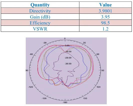
Fig. 2: Reflection Coefficient of the Proposed Antenna. Table 1 Simulated Parameters
Quantity Value
Directivity 3.9801
Gain (dB) 3.95
Efficiency 98.5
[image:1.595.115.209.677.766.2]VSWR 1.2
Fig. 3: Radiation Pattern of MPA
Fig. 4: Polar Plot (Gain) of the Proposed .
The gain has adequate co and cross po levels supporting linear vertical polarization. The directivity and VSwr are also adequate for the patch. This patch is modified and that is presented in the next section.
Design of the Proposed Antenna I
The conventional patch antenna is etched with an inverted U shaped slot besides etching a spiral resonator in its ground this leads to dual resonance.The values are shown in Table 2. The model is shown in Figures 5,6. The spiral resonators are found to create miniaturization up to λ/30. The design equations presented in this section holds good only if value of N, which is the number of turns of resonator, does not exceed a predefined integer value as given below.
+
+
−
=
)
(
2
)
(
maxs
w
s
w
l
Integer
N
SR … (1)The design equations for the spiral resonators are as follows
+ =
ω
π
µ
2 ln 2 1 2 0 SRavg SRavg SR l lL … (2)
(
)
∑
− = + + − + + = 1 1 2 2 2 1 1 ) ( 4 N n oSR l n s
N N s l C C ω
ω (3)
Where stands for width, s for spacing , N is an integer, n stands for number of turns, l stands for length while the expressions for lSRavg and Co are available in [9].
[image:2.595.51.229.58.197.2]Fig. 5: Top View of the Proposed Antenna.
Fig. 6: Ground View of the Proposed Antenna.
Table 2: Dimension of the Proposed Antenna.
Parameters Size (mm)
Substrate 60 x60 x1.524
Ground 60x 60
SR turns 8
Width 0.5
Distance 1
Thickness 0.002
Analysis of The Proposed Antenna I
The modified patch is found to resonate at two frequencies 5.46, 6.02 GHz with a return loss of -18.05, -13.15 dBs ; This is
[image:2.595.302.566.71.168.2]depicted in Figure 7. Further at this frequencies polar plots are simulated and are shown in Figures 8,9. The antenna has FBR values hence may be some attempts may be done to curtail back radiation in further research.
[image:2.595.331.537.278.422.2]Fig. 7: Radiation Pattern of the Proposed Antenna.
Fig.8: Polar plot of the Proposed Antenna.
[image:2.595.36.278.382.495.2] [image:2.595.58.253.426.762.2]Table 3: Simulated Antenna Parameters at 5.464 GHz.
Table 4:Simulated Antenna Parameters at 6.024 GHz.
Design of The Proposed Antenna II
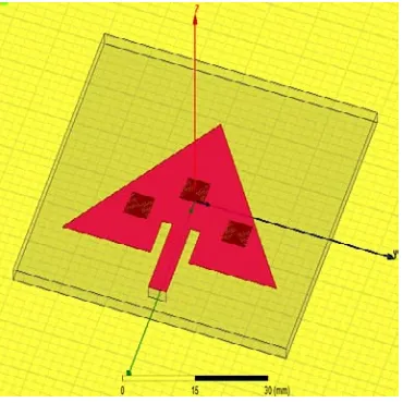
The conventional patch antenna (Designed with duroid substrate of 60 mil thickness) fed with a microstrip line is etched with three spiral resonators this is targetted to create dual resonances. The optimized dimensions are shown in Table 5. The model is shown in Figure 10. The spiral resonators are excellent structures aiding miniaturization up to
λ/30 where λ is free space wavelength.
[image:3.595.35.256.61.190.2]Fig. 10: Top View of the Proposed Antenna.
Table 5: Dimension of the Proposed Antenna.
Parameters Size (mm)
Substrate 60 x60 x1.524
Ground Size 60x 60
SR turns 10
Width 0.125
Distance 0.25
Thickness 0.002
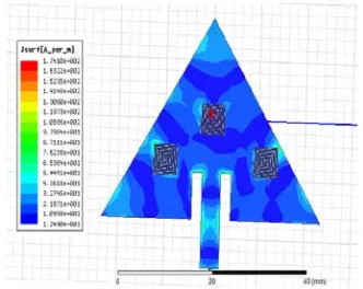
The proposed antenna resonates at two frequencies 10.38, 13.99 GHz with a return loss of -12.48, -21.87 dBs ; This is Shown in Figure 11. Further at this frequencies Radiation plots are simulated and are shown in Figures 12,14. The VSWR variation is shown in Figure 13. The surface current density is depicted to show that the current travels long path making antenna resonate at lower frequencies( Figures 15,16). Thus making the patch dual resonant in nature. The simulated antenna parameters are consilidated and are tabulated in Tables6,7.
Fig. 11:.Return Loss of the Proposed Antenna.
[image:3.595.70.255.453.638.2]Fig.12: Radiation Pattern of the Proposed Antenna.
Fig.13: VSWR of the Proposed Antenna.
[image:3.595.27.296.681.769.2]Fig.15: Surface Current Density on the Patch
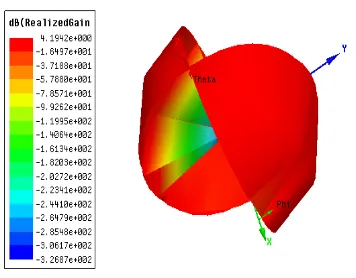
[image:4.595.302.558.73.146.2] [image:4.595.69.250.239.356.2]Fig. 16: Surface Current Density on the Patch
Fig. 17: Directivity of the Patch
Fig. 18: Directivity of the Patch
Table 6: Simulated Antenna Parameters at 10.38 GHz. No. Quantity Value Unit
1 Max U 0.28303 w/sr
2 Directivity 6.7781 dB 3 Efficiency 98
4 FBR 31.8
Table 7:Simulated Antenna Parameters at 13.39 GHz.
No. Quantity Value Unit
1 Max U 0.4284 w/sr
2 Directivity 7.131 dB
3 Efficiency 81.7
4 FBR 30.45
CONCLUSIONS
Spiral inductors can be effectively used in design of multi band antennas. Two proposal are presented in this paper; when used in Ground the FBR values are controlled; while on patch a wide apart spectras was got but with Increased FBR.
ACKNOWLEDGEMENTS
I thank the authorities of Annamalai university. I would like to thank my Guru, Dr. Khagindra Kumar Sood, Group Head, Satcom Systems and Technology Group (SSTG) & Satcom and Navigation Applications Area (SNAA), Space Applications Centre, Indian Space Research Organization, Ahmedabad, India
I thank the National Conference organizers “Innovative computational Techniques” on Feb 24, PSG College of Arts & Science for their suggestions. Also would like to thank the National Conference Organizer on Research and Development in Science Engineering and Technology -NCRDSET’17.at St. Anne’s College of Engineering, Parnruti. The present work is an extension of articles submitted to the above conferences.
REFERENCES
1. R. Garg, P. Bhartia, I. Bahl, A. Ittipiboon. Microstrip antenna design handbook. Artech House, London; 2001.
2. Jashwant S. Dahele and Kai Fong lee, “On the Resonant Frequencies of the Triangular patch antenna, IEEE Transaction on Antenna & Prop. 1987; 35,100-101p.1987.
3. K.F.Lee, K.M.Luk, J.SDahele, Characteristics of the Equilateral Triangular Patch Antenna. IEEE Transaction on Antennas & Prop.1989; 36, 1510-1518p.
4. Nirun Kumprasert and Wiwat Kiranon. Simple and Accurate Formula for the Resonant Frequency of the Equilateral Triangular Microstrip Patch Antenna,” IEEE Transaction on Antennas & Propagation.1994; 42, 1178-1179p.
K. Sharma and B. Bhat.Analysis of triangular microstrip resonator. IEEE Trans. Microwave Theory Tech. 1982; 30, 2029-2031p..
5. Shyh-TirngFang, Kin-Luong, Tzung- Wern Chiou. Bandwidth enhancement of inset-microstrip-line-fed equilateral triangular microstrip antenna. IEEE Transaction on Antenna & Propagation, 1988; 34, 2184-2186p.
6. V.G.Veselago.The electrodynamics of substances with simultaneously negative values of Ɛ, µ. Soviet Physics Uspeki. 1968; 10(4): 509–514p.
7. J.D.Baena, J.Bonache, F.Martin, R.Marques, et al. Equivalent circuit models for split ring resonators and complementary ring resonator coupled to planar transmission lines. IEEE Transactions on Microwave Theory & Techniques. 2005; 53(4): 1451–1461p.
[image:4.595.49.276.508.669.2]9. R.Gayathri, M.Anitha, K.K.Sood. Wideband gain-enhanced miniaturized metamaterial-based antenna for wireless applications. International Journal of Inventive Engineering and Sciences. 2014; 3(1): 20–22p.
10. R.Gayathri, M.Anitha, Alok K.Singhal, et al. Miniaturized patch antennas for wireless applications using slot-type complementary split ring resonator loading. International Journal of Applied Engineering Research. 2014; 9(22): 17371– 17381p.
11. R.Gayathri, K.K.Sood. Wideband miniaturized elliptical patch for wireless applications using novel Meta structures.
International Journal of Engineering and Techno Sciences. 2015; 1(1): 22–26p.
12. R. Gayathri, M. Anitha, Athrish Mukerjee, et al. Dual band, miniaturized, enhanced-gain patch antennas using differentially-loaded metastructures. Indian Journal of Science and Technology. 2015; 8(1): 11–16p.