Succinct Non-Interactive Zero Knowledge
for a von Neumann Architecture
Eli Ben-Sasson Technion
Alessandro Chiesa MIT
Eran Tromer Tel Aviv University
Madars Virza MIT
February 5, 2019
(updated version)
Abstract
We build a system that provides succinct non-interactive zero-knowledge proofs (zk-SNARKs) for pro-gram executions on a von Neumann RISC architecture. The system has two components: a cryptographic proof system for verifying satisfiability of arithmetic circuits, and a circuit generator to translate program executions to such circuits. Our design of both components improves in functionality and efficiency over prior work, as follows.
Our circuit generator is the first to beuniversal: it does not need to know the program, but only a bound on its running time. Moreover, the size of the output circuit dependsadditively(rather than multiplicatively) on program size, allowing verification of larger programs.
The cryptographic proof system improves proving and verification times, by leveraging new algorithms and a pairing library tailored to the protocol.
We evaluated our system for programs with up to 10,000instructions, running for up to 32,000 machine steps, each of which can arbitrarily access random-access memory; and also demonstrated it executing programs that usejust-in-time compilation. Our proofs are230bytes long at80bits of security, or288bytes long at128bits of security. Typical verification time is 5 milliseconds, regardless of the original program’s running time.
Contents
1 Introduction 3
1.1 Goal . . . 3
1.2 Prior work . . . 3
1.3 Limitations of prior work on zk-SNARKs . . . 4
1.4 Results . . . 5
1.5 Roadmap . . . 7
2 Preliminaries 7 2.1 Notation . . . 7
2.2 Arithmetic circuits . . . 8
2.3 Quadratic arithmetic programs . . . 8
2.4 Pairings . . . 9
2.5 zk-SNARKs for arithmetic circuits . . . 9
2.6 A von Neumann RISC architecture . . . 10
3 Our circuit generator 10 3.1 Past techniques . . . 11
3.2 Our construction . . . 12
4 Our zk-SNARK for circuits 14 4.1 The PGHR protocol and the two elliptic curves . . . 14
4.2 An optimized verifier . . . 15
4.3 An optimized prover . . . 16
4.4 An optimized key generator . . . 16
5 Evaluation 17 5.1 Performance of our circuit generator . . . 17
5.2 Performance of our zk-SNARK for circuit satisfiability . . . 19
5.3 Performance of the combined system . . . 19
5.4 Comparison with prior work . . . 21
6 Conclusion 22 A Other prior work 24 B The PGHR zk-SNARK protocol 25 C Additional experimental data 26 D zk-SNARKs forvnTinyRAM 30 D.1 Informal definition . . . 30
D.2 Construction . . . 31
E Case study:memcpywith just-in-time compilation 32
1
Introduction
1.1 Goal
Consider the setting where a client owns a public inputx, a server owns a private inputw, and the client wishes to learnz:=F(x, w)for a programF known to both parties. For instance,xmay be a query,wa confidential database, andFthe program that executes the query on the database.
Security. The client is concerned about integrityof computation: how can he ascertain that the server reports the correct outputz? In contrast, the server is concerned aboutconfidentialityof his own input: how can he prevent the client from learning information aboutw?
Cryptography offers a powerful tool to address these security concerns: zero-knowledge proofs[GMR89]. The server, acting as the prover, attempts to convince the client, acting as the verifier, that the followingNP statement is true: “there existswsuch thatz=F(x, w)”. Indeed:
• Thesoundnessproperty of the proof system guarantees that, if theNPstatement is false, the prover cannot convince the verifier (with high probability). Thus, soundness addresses the client’s integrity concern.
• Thezero-knowledgeproperty of the proof system guarantees that, if theNPstatement is true, the prover can convince the verifier without leaking any information aboutw(beyond was is leaked by the outputz). Thus, zero knowledge addresses the server’s confidentiality concern.
Moreover, the client sometimes not only seeks soundness but alsoproof of knowledge[GMR89, BG93], which guarantees that, whenever he is convinced, not only can he deduce that a witnesswexists, but also that the serverknowsone such witness. This stronger property is often necessary to security ifF encodes cryptographic computations, and is satisfied by most zero-knowledge proof systems.
Efficiency. Besides the aforementioned security desiderata, many settings also call forefficiencydesiderata. The client may be either unable or unwilling to engage in lengthy interactions with the server, or to perform large computations beyond the “bare minimum” of sending the inputxand receiving the outputz. For instance, the client may be a computationally-weak device with intermittent connectivity (e.g., a smartphone). Thus, it is desirable for the proof to benon-interactive[BFM88, NY90, BDSMP91]: the server just send the claimed outputz, along with a non-interactive proof string˜ πthat attests thatz˜is the correct output. Moreover, it is also desirable for the proof to besuccinct: π has sizeOλ(1)and can be verified in time Oλ(|F|+|x|+|z|), whereOλ(·)is some polynomial in a security parameterλ; in other words,πis very short and easy to verify (i.e., verification time doesnotdepend on|w|, norF’s running time).
zk-SNARKs. A proof system achieving the above security and efficiency desiderata is called a (publicly-verifiable)zero-knowledge Succinct Non-interactive ARgument of Knowledge(zk-SNARK). zk-SNARK constructions can be applied to a wide range of security applications, provided these constructions deliver good enoughefficiency, and support rich enoughfunctionality(i.e., the class of programsF that is supported).
Remark 1.1. In the zero-knowledge setting above, the client does not have the server’s input, and so cannot conduct the computation on his own. Hence, it is not meaningfulto compare “efficiency of outsourced computation at the server” and “efficiency of native execution at the client”, because the latter was never an option. Non-interactive zero-knowledge proofs (and zk-SNARKs) are useful regardless ofcross-over points.
Our goal in this paperis to construct
a zk-SNARK implementation supporting executions on a universal von Neumann RISC machine.
1.2 Prior work
• A zk-SNARK, with essentially-optimal asymptotics, for arithmetic circuit satisfiability, based onquadratic arithmetic programs(QAPs) [GGPR13]. They accompany their construction with an implementation.
• A compiler that maps C programs with fixed memory accesses and bounded control flow (e.g., array accesses and loop iteration bounds are compile-time constants) into corresponding arithmetic circuits. Ben-Sasson et al. [BCGTV13a] present three main contributions.
• Also a QAP-based zk-SNARK with essentially-optimal asymptotics for arithmetic circuit satisfiability, and a corresponding implementation. Their construction follows the linear-interactive proofs of [BCIOP13].
• A simple RISC architecture,TinyRAM, along with a circuit generator for generating arithmetic circuits that verify correct execution ofTinyRAMprograms.
• A compiler that, given a C program, produces a correspondingTinyRAMprogram.
Thus, both [PGHR13, BCGTV13a] have two main components: a zk-SNARK for a low-level language, and method to translate a high-level language to the low-level language. Finally, Braun et al. [BFRS+13] re-implemented the protocol of [PGHR13] and combined it with a circuit generator that incorporates memory-checking techniques [BEGKN91] to support random-access memory [BCGT13a].
Outsourcing computation to powerful servers. Numerous works [SBW11, SMBW12, SVPB+12, SBVB+13, CMT12, TRMP12, VSBW13, Tha13, BFRS+13] seek to verifiably outsource computation to untrusted pow-erful servers, e.g., in order to make use of cheaper cycles or storage. (See Appendix A for a summary.) We stress that verifiable outsourcing of computationsis not our goal. Rather, as mentioned, we study functionality and efficiency aspects ofnon-interactive zero-knowledge proofs, which are useful even when applied to relatively-small computations, and even with high overheads.
Compared to most protocols to outsource computations, known zk-SNARKs use “heavyweight” tech-niques, such as probabilistically-checkable proofs[BFLS91] and expensive pairing-based cryptography. The optimal choice of protocol, and whether it actually pays off compared to localnative execution, are complex, computation-dependent questions [VSBW13], and we leave to future work the question of whether zk-SNARKs are useful for the goal of outsourcing computations.
1.3 Limitations of prior work on zk-SNARKs
Recent work has made tremendous progress in taking zk-SNARKs from asymptotic theory into concrete implementations. Yet, known implementations suffer from several limitations.
Per-program key generation. As in any non-interactive zero-knowledge proof, a zk-SNARK requires a one-time trusted setup of public parameters: akey generator samples a proving key (used to generate proofs) and a verification key (used to check proofs). However, current zk-SNARK implementations [PGHR13, BCGTV13a] require the setup phase to depend on the programF, which ishard-codedin the keys. Key generation is costly (quasilinear inF’s runtime) and is thus difficult to amortize if conducted anew for each program. More importantly, per-program key generation requires,for each new choice of program, a trusted party’s help.
Limited support for high-level languages. Known circuit generators have limited functionality or effi-ciency: (i) [PGHR13]’s circuit generator only supports programs without data dependencies, since memory accesses and loop iteration bounds cannot depend on a program’s input; (ii) [BFRS+13]’s circuit generator allows data-dependent memory accesses, but each such access requires expensive hashing to verify Merkle-tree authentication paths; (iii) [BCGTV13a]’s circuit generator supports arbitrary programs but its circuit size scales inefficiently with program size (namely, it has sizeΩ(`T)for `-instructionT-step TinyRAM
programs). Moreover, while there are techniques that mitigate some of the above limitations [ZE13], these only apply in special cases, and not do address general data dependencies, a common occurrence in many programs.
support arbitrary programs and that efficiently scale with program size.
Generic sub-algorithms. The aforementioned zk-SNARKs use several sub-algorithms, and in particular elliptic curves and pairings. Protocol-specific optimizations are a key ingredient in fast implementations of pairing-based protocols [Sco05], yet prior implementations only utilize off-the-shelf cryptographic libraries, and miss key optimization opportunities.
1.4 Results
We present two main contributions: a new circuit generator and a new zk-SNARK for circuits. These can be used independently, or combined to obtain an overall system.
1.4.1 A new circuit generator
We design and build a new circuit generator that incorporates the following two main improvements.
(1)Our circuit generator isuniversal: when given input bounds`, n, T, it produces a circuit that can verify the execution ofanyprogram with≤`instructions, onanyinput of size≤n, for≤T steps. Instead, all prior circuit generators [SVPB+12, SBVB+13, PGHR13, BCGTV13a, BFRS+13] hardcoded the program in the circuit. Combined with a zk-SNARK for circuits (or anyNPproof system for circuits), we achieve a notable conceptual advance: once-and-for-all key generationthat allows verifying all programs up to a given size. This removes major issues in all prior systems: expensive per-program key generation, and the thorny issue of conducting it anew in a trusted way for every program.
Our circuit generator supports a universal machine that, like modern computers, follows thevon Neumann paradigm(program and data lie in the same read/write address space). Concretely, it supports a von Neumann RISC architecture calledvnTinyRAM, a modification ofTinyRAM[BCGTV13b]. Thus, we also support programs leveraging techniques such asjust-in-time compilationorself-modifying code[GESA+09, RP06]. To compile C programs to the vnTinyRAMmachine language, we ported the GCC compiler to this architecture, building on the work of [BCGTV13a].
See Figure 1 for a functionality comparison with prior circuit generators (for details, see [BFRS+13,§2]).
Supported functionality [SVPB+12, SBVB+13, PGHR13] [BCGTV13a] [BFRS+13] this work
side-effect free computations X X X X
data-dependent memory accesses × X X X
data-dependent control flow × X × X
self-modifying code × × × X
universality × × × X
Figure 1: Comparison of the functionality supported by our and previous circuit generators.
(2)Our circuit generator efficiently handleslargerarbitrary programs: the size of the generated circuitC`,n,T in terms of the bounds`, n, T, is
O (`+n+T)·log(`+n+T)gates.
Thus, the dependence on program size is additive, instead of multiplicative as in [BCGTV13a], where the generated (non-universal) circuit has sizeΘ (n+T)·(log(n+T) +`)
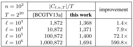
. As Figure 2 shows, our efficiency improvement compared to [BCGTV13a] is not merely asymptotic but yields sizable concrete savings: as program size`increases, our amortized per-cycle gate count is essentially unchanged, while that of [BCGTV13a] grows without bound, becoming orders of magnitudes more expensive.
n= 102 |C `,n,T|/T
improvement
T= 220 [BCGTV13a] this work
`= 103 1,872 1,368 1.4×
`= 104 10,872 1,371 7.9×
`= 105 100,872 1,400 72.1×
`= 106 1,000,872 1,694 590.8×
Figure 2: Per-cycle gate count improvements over [BCGTV13a].
expect, and find, that such circuit generators perform better than ours for programs that are already “close to a circuit”, and worse for programs rich in data-dependent memory accesses and control flow.
1.4.2 A new zk-SNARK for circuits
Our third contribution is a high-performance implementation of a zk-SNARK for arithmetic circuits. (3)We improve upon and implement the protocol of Parno et al. [PGHR13]. Unlike previous zk-SNARK implementations [PGHR13, BCGTV13a, BFRS+13], we do not use off-the-shelf cryptographic libraries. Rather, we create a tailored implementation of the requisite components: the underlying finite-field arithmetic, elliptic-curve group arithmetic, pairing-based checks, and so on.
To facilitate comparison with prior work, we instantiate our techniques for two specific algebraic setups: we provide an instantiation based on Edwards curves [Edw07] at 80 bits of security (as in [BCGTV13a]), and an instantiation based on Barreto–Naehrig curves [BN06] at 128 bits of security (as in [PGHR13, BFRS+13]).
On our reference platform (a typical desktop), proof verification is fast: at80-bit security, for ann-byte input to the circuit, verification takes4.7 + 0.0004·nmilliseconds,regardless of circuit size; at128-bit security, it takes4.8 + 0.0005·n. The constant term dominates for small inputs, and corresponds to the verifier’s pairing-based checks; in both cases, it isless than half the time for separately evaluating the12 requisite pairings of the checks. We achieve this saving by merging parts of the pairings’ computation in a protocol-dependent way — another reason for a custom implementation of the underlying math.
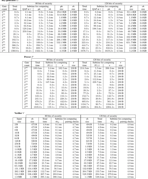
Key generation and proof generation entail a per-gate cost. For example, for a circuit with16million gates: at80bits of security, key generation takes81µs per gate and proving takes109µs per gate; at128bits of security, these per-gate costs mildly increase to100µs and144µs.
As in previous zk-SNARK implementations, proofs have constant size (independent of the circuit or input size); for us, they are230bytes at 80 bits of security, and288bytes at 128 bits of security.
Compared to previous implementations of zk-SNARKs for circuits [PGHR13, BCGTV13a, BFRS+13], our implementation improves both proving and verification times, e.g., see Figure 3.
80 bits of security 128 bits of security
[BCGTV13a] this work improvement [PGHR13] this work improvement
Key generator 306s 97s 3.2× 123s 117s 1.1×
Prover 351s 115s 3.1× 784s 147s 5.3×
Verifier 66.1ms 4.9ms 13.5× 9.2ms 5.1ms 1.8×
Proof size 322B 230B 1.4× 288B 288B (same)
Figure 3: Comparison with prior zk-SNARKs for a1-million-gate arithmetic circuit and a1000-bit input, running on our bench-marking machine, using software provided by the respective authors. Since [BFRS+13] is a re-implementation of [PGHR13], we only include the latter’s performance. (N= 5andstd<2%)
1.4.3 The two new components: independent or combined
PGHR13, BCGTV13a, BFRS+13], thus granting these systems universality: once-and-for-all key generation. Similarly, our zk-SNARK for circuits can replace the underlying zk-SNARKs in [PGHR13, BCGTV13a, BFRS+13], or be used directly in applications where a suitable circuit is already specified.
Combining these two components, we obtain a full system: azk-SNARK for proving/verifying correctness ofvnTinyRAMcomputations; see Figure 4 and Figure 5 for diagrams of this system. We evaluated this overall system for programs with up to10,000instructions, running for up to32,000steps. Verification time is, again, only few milliseconds, independent of the running time of thevnTinyRAMprogram, even when program size and input size are kilobytes. Proofs, as mentioned, have a small constant size. Key generation and proof generation entail a per-cycle cost, with a dependence on program size that “tapers off” as computation length increases. For instance, at128-bit security andvnTinyRAMwith a word size of32 bits, key generation takes210ms per cycle and proving takes100ms per cycle, for8K-instruction programs.
circuit generator
zk-SNARK key generator
proving key
verification key program size bound
time bound
input size bound universal circuit
OFFLINE PHASE (ONCE)
Key Generator
Figure 4:Offline phase (once).The key generator outputs a proving key and verification key, for proving and verifying correctness of any program execution meeting the given bounds.
witness map
zk-SNARK prover
zk-SNARK verifier
proving key program input
proof auxiliary
input
(nondeterminism)
accept/ reject
verif. key circuit
assignment
ONLINE PHASE (ANYNUMBEROFTIMES) Prover Verifier
program input
Figure 5:Online phase (any number of times).The prover sends a short and easy-to-verify proof to a verifier. This can be repeated any number of times, each time for a different program and input.
JIT case study: efficientmemcpy. Besides evaluating individual components, we give an example demon-strating the rich functionality supported by the integrated system. We wrote avnTinyRAMimplementation ofmemcpythat leveragesjust-in-time compilation(in particular,dynamic loop unrolling) to require fewer cycles. While ours is a simple case study, just-in-time compilation is a widely-used powerful technique with many applications, e.g., increasing the performance of interpreted programming languages such as JavaScript in web browsers [GESA+09] or Python [RP06]. As the efficiency of zk-SNARK implementations improves, more and more of these applications will become feasible.
1.5 Roadmap
In Section 2 we provide preliminaries. In Section 3 we describe our circuit generator. In Section 4 we describe our zk-SNARK for circuits. In Section 5 we evaluate our circuit generator and zk-SNARK, as well as the system resulting by combining the two. In Section 6 we conclude the paper.
2
Preliminaries
2.1 Notation
We denote byFa finite field andFnis the field of sizen; whennis prime, we identify elements ofFnwith integers modulon. Field elements are denoted with Greek letters (e.g.α, β, γ). We denote byF[z]the ring
of univariate polynomials overF, and byF≤d[z]the subring of polynomials of degree≤ d. Vectors are
denoted by arrow-equipped letters (such as~a); their entries carry an index but not the arrow (e.g.,a1ora2).
2.2 Arithmetic circuits
The circuits that we consider are not boolean butarithmetic. Given a finite fieldF, anF-arithmetic circuit
takes inputs that are elements inF, and its gates output elements inF. The circuits we consider only have bilinear gates.1Arithmetic circuit satisfiability is analogous to the boolean case:
Definition 2.1. Letn, h, lrespectively denote the input, witness, and output size. Thecircuit satisfaction problemof a circuit C: Fn×Fh → Fl with bilinear gates is defined by the relation RC = {(~x, ~a) ∈
Fn×Fh :C(x, ~a~ ) = 0l};2and its language isLC ={~x∈Fn:∃~a∈Fh, C(~x, ~a) = 0l}.
Our circuit generator reduces the correctness of program executions to arithmetic circuit satisfiability (see Section 3), and our zk-SNARK implementation produces/verifies proofs for this language (see Section 4).
All the arithmetic circuits we consider are over prime fieldsFp. In this case, when passing boolean strings as inputs to arithmetic circuits, wepackthe string’s bits into as few field elements as possible: given
s∈ {0,1}m, we use[[s]]m
p to denote the vector~x∈F
|m|p
p , where|m|p:=dm/blogpce, such that the binary representation ofxi ∈Fp is thei-th block ofdlogpebits ins(padded with0’s if needed). We extend the notation[[s]]mp to binary stringss∈ {0,1}nwithn < mbits via padding:[[s]]m
p := [[s0m−n]]mp . 2.3 Quadratic arithmetic programs
Our zk-SNARK leveragesquadratic arithmetic programs(QAPs), introduced by Gennaro et al. [GGPR13].
Definition 2.2. Aquadratic arithmetic programof size mand degreedover Fis a tuple(A, ~~ B, ~C, Z), whereA, ~~ B, ~Care three vectors, each ofm+ 1polynomials inF≤d−1[z], andZ ∈F[z]has degree exactlyd.
Like a circuit, a QAP induces a satisfaction problem:
Definition 2.3. Thesatisfaction problemof a size-mQAP(A, ~~ B, ~C, Z)is the relationR(A, ~~B, ~C,Z)of pairs
(~x, ~s)such that (i)~x ∈Fn,~s∈ Fm, andn ≤ m; (ii)xi = si fori ∈ [n](i.e.,~sextends~x); and (iii) the
polynomialZ(z)divides the following one:
(A0(z) +Pmi=1siAi(z))·(B0(z) +Pmi=1siBi(z))−(C0(z) +Pmi=1siCi(z)).
We denote byL(A, ~~B, ~C,Z)the language ofR(A, ~~B, ~C,Z).
Gennaro et al. [GGPR13] showed that circuit satisfiability can be efficiently reduced to QAP satisfiability (which can then be proved and verified using zk-SNARKs):
Lemma 2.4. There exist two polynomial-time algorithmsQAPinst,QAPwitthat work as follows. For any circuitC:Fn×Fh → Flwithawires andbgates,(A, ~~ B, ~C, Z) :=QAPinst(C)is a QAP of sizemand degreedoverFthat satisfies the following three properties.
• EFFICIENCY. It holds thatm=aandd=n+b+l+ 1.
• COMPLETENESS.For any(~x, ~a)∈ RC, it holds that(~x, ~s)∈ R(A, ~~B, ~C,Z), where~s:=QAPwit(C, ~x, ~a). • PROOF OF KNOWLEDGE. For any(~x, ~s)∈ R(A, ~~B, ~C,Z), it holds that(~x, ~a)∈ RC, where~ais a prefix of~s.
• NON-DEGENERACY. The polynomialsA0, . . . , Anare linearly independent. Moreover, the intersection of
the span ofA0, . . . , Anand the span ofAn+1, . . . , Amis trivial (only contains the zero polynomial).
1
A gate with inputsx1, . . . , xm∈Fisbilinearif the output ish~a,(1, x1, . . . , xm)i · h~b,(1, x1, . . . , xm)ifor some~a,~b∈Fm+1.
In particular, these include addition, multiplication, and constant gates.
Proof sketch. The third condition in Definition 2.3 implies thath1◦~s, ~A(ω)i · h1◦~s, ~B(ω)i=h1◦~s, ~C(ω)i
for all rootsω ofZ. In other words, membership inR(A, ~~B, ~C,Z) is characterized bydegZ = drank-1 quadratic constraints in the variable~s, and we can choose these constraints by choosing coefficients for the polynomialsA, ~~ B, ~C. We useb+lconstraints to encode the satisfiability of the arithmetic circuitC: one constraint per gate (enforcing its correct evaluation) and one constraint per circuit output (enforcing it to be zero). We then use an additional1 +nconstraints to meet the non-degeneracy condition:1·0 = 0and si·0 = 0fori= 1, . . . , n.3
Remark 2.5. The authors thank Ariel Gabizon [Gab19] and Bryan Parno for identifying a problem in an earlier version of Lemma 2.4. Previously, the lemma’s “non-degeneracy” condition merely required that A0, . . . , Anbe non-zero and distinct, which did not suffice for the security of the protocol in Appendix B. The current non-degeneracy condition yields a QAP degree ofd=n+b+l+ 1rather thand=b+l+ 1. The degree increase is negligible for all applications reported in this paper and [BCGG+14, BCTV14, CTV15, BCGTV15] becausen b(typically,n/b < 10−4), leaving performance results unaffected. A similar negligible increase holds for any circuit in which the number of inputsnis small compared to the number of gatesb, as is the case, e.g., for many circuits that verify cryptographic computations.
2.4 Pairings
The zk-SNARK constructions that we consider are based on cryptographicpairings, which we now introduce. LetG1andG2be two cyclic groups of orderr. We denote elements ofG1,G2 via calligraphic letters
such asP,Q. We writeG1andG2in additive notation. LetP1 be a generator ofG1, i.e.,G1={αP1}α∈Fr
(αis also viewed as an integer, henceαP1 is well-defined); letP2 be a generator forG2. Apairingis an
efficient mape:G1×G2 →GT, whereGT is also a cyclic group of orderr(which we write in multiplicative notation), satisfying the following properties: (i)bilinearity: for every nonzero elementsα, β ∈Fr, it holds thate(αP1, βP2) =e(P1,P2)αβ; (ii)non-degeneracy:e(P1,P2)is not the identity inGT.
For high-level discussions of zk-SNARK constructions, the choice of instantiation ofG1,G2,GT, as well as the choice of pairing e, does not matter. However, later, when discussing optimizations in our implementation (see Section 4), these choices matter a great deal.
2.5 zk-SNARKs for arithmetic circuits
A (preprocessing) zk-SNARKfor F-arithmetic circuit satisfiability (see, e.g., [BCIOP13]) is a triple of
polynomial-time algorithms(G, P, V), calledkey generator, prover, andverifier. The key generatorG, given a security parameterλand anF-arithmetic circuitC:Fn×Fh →Fl, samples aproving keypkand a verification keyvk; these are the proof system’s public parameters, which need to be generated only once per circuit. After that, anyone can usepkto generate non-interactive proofs for the languageLC, and anyone can use thevkto check these proofs. Namely, givenpkand any(~x, ~a)∈ RC, the honest proverP(pk, ~x, ~a) produces a proofπattesting that~x∈ LC; the verifierV(vk, ~x, π)checks thatπis a valid proof for~x∈ LC. A proofπis both a proof of knowledge, and a (statistical) zero-knowledge proof. The succinctness property requires thatπhas lengthOλ(1)andV runs in timeOλ(|~x|), whereOλhides a (fixed) polynomial inλ. Constructions. Several zk-SNARK constructions are known [Gro10a, Lip12, GGPR13, BCIOP13, PGHR13, BCGTV13a, Lip13]. The most efficient ones are based onquadratic span programs(QSPs) [GGPR13, Lip13] orquadratic arithmetic programs(QAPs) [GGPR13, BCIOP13, PGHR13, BCGTV13a]. We focused on QAP-based constructions, because QAPs allow for tighter reductions fromarithmeticcircuits (see Lemma 2.4). Concretely, we build on the QAP-based zk-SNARK protocol of Parno et al. [PGHR13] (see Section 4).
3
A more precise analysis shows that one only needs to add1 +n−rconstraints, whereris the rank of the(b+l)×(1 +n)
Remark 2.6(full succinctness). The key generatorGtakesCas input, and so its complexity is linear in
|C|. One could requireGtonot takeCas input, and have its output keys work forall(polynomial-size) circuits C; then, G’s running time would be independent of C. A zk-SNARK satisfying this stronger property isfully succinct. Theoretical constructions of such zk-SNARKs are known, based on various cryptographic assumptions [Mic00, Val08, BCCT13]. Despite achieving essentially-optimal asymptotics [BFLS91, BGHSV05, BCGT13b, BCGT13a, BCCT13] no implementations of them have been reported to date.4
2.6 A von Neumann RISC architecture
Ben-Sasson et al. [BCGTV13a] introducedTinyRAM, a Harvard RISC architecture with word-addressable memory. We modifyTinyRAM to obtain vnTinyRAM, which differs from it in two main ways. First,
vnTinyRAMfollows thevon Neumann paradigm, whereby program and data are stored in the same read-write address space; programs may use runtime code generation. Second,vnTinyRAMhas byte-addressable memory, along with instructions to load/store bytes or words.5
Besides the above main differences,vnTinyRAMis very similar toTinyRAM. Namely, it is parametrized by theword size, denotedW, and thenumber of registers, denotedK. TheCPU stateof the machine consists of (i) aW-bitprogram counter; (ii)Kgeneral-purposeW-bitregisters; (iii) a1-bitcondition flag. The full state of the machine also includesmemory, which is a linear array of2W bytes, and twotapes, each with a string ofW-bit words, and read-only in one direction. One tape is for aprimary inputxand the other for an
auxiliary inputw(treated as nondeterministic, untrusted advice).
In memory, an instruction is represented as a double word (one word for an immediate, and another for opcode, etc.). Thus, aprogramPis a list of address/double-word pairs specifying the initial contents of memory; all other memory locations assume the initial value of0.
At every time step, the machine executes the instruction encoded bypc-th double word in memory, where pcis program counterpc(with its lowest2W/8set to 0); every instruction incrementspcby2W/8(which is number of bytes in a double word), unless it explicitly modifiespc. The machine’s only input is via the input tapes and initial memory, and only output is via ananswerinstruction (which halts execution) having a single argumentA, representing the return value, whereA= 0means “accept”.
Language of accepting computations. Formally, when saying “prover/verify correct execution” we mean “membership in the language of accepting computations”. This language is defined as follows.
Definition 2.7. Fix bounds`, n, T. The languageL`,n,T consists of pairs(P,x)such that: (i)Pis a program with≤ `instructions, (ii)xis a primary input with≤ nwords, (iii) there exists an auxiliary inputws.t. P(x,w)accepts in≤T steps. We denote byR`,n,T the relation corresponding toL`,n,T.
For more details aboutvnTinyRAM, see [BCGTV13b].
3
Our circuit generator
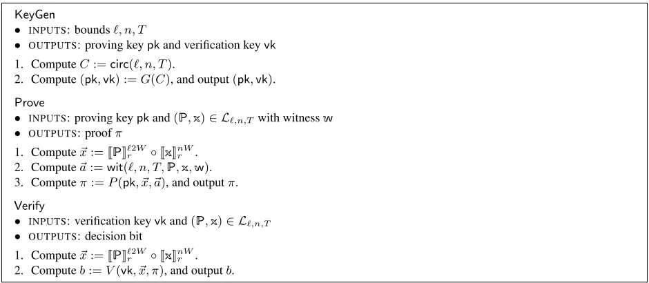
A circuit generator translates the correctness of suitably-bounded program executions into circuit satisfiability: given input bounds`, n, T, it produces a circuit that can verify the execution of anyprogram with≤ ` instructions, onanyinput of size≤n, for≤T steps. More precisely, using the notations[[s]]p(for packing the binary stringsinto field elements) and|s|p(for computing the number of field elements required to pack s) introduced in Section 2.2, we define a (universal) circuit generator forvnTinyRAMas follows.
4
In concurrent work, Ben-Sasson et al. [BCTV14] build a fully-succinct zk-SNARK, by following the approach of [BCCT13]. See [BCTV14] for a discussion about the tradeoffs between our construction and theirs.
5
Definition 3.1. A (universal) circuit generatorof efficiencyf(·)over a prime field Fp is a polynomial-time algorithmcirc, together with an efficientwitness mapwit, working as follows. For any program size bound`, time boundT, and primary-input size bound n, C := circ(`, n, T) is anFp-arithmetic circuit C:Fmp ×Fhp →Flp, form:=|`2W|p+|nW|pand someh, l, whereW is the word size (cf. Section 2.6). • EFFICIENCY. The circuitChasf(`, n, T)gates.
• COMPLETENESS. Given any programP, primary inputx, and witnesswsuch that (P,x),w∈ R`,n,T,
it holds that(~x, ~a)∈ RC, wherex~ := [[P]]`p2W ◦[[x]]nWp and~a:=wit(`, n, T,P,x,w).
• PROOF OF KNOWLEDGE. There is a polynomial-time algorithm such that, given any(~x, ~a)∈ RC, outputs a witnesswfor(P,x)∈ L`,n,T.
The circuitCoutput bycircisuniversalbecause it does not depend on the programPor primary input
x, but only on their respective size bounds`andn(as well as the time boundT). When combined with any proof system for circuit satisfiability (e.g., our zk-SNARK), this fact enables the generation of the proof systems’ parameters to be universal as well. Namely, it is possible to generate keys for all bound choices (e.g., in powers of2) up to some constant,once and for all; afterwards, one can pick the keys corresponding to bounds fitting a given computation. This avoids expensive per-program key generation and, more importantly, the need for a trusted party to conduct key generation anew for every program.
We construct a universal circuit generator with the following efficiency:
Theorem 3.2. There is a circuit generator of efficiencyf(`, n, T) =O (`+n+T)·log(`+n+T)
over any prime fieldFpof sizep >22W, whereW is the word size (cf. Section 2.6).
Remark 3.3. The primepis determined by the zk-SNARK construction with which the circuit generator is combined, and in our case is at least160bits (so that inverting discrete logarithms in related groups is hard). Thus, the conditionp >22W is not really a restriction, even for large word sizes (e.g.,W = 64). Regardless, Theorem 3.2 in fact holds foranyfieldF, but the construction, whenchar(F)≤22W, is more complex, and
our code does not currently support it.
3.1 Past techniques
Most of the difficulties that arise when designing a circuit generator have to do withdata dependencies. A circuit’s topology does not depend on its inputs but, in contrast, program flow and memory accesses depend on the choice of program and the program’s inputs. Thus, a circuit tasked with verifying program executions must be “ready” to support a multitude of program flows and memory accesses, despite the fact that its topology has already been fixed. Various techniques have been applied to the design of circuit generators.
Program analysis. In the extreme, if both the programP and its inputs(x,w)are known in advance, designing a circuit generator is simple: construct a circuit that evaluatesPon(x,w)by preparing the circuit’s topology to match the pre-determined program flow and memory accesses. But now suppose that onlyP is known in advance, but not its inputs(x,w). In this case, by analyzingPpiece by piece (e.g., separately examine the various loops, branches, and so on), one could try to design a circuitCPthat can handle different choices of inputs. Most prior circuit generators [SVPB+12, SBVB+13, PGHR13, BFRS+13] take this approach.
Multiplex every access. Computers are universal random-access machines (RAMs), so one approach of designing a universal circuit is to mimic a computer’s execution, building a layered circuit as follows. The i-th layer contains the entire state of the machine (CPU state and random-access memory) at time stepi, and layeri+ 1is computed from it by evaluating the transition function of the machine, handling any accesses to memory via multiplexing. While this approach supports arbitrary program flow, memory accesses are inefficiently supported; indeed, if memory hasSaddresses, the resulting circuit is huge: it has sizeΩ(T S).
Nondeterministic routing. Ben-Sasson et al. [BCGT13a] suggested usingnondeterministic routingon a Beneˇs network to support memory accesses efficiently; indeed, sorting and routing are ubiquitous techniques in fast simulation results between nondeterministic models of computation [Ofm65, Sch78, GS89, Rob91]. Our circuit generator builds on the techniques of [BCGT13a, BCGTV13a], so we briefly review the main idea behind nondeterministic routing.
Following [BCGT13a], Ben-Sasson et al. [BCGTV13a] introduced a simple computer architecture, called
TinyRAM, and constructed a routing-based circuit generator forTinyRAM. They define the following notions. ACPU state, denotedS, is the CPU’s contents (e.g., program counter, registers, flags) at a given time step. Anexecution tracefor a programP, time boundT, and primary inputxis a sequencetr = (S1, . . . , ST) of CPU states. An execution tracetrisvalidif there is an auxiliary inputwsuch that the execution trace induced byPrunning on inputs(x,w)istr.
We seek an arithmetic circuitCfor verifying thattris valid. We break this down by splitting validity into three sub-properties: (i)validity of instruction fetch(for each time step, the correct instruction is fetched); (ii)validity of instruction execution(for each time step, the fetched instruction is correctly executed); and (iii) validity of memory accesses(each load from an address retrieves the value of the last store to that address).
The first two properties are verified as follows. Construct a circuitCPso that, for any two CPU statesS andS0,CP(S, S0, g)is satisfied for some “guess”gif and only ifS0can be reached fromS(by fetching from
Pthe instruction indicated by the program counter inSand then executing it), forsomestate of memory. Then, properties (i) and (ii) hold ifCP(Si, Si+1,·)is satisfiable fori= 1, . . . , T−1. Thus,CcontainsT−1
copies ofCP, each wired to a pair of adjacent states intr.
The third property is verified via nondeterministic routing. Assume thatCalso gets as inputMemSort(tr), which equals to the sorting oftrby accessed memory addresses (breaking ties via timestamps), and write a circuitCmemso that validity of memory accesses holds ifCmemis satisfied by each pair of adjacent states
inMemSort(tr). (Roughly,Cmemchecks consistency of “load-after-load”, “load-after-store”, and so on.)
However,Cmerely gets some auxiliary inputtr∗, whichpurportsto beMemSort(tr). SoCworks as follows: (a)ChasT−1copies ofCmem, each wired to a pair of adjacent states intr∗; (b)Cseparately verifies that
tr∗=MemSort(tr)by routing on aO(TlogT)-node Beneˇs network. The switches of the routing network are set according to non-deterministic guesses (i.e., additional values in the auxiliary input), and the routing network merelyverifiesthat the switch settings induce a permutation; this allows for a very tight reduction. (Known constructions thatcomputethe correct permutation hide large constants in big-oh notation [AKS83].)
Past inefficiencies. After filling in additional details, the construction of [BCGTV13a] reviewed above gives a circuit of sizeΘ (n+T)·(log(n+T) +`)
= Ω(`·T). TheΩ(`·T)arises from the fact that all of the`instructions inParehardcodedinto each of theT−1copies ofCP. Thus, besides being non-universal, the circuit scales inefficiently as`grows (e.g., for`= 104,CP’s size is already dominated byP’s size).
3.2 Our construction
Instead of hardcoding the program Pinto each copy of the circuitCP, we follow the von Neumann paradigm, where the programPlies in the same read/write memory space as data. We ensure thatPis loaded into the initial state of memory, using a dedicated circuit; we then verify instruction fetch via thesamerouting network that is used for checking data loads/stores. While the idea is intuitive, realizing it involves numerous technical difficulties, some of which are described below.
Routing instructions and data. We extend an execution trace to not only include CPU states but also instructions:tr= (S1, I1, . . . , ST, IT)whereSiis thei-th CPU state, andIiis thei-th executed instruction. We seek an arithmetic circuitCthat checkstr, in this “extended” format, for the same three properties as above: (i)validity of instruction fetch; (ii)validity of instruction execution; (iii)validity of memory accesses.
As in [BCGTV13a], checking thattrsatisfies property (ii) is quite straightforward. Construct a circuit Cexeso that, given two CPU statesS, S0and an instructionI,Cexe(S, S0, I, g)is satisfied, for some guessg,
if and only ifS0can be reached fromS, by executingI, for some state of memory. Then,CcontainsT−1 copies ofCexe, each wired to adjacent CPU states and an instruction, i.e., thei-th copy isCexe(Si, Si+1, Ii, gi). Unlike [BCGTV13a], though, we verify properties (i) and (iii) jointly, via the same routing network. The auxiliary input now containstr∗= (A1, . . . , A2T), purportedly equal to the memory-sorted list ofboth instructions fetches and CPU states. (Since the programPlies in the same read-write memory as data, an instruction fetch fromPis merely a special type of memory load.) Thus, to check thattrsatisfies properties (i) and (iii), we designCto (a) verify thattr∗ =MemSort(tr)via nondeterministic routing, and (b) verify validity of all (i.e., instruction and data) memory accesses, via a new circuitCmem0 applied to each pair of adjacent itemsAi, Ai+1intr∗. Thus, in this approach,Pis never replicatedT times; rather, the fetching of
its instructions is verified together with all other memory accesses, one instruction fetch at a time.
Multiple memory-access types. Each copy ofCmem0 inspects a pair of items intr∗and (assumingtr∗ = MemSort(tr)) must ensure consistency of “load-after-load”, “load-after-store”, and so on. However, unlike in [BCGTV13a], the byte-addressable memory ofvnTinyRAMis accessed indifferent-sizedblocks: instruction-size blocks for instruction fetch; word-instruction-size blocks when loading/storing words; and byte-instruction-size blocks when loading/storing bytes. The consistency checks inCmem0 must handle “aliasing”, i.e., accesses to the same point in memory via different addresses and block sizes.
We tackle this difficulty as follows. Double-word blocks are the largest blocks in which memory is accessed (as instructions are encoded as double words; cf. Section 2.6). We thus let each item intr∗always specify a double-word, even if the item’s memory access was with respect to a smaller-sized block (e.g., word or byte). With this modification, we can letCmem0 perform consistency checks “at the double-word level”, and handling word/byte accesses by mapping them to double-word accesses with suitable shifting and masking.
Booting the machine. We have so far assumed that the programP, given as input toC,alreadyappears in memory. However, the circuitCsketched so far only verifies the validity oftrwith respect to a machine whose memory is initialized tosomestate, corresponding to the execution ofsomeprogram. ButC must verify correct execution of, specifically,P, and so it must also verify that memory is initialized to containP. SinceCdoes not explicitly maintain memory (not even the initial one) and only implicitly reasons about memory via the routing network, it is not clear howCcan perform this check.
We tackle this difficulty as follows. We further modify the the execution tracetr, by extending it with an initialbootsection, preceding the beginning of the computation, during which the input programPis stored into memory, one instructionPi at a time. This extends the length of bothtrandtr∗ from2T to`+ 2T, for `-instruction programs, and introduces a new type of item, “boot input store”, intr∗. Similarly, the routing network is now responsible for routing`+ 2T, rather than2T, packets.
Further optimizations. The above construction sketch (depicted in Figure 6) is only intuitive, and does not discuss other optimizations that ultimately yield the performance that we report in Section 5.1.
For example, while [BCGTV13a] rely on Beneˇs networks, we rely onarbitrary-size Waksman networks
Besides being closer to the information-theoretic lower bound ofN(logN−1.443), such networks eliminate costly rounding effects in [BCGTV13a], where the size of the network isdoubledifN is just above a power of2(since the height of a Beneˇs network is2dlogNe).
As another example, we wantCto not only support programs withexactly`instructions but also withat most`, and similarly for the boundnon the size of primary inputs (which our discussion has so far omitted); we work out the details forCto efficiently support such upper bounds.
Compiling tovnTinyRAM. To enable verification of higher-level programs, written in C, we ported the GCC compiler to thevnTinyRAMarchitecture, by modifying the Harvard-architecture, word-addressibleTinyRAM
C compiler of [BCGTV13a]. Given a C program, written in the same subset of C as in [BCGTV13a], the compiler produces the initial memory map representing a programP. This also served to validate the
vnTinyRAMarchitectural choices (e.g., the move to byte-addressing significantly, and added instructions, improved efficiency for many programs).
𝐶 𝐶 ⋮
boot
𝐶 𝐼
𝐼
𝑆 𝑆
𝑆
𝐼 ⋮ 𝐏 𝐏𝟐
𝐏⋮ℓ𝓁
𝑆
𝐶
⋮
𝐶
𝐴
𝐴 𝐴
𝐴
𝐴
𝐴
𝐴 ℓ𝓁 𝐴
𝐴
𝐴 ℓ𝓁 ⋮
𝐶 𝐶 𝐶 𝐶 𝐶 𝐶 𝐶
routing network
⋮
Figure 6: Outline of our universal circuit construction with the extended tracetron the left and (allegedly) its memory sorttr∗on the right. All inputs to the circuit, with the exception ofP(and the primary inputx, not shown), are nondeterministic guesses.
4
Our zk-SNARK for circuits
We discuss our second main contribution: a high-performance implementation of a zk-SNARK for arithmetic circuit satisfiability. Our approach is totailorthe requisite mathematical algorithms to thespecificzk-SNARK protocol at hand. While our techniques can be instantiated in many algebraic setups and security levels, we demonstrate them in two specific settings, to facilitate comparison with prior work. Later, in Section 5.2, we provide benchmarks for our zk-SNARK.
4.1 The PGHR protocol and the two elliptic curves
See Section 2.5 for an informal definition of a zk-SNARK for arithmetic circuit satisfiability. We improve upon and implement the zk-SNARK of Parno et al. [PGHR13]. For completeness the “PGHR protocol” is summarized in Figure 10, which provides pseudocode for its key generatorG, proverP, and verifierV. The construction is based on QAPs, introduced in Section 2.3.
A pairing is typically instantiated via apairing-friendly elliptic curve. Concretely, suppose that one uses a curveEdefined overFq, with embedding degreekwith respect tor, to instantiate the pairing. ThenGT is set toµr, the subgroup ofr-th roots of unity inF∗qk. The instantiation ofG1andG2 depends on the choice ofe;
typically,G1is instantiated as an order-rsubgroup ofE(Fq), while, for efficiency reasons [BKLS02, BLS04],
G2as an order-rsubgroup ofE0(Fqk/d)whereE0is ad-th twistofE. Finally, the pairingeis typically a
two-stage functione(P,Q) :=FE(ML(P,Q)), whereML:G1×G2 → Fkq is known asMiller loop, and FE:Fkq →Fkq is known asfinal exponentiationand mapsαtoFE(α) :=α(q
k−1)/r
.
As mentioned, we instantiate our techniques based on two different curves: an Edwards curve for the 80-bit security level (as in [BCGTV13a]) and a Barreto–Naehrig curve for the 128-bits security level (as in [PGHR13, BFRS+13]). We selected both the Edwards curve and Barreto–Naehrig curve so thatr−1 has high2-adic order(i.e.,r−1is divisible by a large power of2), because this was shown to improve the efficiency of the key generator and the prover [BCGTV13a].
Next, we describe the optimizations that we have applied to the zk-SNARK verifier (Section 4.2), then to the prover (Section 4.3), and, finally, to the key generator (Section 4.4).
4.2 An optimized verifier
The verifierV takes as input a verification keyvk, input~x∈Fnr, and proofπ, and checks ifπis a valid proof for the statement “~x∈ LC”. The computation ofV consists of two parts. First, usevkIC,0, . . . ,vkIC,n ∈G1
(part ofvk) and input~xto computevk~x :=vkIC,0+Pni=1xivkIC,i(see Step 1 in Figure 10c). Second, usevk, vk~x, andπ, to compute12pairings and perform the required checks(see Step 2, Step 3, Step 4 in Figure 10c). In other words,V performsO(n)scalar multiplications inG1, followed byO(1)pairing evaluations.
With regard toV’s first part, variable-base multi-scalar multiplication techniques can be used to reduce the number ofG1operations needed to computevk~x [BCGTV13a, PGHR13]. With regard toV’s second part, even if the pairing evaluations take constant time (independent of the input sizen), these evaluations are very expensive anddominate for smalln. Our focus here is to minimize the cost of these pairing evaluations.
When only making “black-box” use of a pairing, the verifier must evaluate12pairings(see Figure 10c),amounting to12Miller loops plus12final exponentiations. The straightforward approach is to compute these using a generic high-performance pairing library. We proceed differently: we obtain high-performance implementa-tions ofsub-componentsof a pairing, and then tailor their use specifically toV’s protocol.
Namely, first, we obtain state-of-the-art implementations of a Miller loop and final exponentiation. We utilizeoptimal pairings[Ver10] to minimize the number of loop iterations in each Miller loop, and, to efficiently evaluate each Miller loop, rely on the formulas of [ALNR11] (for Edwards curves) and [BGDMO+10] (for BN curves). As for final exponentiation, we use multiple techniques to speed it up: [SBCDPK09, GS10, FCnKRH12, KKC13].
Next, building on the above foundation, we incorporate inV the following optimizations.
(1) Sharing Miller loops and final exponentiations. The verifier V computes two products of two pairings(see Step 3 and Step 4 in Figure 10c).We leverage the fact that a product of pairings can be evaluated faster than evaluating each pairing separately and then multiplying the results [Sol03, Sco05, GS06, Sco07]. Concretely, in a product ofmpairings, the Miller loop iterations for evaluating each factor can be carried out in “lock-step” so to share a singleMiller accumulator variable, using oneFqk squaring per loop instead ofm.
In a similar vein, one can perform a single final exponentiation on the product of the outputs of them Miller loops, instead ofmfinal exponentiations and then multiplying the results. In fact, since the output of the pairing can be inverted for free (as the element isunitaryso that inverting equals conjugating [SB04]), the idea of “sharing” final exponentiations extends to a ratio of pairing products. Thus, in the verifier we only need to perform5, instead of12, final exponentiations.
8.1ms. We decrease this further as discussed next.
(2) Precomputation by processing the verification key. Of the12pairings the verifier needs to evaluate, only one is such that both of its inputs come from the proofπ. The other11pairings have one fixed input, either a generator ofG1orG2, or coming from the verification keyvk.
Whenever one of the two inputs to a pairing is fixed, precomputation techniques apply [GHS02, BLS03, Sco07], especially in the case when the fixed input is thebase pointin Miller’s algorithm. InV, this holds for9out of the11pairing evaluations. We thus split the verifier’s computation into anoffline phase, which consists of a one-time precomputation thatonlydepends onvk, and a many-timeonline phase, which depends on the precomputed values, input~x, and proofπ. More precisely, the result of the offline phase is aprocessed verification keyvk∗. Whilevk∗is longer thanvk, it allows the online phase to be faster.
E.g., at the 80-bit security level,vk∗decreases the total cost of pairing checks from8.1ms to4.7ms.
4.3 An optimized prover
The prover P takes as input a proving key pk (which includes the circuit C: Frn ×Fhr → Flr), input ~
x ∈ Fnr, and witness~a ∈ Fr. The prover P is tasked to produce a proof π, attesting that ~x ∈ LC. The computation of P consists of two main parts. First, compute the coefficients~hof the polynomial H(z) := A(z)BZ(z(z)−)C(z)(see Step 4 in Figure 10b), whereA, B, C∈Fr[z]are derived from the QAP instance (A, ~~ B, ~C, Z) :=QAPinst(C)and QAP witness~s:=QAPwit(C, ~x, ~a). Second, use the coefficients~h, QAP witness~s, and public keypkto computeπ(see Step 6 in Figure 10b).
With regard to the first part ofP, the coefficients~hcan be efficiently computed via FFT techniques [BCGTV13a, PGHR13]; our implementation follows [BCGTV13a], and leverages the high 2-adic order ofr−1for both of the elliptic curves we use.6 With regard toP’s second part, computingπ requires solving large instances of the following problem: given elementsQ1, . . . ,Qnall inG1 (or all inG2) and
scalarsα1, . . . , αn∈Fr, computeh~α, ~Qi:=α1Q1+· · ·+αnQn. Previous work [PGHR13, BCGTV13a] has leveraged generic multi-scalar multiplication to computeπ. We observe that these algorithms can be tailored to the specific scalar distributions arising inP. InP, the vector~αis one of two types: (i)~α∈Fd+1
r and represents the coefficients of the degree-dpolynomialH; or (ii)~α= (1◦~s◦δ1◦δ2◦δ3)∈F4+r m, for randomδ1, δ2, δ3∈Fr.
In case i, the entries in of ~α are random-looking. We use the Bos–Coster algorithm [BC89] due to its lesser memory requirements (as compared to, e.g., [Pip80]). We follow [BDLSY11]’s suggestions and achieve an assembly-optimized heap to implement the Bos–Coster algorithm.
In case ii, the entries in~sdepend on the input(C, ~x, ~a)toQAPwit; in turn,(C, ~x, ~a)depends on our circuit generator (Section 3). Using the above algorithm “as is” is inefficient: the algorithm works well when all the scalars have roughly the same bit complexity, but the entries in~chave very different bit complexity. Indeed,~αequals to~saugmented with a few entries; and~s, the QAP witness, can be thought of as the list of wire values inCwhen computing on(~x, ~a); the bit complexity of a wire value depends on whether it is storing a boolean value, a word value, and so on. We observe that there are only a few “types” of values, so that the entries ofα~ can be clustered into few groups of scalars with approximately the same bit complexity; we then apply the algorithm of [BC89] to each such group.
4.4 An optimized key generator
The key generatorGtakes as input a circuitC:Fnr ×Fhr →Flr, and is tasked to compute a proving keypk and a verification keyvk. The computation ofGconsists of two main parts. First, evaluate eachAi, Bi, Ciat
6
If the2-adic order ofr−1isithenFrcontains a primitive root of unity of order2i. Hence, one can use the classical radix-2
a random elementτ, where(A, ~~ B, ~C, Z) :=QAPinst(C)is the QAP instance. Second, use these evaluations to computepkandvk(see Step 3 and Step 4 in Figure 10a).
With regard toG’s first part, we follow [BCGTV13a] and again leverage the fact thatFrhas a primitive root of unity of large order. With regard toG’s second part, it is dominated by the cost of computingpk, which requires solving large instances of the following problem: given an element P in G1 or G2 and
scalarsα1, . . . , αn∈Fr, computeα1P, . . . , αnP. Previous work [PGHR13, BCGTV13a], used fixed-base windowing [BGMW93] to efficiently compute such fixed-base multi-scalar multiplications.
In our implementation, we achieve additional efficiency, in space rather than in time. Specifically, we leverage a structural property of QAPs derived from arithmetic circuits, in order to reduce the size of the proving keypk, as we now explain. Lemma 2.4 states that anF-arithmetic circuitC:Fn×Fh →Fl, with
αwires andβ gates, can be converted into a corresponding QAP of sizem=αand degreed≈βoverF.
Roughly, this is achieved in two steps. First, construct three matricesA,B,C∈F(m+1)×dthat encodeC’s
topology: for eachj∈[d], thej-th column ofA,Brespectively encodes the “left” and “right” coefficients of thej-th bilinear gate inC, while thej-th column of Cencodes the coefficients of the gate’s output. Second, lettingS ⊂Fbe a set of sized, defineZ(z) :=Qω∈S(z−ω)and, fori∈ {0, . . . , m}, letAibe the low-degree extension of thei-th row ofA; similarly define eachBiandCi. All prior QAP-based zk-SNARK implementations exploit the fact thatcolumnsin the matricesA,B,Care very sparse.
In contrast, we also leverage adifferentkind of sparsity: we observe that it is common forentire rows
ofA,B,Cto be all zeroes, causing the corresponding low-degree extensions to be zero polynomials.7 For instance, our circuit generator typically outputs a circuit for which the percentage of non-zero polynomials in
~
A, ~B, ~Cis only about52%,15%,71%respectively. The fact that many polynomials inA, ~~ B, ~Cevaluate to zero can be used towards reducing the size ofpk, by switching from a dense representation to a sparse one. In fact, we haveengineeredour circuit generator to reduce the number of non-zero polynomials inB~ as much as possible, because computations associated to evaluations ofB~ are conducted with respect to more expensiveG2 arithmetic, which we want to avoid as much as possible.8
5
Evaluation
We evaluated our system on a desktop computer with a 3.40 GHz Intel Core i7-4770 CPU (with Turbo Boost disabled) and 32 GB of RAM. All experiments, except the largest listed in Figure 8 and Figure 9, used a small fraction of the RAM. For the two largest experiments in Figure 9 we added a Crucial M4 solid state disk for swap space. Finally, while our code supports multi-threading, we ran all of our experiments in single-thread mode, for ease of comparison with prior work.
5.1 Performance of our circuit generator
In Section 3 we described our universal circuit generator; we now benchmark its performance.
Parameter choices. The circuit generator supports the architecturevnTinyRAM, which is parametrized by two quantities: theword sizeW and thenumber of registersK(see Section 2.6). We report performance for a machine withK = 16registers, and two choices of word size:W = 16andW = 32. Also, a circuit generator is defined relative to a prime fieldFp(see Definition 3.1) and its efficiency may in principle depend onp; since our construction has thesamenumber of gates for anypwithp >22W (a condition that holds for any cryptographically-largep), in the discussion below we do not have to worry about the value ofp.
7E.g., if thei-th wire never appears with a non-zero coefficient as the “left” input of a bilinear gate, then thei-th row ofAis zero,
and thusAiis the zero polynomial.
8
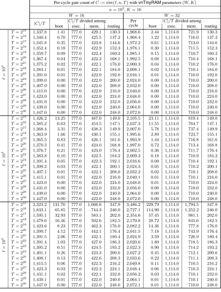
Per-cycle gate count ofC:=circ(`, n, T)withvnTinyRAMparameters(W, K) n= 102,K= 16
W = 16 W = 32
|C|/T |C|/Tdivided among cyclePer |C|/Tdivided among
boot exec. mem. routing boot exec. mem. routing
`
=
10
3 T= 220 1,367.4 0.04 777.0 422.2 168.1 1,992.5 0.08 1,114.0 710.4 168.1 T= 224 1,399.0 0.00 777.0 422.0 200.0 2,024.0 0.00 1,114.0 710.0 200.0 T= 228 1,431.0 0.00 777.0 422.0 232.0 2,056.0 0.00 1,114.0 710.0 232.0
`
=
10
4 T= 220 1,370.3 0.41 777.0 424.0 168.8 1,997.0 0.72 1,114.0 713.4 168.8 T= 224 1,399.2 0.03 777.0 422.1 200.1 2,024.3 0.05 1,114.0 710.2 200.1 T= 228 1,431.0 0.00 777.0 422.0 232.0 2,056.0 0.00 1,114.0 710.0 232.0
`
=
10
5 T= 220 1,399.7 4.12 777.0 442.1 176.4 2,041.5 7.19 1,114.0 743.9 176.4 T= 224 1,401.1 0.26 777.0 423.3 200.6 2,027.2 0.45 1,114.0 712.1 200.6 T= 228 1,431.1 0.02 777.0 422.1 232.0 2,056.2 0.03 1,114.0 710.1 232.0
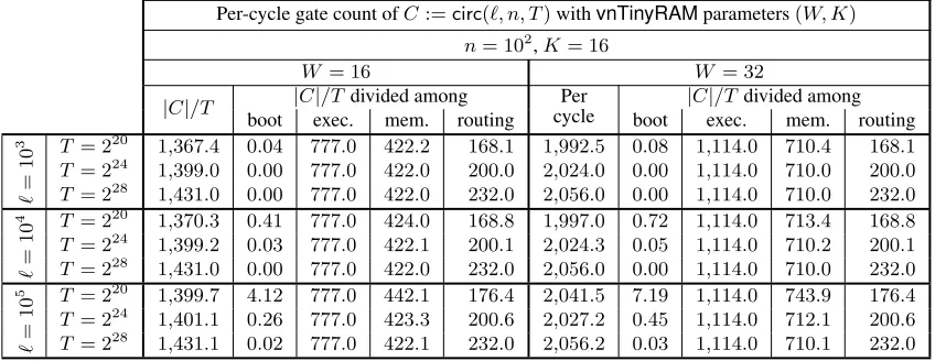
Figure 7:Performance of our circuit generator:per-cycle gate counts inC:=circ(`, n, T)for different choices of(`, n, T)and
vnTinyRAMparameters(W, K).
Methodology. Theorem 3.2 provides an asymptotic efficiency guarantee: it states that our circuit generator has efficiencyf(`, n, T) =O (`+n+T)·log(`+n+T)
. To understand concrete efficiency, we “uncover” the constants hidden in thebig-ohnotation. By studying the number of gates in various subcircuits of the generated circuitC:=circ(`, n, T), we computed the following (quite tight) upper bound onC’s size:
(12 + 2W)·`+ (12 +W)·n+|Cexe| ·T+ (|Cmem|+ 4 logH−1.82)·H
whereH := (`+n+ 2T)is the “height” of the routing network, and
• for(W, K) = (16,16):|Cexe|= 777and|Cmem|= 211; and • for(W, K) = (32,16):|Cexe|= 1114and|Cmem|= 355.
In Figure 7, we give per-cycle gate counts (i.e.,|C|/|T|) for various choices of(`, n, T); we also give sub-counts divided among program/input boot, CPU execution, memory checking, and routing. (See Figure 11 in Appendix C for an extended table with additional data.)
Discussion. We first go through the size expression, to understand it: The first two terms,(12 + 2W)·`+ (12 +W)·n, correspond to the pre-execution boot phase, during which an`-instruction program and an
n-word primary input are loaded into the machine. The term|Cexe| ·T corresponds to theT copies ofCexe
used to verify each CPU transition, given the fetched instruction and two CPU states. The term|Cmem| ·H
corresponds to theHcopies ofCmemused to verify consistency on the memory-sorted trace. Finally, the
term(4 logH−1.82)·H corresponds to the routing network for routingHpackets (two gates for each of(2 logH−0.91)·Hbinary switches). Note thatH = (`+n+ 2T)because boot needs`+nmemory stores (one for each program instruction and primary input word) and execution needs2Tmemory accesses (1 instruction fetch and 1 data store/load per execution cycle).
The gate counts in Figure 7 demonstrate the additive (instead of multiplicative) dependence on program size of our universal circuit pays off. For example, for(W, K) = (32,16), a 100-fold increase in program size, from` = 103 to` = 105, barely impacts the per-cycle gate count: forT = 220, it increases from 1,992.5to only2,041.5. Indeed, the cost of program size is incurred, once and for all, during the machine boot; Figure 7 shows that the per-cycle cost of machine boot diminishes asT grows.
Second,less than half ofC’s gates are dedicated to verifying accesses to random-access memory, while the majority of gates are dedicated to verifying execution of the CPU; indeed, almost always,|Cexe|T > 12|C|.
Put otherwise,C, which verifies an automaton with random-access memory (vnTinyRAM), has size that is less than twice that for verifying an automaton with the same CPU but no random-access memory at all. Moreover, note that the size ofCexe appears quite tight: for example, with(W, K) = (32,16), it has size
5.2 Performance of our zk-SNARK for circuit satisfiability
In Section 4 we described our zk-SNARK implementation; we now benchmark its performance.
Methodology. We provide performance characteristics for each of the zk-SNARK algorithms,G,P andV, at the 80-bit and 128-bit security levels. We benchmark the system as follows.
(1)The key generatorGtakes as input an arithmetic circuitC:Fnr ×Fhr →Flr. Its efficiency mostly depends on the number of gates and wires inC, because these affect the size and degree of the corresponding QAP (see Lemma 2.4). Thus, we evaluateGon a circuit with2i gates and2iwires fori∈ {10,12, . . . ,24}(and fixedn=h=l= 100). In Figure 8 we report the resulting running times and key sizes, asper-gate costs.
(2)The proverP takes as input a proving keypk, input~x∈Fn
r, and witness~a∈Fhr. Its efficiency mostly depends on the number of gates and wires inC(the circuit used to generatepk); we thus evaluateP on the proving keys output byG, for the same circuits as above. In Figure 8 we report the resulting running times, as per-gate costs, and (constant) proof sizes.
(3)The verifierV takes as input a verification keyvk, input~x∈Fnr, and proofπ. Its efficiency depends only on~x(since the size of~xdetermines that ofvk). Thus, we evaluateV on a random input~x∈Fn
r of2ibytes fori∈ {2,4, . . . ,20}. In Figure 8 we report the resulting running times, along with corresponding key sizes. For completeness, Figure 12 in Appendix C reports the unnormalized measurements and additional informa-tion (e.g., times for various subcomputainforma-tions).
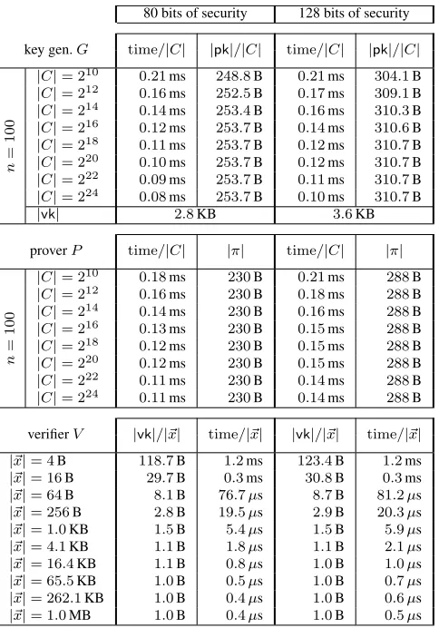
Discussion. The data demonstrates that our zk-SNARK implementation works and scales as expected, as long as sufficient memory is available (e.g., on a desktop computer with 32GB of DRAM: up to16million gates); also, as expected, the higher security level entails higher costs. Key generation takes about10ms per gate ofC; the size of a proving key is about300B per gate, and the size of a verification key is about1B per byte of input toC. Running the prover takes11ms to14ms per gate. For ann-byte input, proof verification time isc1n+c0, wherec0is a few milliseconds andc1is a few tenths of microseconds.
Remark 5.1. Another factor affecting the efficiency ofGandP is the number of non-zero polynomials in the QAP instance obtained from the circuitC(see Section 4.4). In Figure 8 we reported worst-case numbers in this respect: we only used circuits whose QAP hasno non-zero polynomials. In general, QAP with more zero polynomials make the key generator and prover faster; in particular, the circuits output by our circuit generator induce QAP instances with many zero polynomials, so that the numbers reported in Section 5.3 are somewhat better than what one would expect by merely multiplying the per-gate costs of Figure 8 with the number of gates in the circuit output by the circuit generator.
5.3 Performance of the combined system
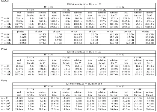
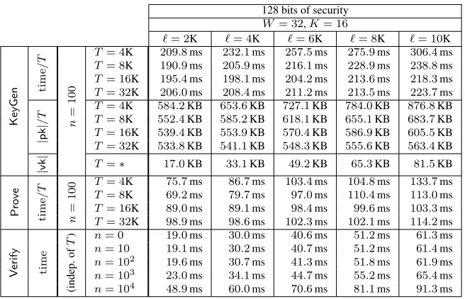
As discussed, our circuit generator (Section 3) and zk-SNARK for circuits (Section 4) can be used indepen-dently, or combined to obtain a zk-SNARK forvnTinyRAM. For completeness, in Appendix D.2 we spell out how these two components can be combined. Here we report measured performance of this combined system, at the 128-bit security level, and for a word sizeW = 32and number of registersK = 16.
Methodology. A zk-SNARK forvnTinyRAM is a triple of algorithms(KeyGen,Prove,Verify). Given bounds`, n, T (for program size, input size, and time), the efficiency ofKeyGenandProvedepends on `, n, T, while that ofVerifyessentially depends only on`, n. Thus, we benchmark the system as follows.
80 bits of security 128 bits of security
key gen.G time/|C| |pk|/|C| time/|C| |pk|/|C|
n
=
100
|C|= 210 0.21ms 248.8B 0.21ms 304.1B
|C|= 212 0.16ms 252.5B 0.17ms 309.1B
|C|= 214 0.14ms 253.4B 0.16ms 310.3B
|C|= 216 0.12ms 253.7B 0.14ms 310.6B
|C|= 218 0.11ms 253.7B 0.12ms 310.7B
|C|= 220 0.10ms 253.7B 0.12ms 310.7B
|C|= 222 0.09ms 253.7B 0.11ms 310.7B
|C|= 224 0.08ms 253.7B 0.10ms 310.7B
|vk| 2.8KB 3.6KB
proverP time/|C| |π| time/|C| |π|
n
=
100
|C|= 210 0.18ms 230B 0.21ms 288B
|C|= 212 0.16ms 230B 0.18ms 288B
|C|= 214 0.14ms 230B 0.16ms 288B
|C|= 216 0.13ms 230B 0.15ms 288B
|C|= 218 0.12ms 230B 0.15ms 288B
|C|= 220 0.12ms 230B 0.15ms 288B
|C|= 222 0.11ms 230B 0.14ms 288B
|C|= 224 0.11ms 230B 0.14ms 288B
verifierV |vk|/|~x| time/|~x| |vk|/|~x| time/|~x|
|~x|= 4B 118.7B 1.2ms 123.4B 1.2ms
|~x|= 16B 29.7B 0.3ms 30.8B 0.3ms
|~x|= 64B 8.1B 76.7µs 8.7B 81.2µs
|~x|= 256B 2.8B 19.5µs 2.9B 20.3µs
|~x|= 1.0KB 1.5B 5.4µs 1.5B 5.9µs
|~x|= 4.1KB 1.1B 1.8µs 1.1B 2.1µs
|~x|= 16.4KB 1.1B 0.8µs 1.0B 1.0µs
|~x|= 65.5KB 1.0B 0.5µs 1.0B 0.7µs
|~x|= 262.1KB 1.0B 0.4µs 1.0B 0.6µs
|~x|= 1.0MB 1.0B 0.4µs 1.0B 0.5µs
Figure 8:Performance of our zk-SNARK for arithmetic circuit satisfiability:per-gate costs of the key generator and prover for various circuit sizes; and per-byte costs of the verifier for various input sizes. (N = 10andstd<1%)
For completeness, Figure 13 in Appendix C reports the unnormalized measurements and additional infor-mation, such as times for various subcomputations (e.g., subtimes for the circuit generator and zk-SNARK). Discussion. The measurements demonstrate that, on a desktop computer, our zk-SNARK forvnTinyRAM
scales up to computations of32,000machine cycles, for programs with up to10,000instructions. Key generation takes about200ms per cycle; the size of a proving key is500KB to650KB per cycle, and the size of a verification key is a few kilobytes in total. Running the prover takes100ms to200ms per cycle. Verification times remain a few milliseconds, even for inputs and programs of several kilobytes.
Program-specificvk. The time complexity ofVerifyisO(`+n), so verification time grows with program size. This is inevitable, becauseVerifymustreada programP(of at most`instructions) and inputx(of at mostnwords) in order to check, via the given proofπ, if(P,x)∈ L`,n,T (cf. Definition 2.7). However, this is inconvenient, e.g., when one has to verify many proofs relative to different inputs to thesameprogramP.
In our zk-SNARK it is possible to amortize this cost as follows. GivenvkandP, one can derive, in time O(`), aprogram-specificverification keyvkP, which can be used to verify proofs relative to any input toP. Subsequently, the time complexity ofVerifyfor any inputx(toP) is onlyO(n),independentof`. Essentially, one can pre-compute the program-specific part ofvk~x(see Step 1 in Figure 10c), so that, later, one only needs to compute the input-dependent part ofvk~xand combine it withvkP. (Conversely, it is also possible to derive aninput-specificverification key, for verifying proofs relative to the same input to different programs.)

![Figure 10: The zk-SNARKways. First, it does not assume that protocol of Parno et al. [PGHR13]](https://thumb-us.123doks.com/thumbv2/123dok_us/7895579.1310498/25.612.44.577.202.661/figure-zk-snarkways-does-assume-protocol-parno-pghr.webp)