PID Controller Based Automatic Reactive
Power Control of a Wind-Diesel Hybrid Power
System
SubhraChandan Behera
1, G.KChoudhary
2, R.K Mandal
3P.G student[Control System],Dept. of EE, NIT,Patna, India1
Professor Dept. of EE, NIT,Patna, India2
Assistant Professor, Dept. of EE, NIT,Patna, India3
ABSTRACT
:
The study investigates the application of PID controller approach to stabilise the reactive power control of a Hybrid wind-diesel system .The above system consists of a synchronous generator for diesel generator,Induction generator for wind system, a STATIC VAR COMPENSATOR and Automatic voltage regulator for stabilizing of load terminal Bus.Here by controlling the firing angle SVC and gains of PID controller the voltage profile at load terminal is got improved. The performance of the Hybrid system with PID controller and without PIDcontroller is investigated by MATLAB simulation software.KEYWORDS: Induction generator,synchronous generator,staticvar compensator, Thyristor Controlled Reactor
I. INTRODUCTION
The need of power is continuously increasing day by day. The conventional fossil fuel power is unable to mitigate the the demand in today‟s date.Therefore today‟s technology wants a power delivered to be reliable and should be eco -friendly in nature. There by renewable sources is found to be more efficient.One of them is wind-diesel Hybrid power system.[1-3].The advantage of Hybrid power .The advantage of Hybrid power is that it continuously uses power generation as well as non-polluting wind energy. In hybrid power generation there can be more than one electrical generation .basically Synchronous generator is used for diesel power and Induction Generator is used for wind power. Induction generator have advantage over synchronous generator as it is less in cost ,less maintaince, rugged etc. but again its main disadvantage is that it needs reactive power for operation. Now with the increasing amount of non-linear Load the power quality issue has made the power system unstable. The power quality issue include voltage flicker, maintain reactive power,Harmonics etc,.Although different power quality equipment i.e like Active power filter,static synchrous compensator have been used [4-6]but due to their high cost its use has been limited. In order to mitigate cost issue static varcompensator(SVC) which uses thyristor phase controlled technology still a cost-effective solution to mitigate power quality issue[7-8].
In this paper a standalone hybrid power system is taken for a case study. During adverse condition voltage may decreases or increases in order to overcome voltage instability a PID based automatic reactive controller is designed with SVC which will helps to improve the voltage profile. The system state equation has been obtained as different block Diagrams.The Voltage deviation error has been used to eliminate reactive power insufficiency of the plant. The mathematical model of the Hybrid is shown in the section 2.This Hybrid model model is simulated using matlab Simulink environment . At Last comparison of result between this Hybrid-wind diesel model with SVC without PID controller and with PID controller is shown in section.
II. SVC SYSTEM CONFIGURATION
know that the phase angle between the two end voltage which is determined by real component line current is independent of shunt compensation. So we can add a reactor instead of capacitor to decrease the voltage in transmission line[8].Instead of using any devices like circuit breaker we can use thyristor valve to increases voltage control more efficiently.This is method is known as static varcompensaton(SVC).The basic reactive component of SVC is a shunt reactor and shunt capacitor. Thesereactor are varied by using thristor switching.
B. Basic description of static varcompensator(SVC):- Svc can be one of the following type 1. Thyristor Controlled Reactor(TCR)
2. TCR plus Fixed Capacitor(FC) 3. ThyristorSwitched Capacitor(TSC) 4. TSC plus TCR
The fourth one is very popularly used. Fig.1 shows an one line diagram of SVC in transmission Line. The idea is to sense voltage of the line and make the line stable by injecting inductance or capacitance depending on the signal generated by circuit by Automatic Voltage Regulator(AVR).so the gating signal will depend on the AVR signal.By controlling the conduction time of thyristor we can control voltage in each cycle. That‟s why this type of control is very fast and accurate.
Fig1.Typical SVS system
C. Reactive power compensation through SVC:-The two function of svc is to absorb or to generate reactive power. Generally thyristor switched capacitor(TSC) are used for absorb of reactive power where asThyristor controlled reactor (TCR) for generation of reactive power purpose TSC provides harmonics free control where as TCR gives continueous control of reactive power with SVC we can provide a good voltage profile with sufficient speed of response under transient condition.Now a days the SVC system is applied in all transmission system developments.
III. MATHEMATICAL MODEL OF WIND-DIESEL SYSTEM
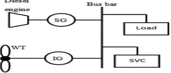
Fig. 2 Proposed schematic diagram of hybrid wind-diesel system
The excitation time constant is smaller than prime mover timr constant and its transient decay is much faster. The reactive balance equation at steady state is
∆QSVC+∆QSG= ∆QIG+∆QL…………(1)
Where Assuming the change in load reactive power is equal to ∆QL
Due to load the system reactive power increases by the amount ∆QSVC+∆ QSG The net reactive power can be written as
∆Qnet=∆QSVC+∆ QSG- ∆QIG-∆QL…..(2)
This power will increases the terminal voltage In two ways.
1) It increases the electromagnetic absorbtion(Em) of the induction generator(IG) at rated d/dt (Em). 2)It increases the reactive load consumption of the system.
This can be represent mathematically as
ΔQSG +ΔQSVC−ΔQL – ΔQIG = d/dt (ΔEM) + DVΔV….(3)
The electromagnetic energy stored in I.G is given by EM= 1/2L𝐿𝑚𝐼𝑚2=
Vt
4π𝑓𝑋𝑚……….(4)
Where, IM, LM, and XM, represents the current, inductance, and reactance of the Induction Generator respectively.Here f=system frequency
From eqr(4), ΔEM can be written as
ΔEM = EM− EoM= 2(EoM/𝑉𝑡o) Δ𝑉𝑡 ………(5)
where𝐸𝑀𝑜 and 𝑉𝑡𝑜 represents nomial value of electromagnetic energy stored I.G and terminal voltage.
When the voltage increase all connected reactive power loads increased by 𝐷𝑣= 𝜕QL
𝜕𝑉𝑡 (per unit kilovolts) The reactive power loadcan be expressed as[10]QL=C1Vq…….(6)
Where C1 is the constant of the loadand the exponent depends on the type of the load. For a small perturbation load and voltage charecterstics represented as
ΔQL/ΔVt = q (QoL/Vt o)...(7) Where QoLis the load reactive power
ΔQSG +ΔQSVC−ΔQL−ΔQIG= 2E o
M/ (Vt o
QR) d/dt (ΔVt) + DVΔVt...(8)
Where QR is the system power rating.The term EoM /QR can also be written as EoM/QR= 1/ (4πfkr) = HR………(9)
Where the term kR refers the ratio of the system reactive-power rating to rated magnetizing reactive power of IG.Substituringin Eqr(9) in (8) we will get
ΔQSG +ΔQSVC −ΔQL–ΔQIG= 2HR/V tod/dt (ΔV) + DVΔV to….(10)
Taking Laplace Transform Both sides
ΔVt(s) =KV/ (1 + sTV)×[ΔQSG(s) +ΔQSVC(s)−ΔQL(s)−ΔQIG(s)]…(11)
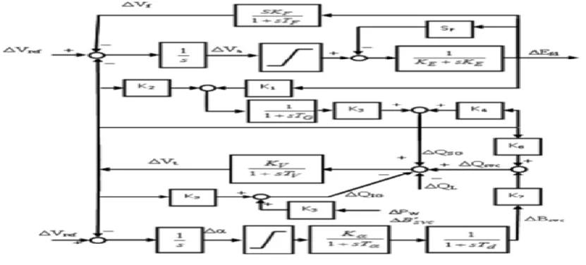
The complete block diagram of above mathematical equation is shown in fig.3
Fig 3 complete block diagram of hybrid diesel-wind system
Where Tv= ,Kv= 1
𝐷vUnder transient condition QSG = (EqVcos δ− V 2)/X
D……….…..(12)
For small perturbation, (12) can be written as ΔQSG = (Vtcos δ/Xd) ΔEq+{(Eqcos δ-2Vt)/Xd}ΔVt…..(13)
In Laplace transform, (13) can be written as ΔQSG(s) = K3ΔEq(s) + K4ΔV (s) ………….(14)
Where K3 = (V cos δ)/Xd AndK4 =Eqcos δ− 2V/Xd………(15)
The reactive power supplied by the SVC is given by:-
For small perturbation, (19) in the Laplace-transform form can be written as:- ΔQSVC(s) = K6ΔV (s)+ K7ΔBSVC(s)……….(17)
Where K6 =2BSVC .The flux linkage equation [12] of the round rotor synchronousmachine for small perturbation is given as d/dt (ΔEq) = (ΔEfd−ΔEq)/Td……….…(18)
In (17),ΔEq is given byΔEq=𝑋𝑑 𝑋𝑑 ′ ΔEq‟-
𝑋𝑑 −𝑋𝑑 ′
𝑋𝑑 ′ 𝑐𝑜𝑠 δ ΔV………..(19)
For small changes, (18), using (17) in the Laplace-transform form, can be written as:-
(1 + sTG)ΔEq = K1ΔEfd(s) + K2ΔV (s)…..(20) WhereTG = (XdTdo) /Xd………(21)
K1 =Xd/Xd………...(22)
K2 = {(Xd− XD) cos δ} /Xd...(23)
for small perturbation, reactive power absorbed by IG, QIG in terms of generator terminal voltage, and generator parameters can be written as
ΔQIG = K5ΔV (s)………(24) Where K5=
2VXeq
𝑅𝑦2+𝑋𝑒𝑞2RY =RP− Req ,where Rp= 𝑅2′
𝑠 (1 − 𝑠)
Then the state space model o reactive power control of the hybrid wind-diesel X = Ax+ Bu + Ed
Where A=[ΔEfdΔVfΔVaΔEqΔBsvcΔVt] U=[ΔVref]
d=[ΔQl]
IV. WIND-DIESEL SYSTEM DATA
In order to execute our Hybrid wind-diesel system we have taken some reference parameters such as Diesel capacity, wind capacity, Load capacity etc. which is listed below in table.1. The optimum gain setting of PID parameters is also listed in this table.
Table.1 System parameters
Diesel capacity 150(KW)
Wind capacity 150(KW)
Load capacity 250(KW)
Synchronous Generator PSG(pu Kw)
QSG(pu KVAR) EqPu
ᵟ
0.4 0.2 .96 21.05 Induction Generator PIG(pu Kw)QIG(pu KVAR ) S
r1,r2 in pu
Pl(Pu Kw) Ql(pu KVAR) Pf lag
1 .75 .8
Gain of PID controller Kp,Ki,Kd
35,5238, 35
V. RESULTS AND DISCUSSION
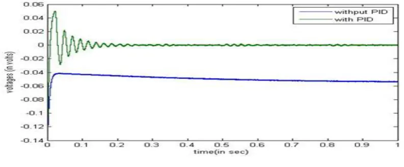
Simulation results of above system is shown in fig.6,fig.7 and in fig8. The effectiveness of proposed scheme is done through a step change in load reactive power.
A.Comparison of terminal voltage without PID and with PID:-In fig.6 the Terminal voltage of SVC is shown with and without PID controller. The effectiveness of using PID results in improvement of voltage at load side can be seen from the results.
Fig 4 Voltage without PID and with PID
B.
Reactive power of I.G:-In fig 7 the reactive power of I.G is shown with same PID and without PID controller.The improvemt of reactive power of I.G can be seen at load side.The damping is reduced after 3sec.VI .CONCLUSION
This paper investigates the improvement ofvoltage profile of a Hybrid wind diesel renewable set via considering a transfer function model approach.This model consists of a Synchronous generator driven by diesel engine and a induction generator driven by wind turbine and a thyristorcontrolled Staticvar compensator.The state space equation was developed for the above model.It was shown that this model need reactive power to improve its voltage profile.For the above purpose a PID controller is incorporated. The reactive power at load side is tested using step change of load reactive power.Finally by simulation results it was shown that by using the above controller not only we mitigate reactive power deficiency but also the damping is reduced
.
REFERENCES
[1] Pena, R., Cardenas, R., Proboste, J., Clare, J., Asher, G.: „Wind–diesel generation using doubly fed induction machines‟, IEEE Trans. Energy Convers., 2008, 23, (1), pp. 202–214.
[2] Sebastian, R.: „Modeling and simulation of a high penetration wind– diesel system with battery energy storage‟, Elect. Power Energy Syst.,2001, 33, (3), pp. 767–774.
[3] Saha, T.K., Kastha, D.: „Design optimization and dynamic performance analysis of a standalone hybrid wind–diesel electrical power generation system‟ IEEE Trans. Energy Convers., 2010, 25, (4), pp. 1209–1217
[4 ]L. H. Tey, P. L. So, and Y. C. Chu, “Improvement of power quality using adaptive shunt active filter,” IEEE Trans. Power Del., vol. 20, no. 2, pp. 1558–1568, Apr. 2005.
[5] García-Cerrada, P. García-González, R. Collantes, T. Gómez, and J. Anzola, “Comparison of thyristor-controlled reactors and voltagesource inverters for compensation of flicker caused by arc furnaces,” IEEETrans. Power Del., vol. 15, no. 4, pp. 1225–1231, Oct. 2000.
[6] M. E. Ortuzar, R. E. Carmi, J. W. Dixon, and L. Moran, “Voltage source active power filter based on multilevel converter and ultracapacitor DC link,” IEEE Trans. Ind. Electron., vol. 53, no. 2, pp. 477–485,Apr. 2006.
[7] B.-R. Lin and C.-H. Huang, “Implementation of a three-phase capacitor clamped active power filter under unbalanced condition,” IEEE Trans.Ind. Electron., vol. 53, no. 5, pp. 1621–1630, Oct. 2006.
[8] M.Prasad, R.S. Moni, P.Halvarsson, "Systems Aspects on Enhanced Stability using Static VAR Compensation (SVC) and Thyristor controlled series capacitor (TCSC)", Transmission & Distribution in 2000 Technical conference February 1996, pp. 15-19.
[9] Sharma, P., Bhatti, T.S.: „Performance investigation of isolated wind– diesel hybrid power systems with WECS having PMIG‟, IEEE Trans.Ind. Electron., 2013, 60, (4), pp. 1630–1637.
[10] Bansal, R.C.: „Automatic reactive power control of isolated wind–diesel hybrid power systems‟, IEEE Trans. Ind. Electron., 2006, 53, (4), pp. 1116–1126.