A MIMO Antenna Decoupling Network Composed of Inverters
and Coupled Split Ring Resonators
Luyu Zhao*, Le Liu, and Yuan-Ming Cai
Abstract—A decoupling network for a pair of strongly coupled MIMO antennas is presented. The decoupling network is composed of two inverters and two split ring resonators (SRRs) that are also coupled. By properly transforming the mutual admittance of the original coupled antennas and properly designing the coupling between the two SRRs, more than 20 dB isolation between the two antennas can be achieved while their respective matching performances remain good. To validate the concept, a microstrip decoupling network is designed and implemented for a pair of wideband printed monopole antenna elements. Measurement results have demonstrated that nearly 10% bandwidth for 20 dB isolation can be achieved. Measured radiation patterns have demonstrated a significant reduction of the correlation coefficient, which makes the proposed technique a promising candidate for both current and future generations of MIMO-enabled mobile terminals.
1. INTRODUCTION
Dramatic advances in next-generation communication systems have inspired portable and compact mobile terminals with increased spectrum and power efficiency. According to the well-known Shannon’s theorem, to improve the spectrum efficiency of a communication system, the best way is to use the multiple-input-multiple-output (MIMO) technology. This technology uses multiple antennas at both transmitter and receiver to improve the channel capacity by severalfold. Therefore, compact and broadband multi-antenna systems are required for future high-capacity mobile terminals [1–3].
As the wireless devices are becoming smaller and thinner, multiple antennas in portable terminals have to be implemented in a limited volume of space. As a consequence, the spacing between antennas is quite limited. This limited spacing will not only increase spatial correlation but also lead to strong mutual coupling between antennas. High spatial correlation will result in correlated channels and decreased channel capacity, whereas strong mutual coupling reduces radiated power and thus reduces signal-to-noise ratio and eventually the channel capacity. This issue has drawn great attention to the academia as well as many world leading companies. The solutions include meta-material based decoupling [4–7], passive network based decoupling [8–11] and parasitic structures or elements decoupling [12, 13].
This paper presents the design of a decoupling network formed by inverters and SRRs. Decoupling and matching conditions for the decoupling network will be derived. The admittance matrix of two coupled antennas is transformed such that the real part ofY12is zero at center frequency by inserting a
transmission line at each port to achieve better performances. For illustration purpose, a detailed design process is presented with a practical wideband MIMO antenna pair as an example. In this example, the decoupling network is implemented by microstrip resonators with the center frequency of 2.45 GHz and decoupling fractional bandwidth (FBW) around 10%. Simulated current distributions and measured
Received 12 June 2017, Accepted 7 October 2017, Scheduled 23 November 2017
* Corresponding author: Luyu Zhao ([email protected]).
radiation patterns are also shown. A significant reduction of envelope correlation coefficient calculated based on measurement data shows a promising application of the proposed decoupling network in MIMO and diversity antennas for advanced wireless terminals. Compared to [11], open loop resonators are used as the decoupling network instead of shorted quarter wavelength resonators, which gets rid of via holes and is more convenient to fabricate.
2. DESIGN THEORY
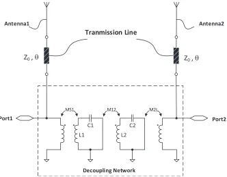
As shown in Figure 1, it is obvious that a pair of any coupled antennas can be represented by a 2×2 admittance matrix as:
YA=
YA
11 Y12A
YA
21 Y22A
(1)
whose entries, in general, are complex. Consider a lossless decoupling network whose admittance matrix is expressed by
YF =
YF
11 Y12F
YF
21 Y22F
. (2)
Since the network is lossless, the entries in matrix YF are all purely imaginary.
Port1 Port2
MS1 M12 M2L
C1 C2
L1 L2
Antenna1 Antenna2
Tranmission Line
Decoupling Network
Z0,θ Z0, θ
Figure 1. Network representation of the decoupling network which is connected in parallel to the two coupled antennas.
The connection of the two networks is illustrated by Fig. 1. Obviously, the admittance of the connected network is the sum of the two individual admittance matrices as:
Y=
Y
11 Y12
Y21 Y22
=
YA
11+Y11F Y12A+Y12F
YA
21+Y21F Y22A+Y22F
(3)
Notice that the overall network is reciprocal but not necessarily symmetric. The scattering parameter of the overall network can be obtained from the admittance parameter by [14]:
S11 =
(1−Y11)(1 +Y22) +Y12Y21
(1 +Y11)(1 +Y22)−Y12Y21
S21 = −
2Y21
(1 +Y11)(1 +Y22)−Y12Y21
. (5)
It can be seen from Eq. (5) that the two ports can be decoupled if
Y21=Y21A+Y21F ≈0. (6)
Since Y21F is purely imaginary, Eq. (6) implies following two decoupling conditions:
ReY21A ≈ 0, (7)
j·ImY21A+Y21F ≈ 0. (8)
It should be pointed out that [9] has already proved that Eq. (7) can be satisfied using a section of transmission lines. Eq. (8) will be satisfied by properly design the mutual admittance of the decoupling network to cancel out the mutual admittance of the coupled antennas, which will be shown in detail in the follow section.
If Eq. (6) is satisfied, Eq. (4) can be further simplified to
S11≈
1−Y11
1 +Y11
= 1−Y
A
11−Y11F
1 +Y11A+Y11F. (9) Therefore, the matching condition for the coupled antennas together with the decoupling network is:
ReY11A ≈ 1, (10)
j·ImY11A+Y11F ≈ 0. (11)
3. DESIGN EXAMPLE
To illustrate the design procedure, a design example is presented in this section. Two printed monopole antenna elements are fabricated together with the decoupling network on an FR4 substrate. The substrate has a relative dielectric constant of 4.4 and thickness of 1.6 mm. The center frequency is chosen to be 2.45 GHz. Full-wave electromagnetic simulations are performed by ANSYS HFSS.
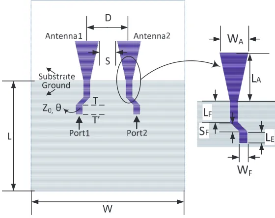
The structure of the two antennas is shown in Figure 2. The center-to-center distance between the two antennas D = 20 mm and the edge-to-edge distance S = 9 mm (about 0.07λ0). Other design
W
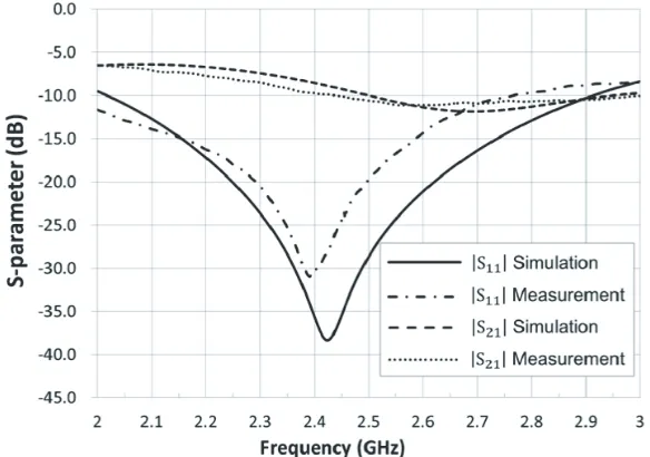
Figure 3. Simulated and measuredS-parameters of the coupled antenna in Figure 2.
Figure 4. Extracted Y-parameters of the coupled antenna in Figure 2 and the mutual admittance of the decoupling network.
dimensions are WA = 11 mm, LA = 20 mm, LF = 7.7 mm, SF = 3.7 mm, LE = 4.5 mm, and WF = 3 mm. The simulated and measuredS-parameters of the MIMO antennas are shown in Figure 3. It is obvious that although the matching bandwidth of each antenna is broad, the isolation between the two elements is poor. The isolation at 2.45 GHz is no more than 8 dB.
To design the decoupling network, the first step is to extract the admittance parameters. In this example, parameter Re{Y21A} is already transformed to zero by a small section of transmission line. After transformation, the admittance parameters of the two coupled antennas are shown in Figure 4. It is obvious that Im{Y21A}=−0.064 at the center frequency. The next step is to design the SRRs such that the mutual admittance of the decoupling network, Im{Y21F}, equals 0.064, which is exactly the opposite of Im{Y21A}. The method is to design the resonant frequency of the resonators and the coupling coefficients MS1, M12, M2L shown in Figure 1. The resonant frequency of the resonator, which is
can be determined using the following expression:
ImY21F≈ −MS1·M2L M12
. (12)
Meanwhile, according to [11], the inter-resonator coupling M12 needs to be as large as the fabrication
process allows, ensuring a relative constant Y21F within the band of interest. In this paper, the value of M12 is constrained by the achievable clearance between two resonators printed on an FR4 substrate,
which is 0.3 mm. Therefore, the obtained M12 equals 2.00 in this example. Since in this design the
coupled antenna network is symmetrical, the decoupling network must also be symmetrical,
MS1=M2L. (13)
Using Equations (9)–(13), the remaining coupling coefficients are determined: MS1 = M2L = 1.09,
M12= 2.00, which can also be obtained by circuit model optimization using Agilent Advanced Design
System (ADS) with the model shown in Figure 1. The final realized Im{Y21F}is also plotted in Figure 4. The physical dimension of the SRRs is shown in Figure 5. The inter-resonator coupling is achieved
1 2 WR
Figure 5. The layout of the decoupling network, the inverters together with the coupled antennas.
-15 -10 -5 0 5
0 30 60
90 120
150
180
210
240
270
300
330
-15
-10
-5
0
5
-10 -5 0 5
0 30 60
90 120
150
180
210
240
270
300
330
-10
-5
0
5
(a)
(b)
by edge coupling, and the input/output coupling is realized by a tapped-line method. The designed parameters are LR = 16 mm, WR = 5 mm, g1 = 0.5 mm, and g2 = 0.3 mm. The feeding position of
tapped-lineF = 1 mm. Notice that two extra quarter-wave transformers (transmission lines of 90 degree electrical length) are added to the network ports to transform the parallel resonator to its series resonator counterpart to ensure the consistence of the physical model with the designed circuit model. It should be noted that other forms of more compact transformers can also be used such as the Pi-equivalent network of lumped elements. Details concerning the resonator design can be found in [15].
4. RESULTS AND DISCUSSION
Three prototypes, including one single antenna, coupled antennas without any decoupling network and decoupling antennas with the SRRs, are fabricated and measured. Their scattering parameters are measured using Keysight E5080A [16], and the radiation characteristics are measured in a SATIMO SG-24 near-field chamber [17]. The envelope correlations of the coupled and decoupled antennas are measured in a Bluetest RTS90 Reverberation chamber [18].
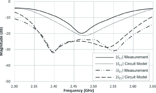
The measured S-parameters of the coupled and decoupled antennas are shown in Figure 3 and Figure 6, respectively. It is seen from Figure 6 that the decoupling bandwidth with |S11| ≤ −6 dB and
|S21| ≤ −20 dB is 9.8%, which shows that a second-order decoupling network can achieve much wider
decoupling bandwidth than the first-order networks such as those in [9] and [13]. It is worth mentioning that a better matching can be easily achieved if a simple matching network is added to each decoupled port.
The radiation power patterns for a single antenna, two tightly coupled antennas, and two decoupled antennas are measured with measured pattern superposed in Figure 7. When measuring the two coupled and decoupled antennas, port 1 is excited, and port 2 is terminated with a matched load. In the coupled antenna case, the terminated load receives the coupled energy, whereas in the decoupled antenna case, the terminated antenna element acts as an ‘invisible’ antenna, and no current is coupled to antenna port 2.
The measured efficiencies are also displayed in Figure 8. The efficiency of the decoupled antennas improves by nearly 10% compared to the coupled antennas. Due to the conduction and dielectric losses introduced by the resonators and two extra quarter wavelength transmission lines, the efficiency of the decoupled array is still smaller than that of the single antenna, but they are very close.
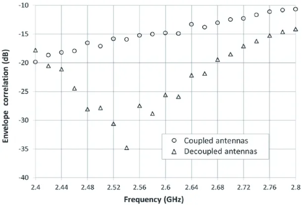
The envelope correlations of the coupled and decoupled arrays are superposed in Figure 9, showing great improvement. It is well known that a lower envelope correlation leads to a better channel capacity.
Figure 9. Envelope correlations of the coupled antennas and the decoupled antennas.
5. CONCLUSION
This paper proposes a general design technique for port decoupling of two tightly coupled antenna elements using SRRs. Decoupling and matching conditions for two tightly coupled antennas are presented. Simulated and experimental results suggest that both port decoupling and matching can be achieved simultaneously over a relative wide bandwidth as compared to other existing decoupling techniques. It has been shown through measured radiation patterns that the decoupled antennas can provide a significant reduction in correlation coefficient, showing a promising application in wireless terminal systems using diversity antennas or MIMO technology. The extension of the proposed technique to dual-band and multi-port decoupling network is under investigation.
ACKNOWLEDGMENT
The authors would like to thank Dr. Kewei Qian, Mr. Li Liu, who are with the Wyzdom Wireless Co., Ltd as well as Mr. Chao Jing, who is with Innowave Co., Ltd for their help in antenna measurement.
REFERENCES
1. Andersen, J. B., “Array gain and capacity for known random channels with multiple element arrays at both ends,” IEEE J. Select. Areas Commun., Vol. 18, 2172–2178, Nov. 2000.
2. Vaughan, R. and J. B. Anderson,Channels, Propagation and Antennas for Mobile Communications, The Institute of Electrical Engineers, London, U.K., 2003.
3. Jensen, M. A. and J. W. Wallace, “A review of antennas and propagation for MIMO wireless communications,”IEEE Trans. Antennas Propag., Vol. 52, No. 11, 2810–2824, Nov. 2004.
4. Yang, F. and Y. R. Samii, “Microstrip antennas integrated with electromagnetic band-gap EBG structures: A low mutual coupling design for array applications,” IEEE Trans. Antennas Propag., Vol. 51, No. 10, 2936–2946, Oct. 2003.
5. Chiu, C. Y., C. H. Cheng, R. D. Murch, and C. R. Rowell, “Reduction of mutual coupling between closely-packed antenna element,” IEEE Trans. Antennas Propag., Vol. 55, No. 6, 1732– 1738, Jun. 2007.
7. Mavridou, M., A.-P. Feresidis, and P. Gardner, “Tunable double-layer EBG structures and application to antenna isolation,”IEEE Trans. Antennas Propag., Vol. 64, No. 1, 70–79, Jan. 2016. 8. Andersen, J. B. and H. H. Rasmussen, “Decoupling and descattering networks for antennas,”IEEE
Trans. Antennas Propag., Vol. 24, 841–846, Nov. 1976.
9. Chang, S., Y.-S. Wang, and S.-J. Chung, “A decoupling technique for increasing the port isolation between strongly coupled antennas,” IEEE Trans. Antennas Propag., Vol. 56, No. 12, 3650–3658, Dec. 2008.
10. Volmer, C., J. Weber, R. Stephan, K. Blau, and M. A. Hein, “An eigen-analysis of compact antenna arrays and its application to port decoupling,” IEEE Trans. Antennas Propag., Vol. 56, No. 2, 360–370, Feb. 2008.
11. Zhao, L., L. K. Yeung, and K.-L. Wu, “A coupled resonator decoupling network for two-element compact antenna arrays in mobile terminals,” IEEE Trans. Antennas Propag., Vol. 62, No. 5, 2767–2776, May 2014.
12. Diallo, A., C. Luxey, P. L. Thuc, R. Staraj, and G. Kossiavas, “Study and reduction of the mutual coupling between two mobile phone PIFAs operating in the DCS1800 and UMTS bands,” IEEE Trans. Antennas Propag., Vol. 54, No. 11, 3063–3073, Nov. 2006.
13. Lau, B. K. and J. B. Andersen, “Simple and efficient decoupling of compact arrays with parasitic scatterers,” IEEE Trans. Antennas Propag., Vol. 60, No. 2, 464–472, Feb. 2012.
14. Pozar, D. M., Microwave Engineering, 3rd edition, Wiley, New York, 2005.
15. Hong, J.-S. and M. J. Lancaster, Microstrip Filters for RF/Microwave Applications, 2nd Edition, Wiley, New York, 2011.
16. [Online], Available: http:// http://www.keysight.com/. 17. [Online], Available: http://www.satimo.com/.